Member postings for Boldminer
Here is a list of all the postings Boldminer has made in our forums. Click on a thread name to jump to the thread.
| Thread: Gloss to Flatt |
| 09/12/2018 09:13:16 |
| Thanks to all that took the time and trouble to reply to my query. I do know of a place here in Phuket where I can buy a matt aerosol so that is the route I'll try first. Regards, the Boldminer |
| 08/12/2018 04:21:45 |
Can anyone tell me if there is a way to alter a gloss finish paint ( supplied wrongly by a UK supplier to me here in Thailand) to produce a Flat finish. The main cause for concern at the moment are the wheels of the loco that have already been painted. Can I simply spray over them with a 'flat' lacquer and would this be OK on the boiler? Your replies would be greatly appreciated.
|
| Thread: no recoil |
| 11/08/2018 13:29:18 |
Michael G, Bazyle , Michael M, John Haine, Dick H and Russell, once again thank you for your support and assistance and again in order of posting :- Michael G that screen shot is a great help and will be used to produce a new anchor. Bazyle thank you for the explanation of the 'proc cess' it has gone a great way to lifting the fog that surrounds the black art. John Haine I really do appreciate you help and advice. To clarify my information about 'the drop' the pallet nib drops approx. 30% down the face of the escape wheel tooth. The face of the teeth were not attacked with a file, merely polished with Crocus paper and still retain their flat tops. Dick H the clock is fitted with an adjustable eccentric, the use of which has been tried (to no avail) , all the arbors do 'rattle' from side to side and the free wheeling action is not impeded by pinching the frames. Russell as I explained to Dick H., there is an eccentric and has been tried, but I must admit that I did not wipe the residual oil from the pallet nibs (will do in future). So gentlemen, after reading your comments I think that the obvious way forward is to produce a new escape pallet with the help of Michael Gs' screen shot and to double check the other relevant dimensions, many thanks , watch this space ! Colin
|
| 10/08/2018 05:00:21 |
Many thanks to Russell, John and Michael, I will try to respond to your posts in order but please bear in mind that I am in no way an horologist or experienced clock maker. RUSSELL, my apologies, the clock is a John Wildings 'large Wheel' clock. The spring thickness does conform to the suggested thickness of .40mm . I have tried the movement with the pallet nibs both wet (not excessive) and dry using 'clock oil' from Meadows and Passmore, all to no avail. JOHN, there is no recoil what-so-ever on the escape wheel. I have tried the clock fully wound but don't get any improvement at all. I have also applied extra torque by increasing the pressure on the large wheel but all that seems to achieves is a louder click as the pallets engage with the escape wheel, incidentally the pallet drop is approx. 30% of the escapement tooth. MICHAEL, you are of course correct, the clock is a John Wildings' Large Wheel clock. Thanks to all, Colin Standish Ps. excellent video ! |
| 09/08/2018 05:50:07 |
I have been trying for two weeks or so now to get this clock to run. All the pivots are polished and free in their respective holes, the train falls from side to side with the 'audible click' the arresting faces of the escape pallet have been brought to a mirror finish as have the corresponding faces of the escape wheel. The spring barrel is free to rotate on its' spindle, the pallet arbor is free and the clock set in beat using an ' amplitic' audio device. When set going there doesn't appear to be any force in the escape wheel that would result in a recoil action sufficient to maintain the momentum of the pendulum. The only thing that I can find at odds with the designed plan is that the spring purchased from Rite-Time for this model does not conform to the spec. quoted by J.W. ie it is aprox. 60thou. down on width. With the escapement disconnected and just one turn on the spring the clock will 'free wheel' for the equivalent of 36hrs. or so, with the escapement engaged ( with several turns on the barrel ) it will not run passed the naturally decayed swing of the pendulum. ANY IDEAS PLEASE ?
|
| Thread: Heritage steam under coal threat |
| 30/05/2013 08:23:44 |
England is floating on several layers of coal including anthracite and 'best steam coal'! It's a fact that most of our present inferior coal supplies are imported from the USSR and other eastern block countries as well as 'some of Mr. Magregors' ( remember him? ) coalmines. It's correct that there are well over 150 years worth of coal left under GB and that just a few mines where ' mothballed ', Assuming that we now have the technology to BURN coal rather than just set fire to it doesn't it make sense to open the mines again. Apparently we are running out of petrol,but, didn't the Germans crack petrol from coal during the war? and this is just one by-product! |
| Thread: Dividing |
| 26/01/2013 13:21:08 |
Thank you very much to everyone that took the trouble to reply to my ' division ' query. After reading through all the replies it became obvious to me that what I have is a simple BSO dividing head with no possibility of compounding. So the information in the 'tables' is correct when you can compound using the rest of the infomation for the particular application. The clock I am making is a 'Large Wheel' skeleton clock by John Wilding but again what I overlooked was the fact that he was using a Myford dividing head with a 60:1 ratio. After following Mr Jones's example using a 99 hole plate I have calculated that the equation results in an error of only .000011 per division which as I used to say is "good enough for the pit". So, now all that remains to be done is to visit a local engineering co. for material for a new plate. So once again thank you Les and the rest of you gentlemen for you time and trouble.
|
| 25/01/2013 15:53:52 |
I wish to index for 198 teeth using a BSO dividing head with a 40:1 worm-wheel. The problem is that the supplied dividing tables give the same results for both 198 and 197 ie. a 20 hole plate at 4/20. This cannot be correct for both, can anyone help please ( 198 ). Do I need to make a special plate ? |
| Thread: exhaust's |
| 17/08/2012 10:35:20 |
thank you Julian, I'm just about to check my actual measurements using auto-cad. |
| 14/08/2012 16:52:11 |
Hello Julian, thank you for your intrest/reply to my query. With regards to the type, size, and spec. of the engine, I hope that the following can be of some help. The engine is a 31/2" K4 to Matin Evans design. The cylinders have a diameter of 1.125" x 1.625" stroke and the boiler barrel is 4.375" dia, barrel length is 8.4" The boiler capacity is approx 2.2ltr and is noted as 12bar litres. The smoke-box as a volume of 56cu.in.( ie. 4.375"dia. x 3.75"long). From the boiler to the top of the chimney the height is .883", the chimney opening is .875"dia. The total length including pettycoat pipe is 2.195" The pettycoat opening is 1.3125" dia and the choke dia. is .75". The choke height is .75" from the bottom of the pettycoat or approx. 1/3 the total height of the chimney regards, Boldminer |
| 14/08/2012 00:16:39 |
Thanks a lot Eddie, that was just the information that I was looking for. Regards, Boldminer |
| 13/08/2012 19:57:33 |
can anyone please advise me of the ratio of blast nozzle dia. to chimney "choke" dia. and the distance between them |
| Thread: fusee stop |
| 07/11/2010 11:55:04 |
Can any-one please explain the operation of the fusee stop in the elegant scroll clock ?.
This is my first venture into clock making and although I have made good progress so far, I am having trouble understanding the fusee stop.
There is no problem in making it, the problem lies with its operation. As I see it the 'iron stop' arrests the rotation of the fusee by contacting the stop plate attached to the end of it. However the drawing of the component parts shows the bottom edge of the fusee iron to be ' square ' to the bottom of the fusee block to which it is fitted via the locating pin. If this is the case then the ' iron ' is locked into the ' block ' with no rotation afforded to it.
In this situation I would assume that once it as made contact, the fusee will be stopped from moving any further...... however, also mentioned is a return spring that keeps the' iron ' out of the way of the fusee cap. So, am I to assume that the bottom of the ' iron ' should have a 1/4" radius on it, or at least on one side of it to allow movement ?.Lastly is it the action of the the wire pushing on the large radiussed side of the ' iron ' which causes it to be pushed out of the way of the fusee cap ?.
I think that the answers are obviouse but they are only obviouse to those that know and in this instance I would like to know also. Many thanks.
|
| Thread: Collet Chuck |
| 21/10/2010 14:20:00 |
|
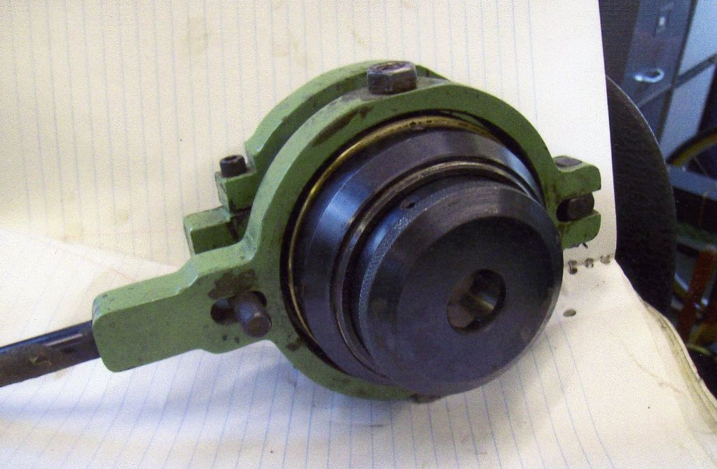
Is the any-one out there who can inform me of the type/name of the collets which should be used with the 'Warco' chuck illustrated and where they can be purchased ? The collet drawing shows approx. sizes of a style that should fit. The chuck was purchased some 10 years ago but as of yet Warco have still not been able to provide me any usable collets. They did recently supply 2 sample collets for me to try but unfortunately neither were suitable. Warco's finnal advice was, "look on the internet, I'm sure you will find some out there somewhere" . I was not really impressed but here goes, HELP! |
| Thread: Indexing |
| 22/06/2010 16:57:52 |
Thanks to every-one that took the trouble to reply to my query. In the end I realised that 96 divisions where not possible using the BS0 and the plates supplied. A trip to a local engineering who gave me a 6 x 100mm. dia blank. This enabled me to make a new 24 hole wheel. I know a 12 would do the job as well but whilst I was drilling for 12 I might as well drill for 24 ( looks a bit better I think ). Anyhow problems solved and the jobs done, thanks again folks.
|
| 19/06/2010 13:16:35 |
Can any-one out there explain the meanings of the 'A,B,C,D,E and F' rows in the divding tables at the back of operating instructions manual for the Vertex BS0 model dividing head. Also what do the numbers in these rows refer to? |
| Thread: Tom Senior M1 Mill Arbour thread |
| 15/06/2010 12:03:51 |
Hi Graham, just read your post re: drawbar thread. I have a Tom Senior M1 ( No.3190) and I have just been to check it for you. My drawbar is 16.375" long, as a nominal shank dia. of .5" (.498"measured) and a thread length of 1.625". The thread measured .490"od and the 'Whit' thread gauge of 12 tpi. fit perfectly. I would therefore assume that this is just a loose fitting 1/2"Whit form. It as always been an easy fit in the arbour, down to the last thread. Hope the info can be of use. |
| Thread: wheel cutters/cutting |
| 03/06/2010 20:09:23 |
thanks for the reply Jason, as I said in the posting the information in John Wildings consrtuction manual states : Great Wheel 96 teeth - 43DP P.C.D. 2.8" O.D 2.9" but I have been supplied with module cutters instead of DP. |
| 03/06/2010 19:28:02 |
I have just cut the teeth on the great wheel of the above mentioned clock, ie. 96 teeth. This is my first attempt at clock-making and some how the end result dosn't look right!......I sent for the rerquired 34 & 42 D.P. cutters from a well known supplier who quickly responded but sent me a 0.75 and a 0.6 module cutter. When questioned, I was told that the 0.75-W cutter was to be used instead of the 34DP and the 0.6--W instead of the 42DP and everything will turn out OK. I also asked about the depth of cut as it was not indicated on the cutter as I had expected and was told to cautiously increase the depth of cut on 2 adjacent teeth until the radii on the top blend to make one continuous arc. I did this but to me the 'space' appears to be significantly larger than the tooth.....
I have studied the information and reference books which I have but all I have succeeded in is confusion! Apart from returning the cutters and starting again is there any-one out there who can help resolve my problem/confusion?
NB. the cutter blank was was exactly to size as required ie. 2.9" OD and the teeth cut until the radii just met. |
| Thread: Auto Cad |
| 17/11/2009 16:15:20 |
Is there anyone out there that can me how to create a Dxf. file for an auto-cad drawing. Am I right in what I am asking for? I believe this is what is required if you would like something to be produced by water-jet cutting etc.. When created is this file simply downloaded to a disc that is sent to who ever is undertaking the work? Does the drawing/file have to include all of the dimensions ? |
Magazine Locator
Want the latest issue of Model Engineer or Model Engineers' Workshop? Use our magazine locator links to find your nearest stockist!
Sign up to our Newsletter
Sign up to our newsletter and get a free digital issue.
You can unsubscribe at anytime. View our privacy policy at www.mortons.co.uk/privacy
Latest Forum Posts
- hemingway ball turner
04/07/2025 14:40:26 - *Oct 2023: FORUM MIGRATION TIMELINE*
05/10/2023 07:57:11 - Making ER11 collet chuck
05/10/2023 07:56:24 - What did you do today? 2023
05/10/2023 07:25:01 - Orrery
05/10/2023 06:00:41 - Wera hand-tools
05/10/2023 05:47:07 - New member
05/10/2023 04:40:11 - Problems with external pot on at1 vfd
05/10/2023 00:06:32 - Drain plug
04/10/2023 23:36:17 - digi phase converter for 10 machines.....
04/10/2023 23:13:48 - More Latest Posts...
- View All Topics
Support Our Partners


Shopping Partners
Subscription Offer

Latest "For Sale" Ads
- Reeves** - Rebuilt Royal Scot by Martin Evans
by John Broughton
£300.00 - BRITANNIA 5" GAUGE James Perrier
by Jon Seabright 1
£2,500.00 - Drill Grinder - for restoration
by Nigel Graham 2
£0.00 - WARCO WM18 MILLING MACHINE
by Alex Chudley
£1,200.00 - MYFORD SUPER 7 LATHE
by Alex Chudley
£2,000.00 - More "For Sale" Ads...
Latest "Wanted" Ads
- D1-3 backplate
by Michael Horley
Price Not Specified - fixed steady for a Colchester bantam mark1 800
by George Jervis
Price Not Specified - lbsc pansy
by JACK SIDEBOTHAM
Price Not Specified - Pratt Burnerd multifit chuck key.
by Tim Riome
Price Not Specified - BANDSAW BLADE WELDER
by HUGH
Price Not Specified - More "Wanted" Ads...
Get In Touch!
Do you want to contact the Model Engineer and Model Engineers' Workshop team?
You can contact us by phone, mail or email about the magazines including becoming a contributor, submitting reader's letters or making queries about articles. You can also get in touch about this website, advertising or other general issues.
Click THIS LINK for full contact details.
For subscription issues please see THIS LINK.
Digital Back Issues


Donate

 Register
 Log-in
Model Engineer Magazine
- Percival Marshall
- M.E. History
- LittleLEC
- M.E. Clock

ME Workshop
- An Adcock
- & Shipley
- Horizontal
- Mill

Subscribe Now
- Great savings
- Delivered to your door

Pre-order your copy!
- Delivered to your doorstep!
- Free UK delivery!