Member postings for Dr_GMJN
Here is a list of all the postings Dr_GMJN has made in our forums. Click on a thread name to jump to the thread.
| Thread: Stuart Twin Victoria (Princess Royal) Mill Engine |
| 29/08/2022 10:01:13 |
I need to sort out the turning before I can progress. Do you think a left-had turning tool would be ok - no radius and the flats would be easier to grind? A bit like the boring tool geometry on the round off-cuts Ramon sent me. They seemed fairly easy to get right, although it was on cast iron. Thanks. |
| 28/08/2022 21:12:05 |
This is the centre drill I’ve got: The centering bar I made is spring loaded - works fine. Yes, I hold the end from rotating during measurements. Thanks. |
| 28/08/2022 17:13:26 |
Thanks Jason. I’ll re-draw for 1/2” and treat it as a machining trial. Im not really sure what you mean by ‘honing’. I’ve got a large ‘oil stone’ for chisels, and some ARC diamond laps, but it seems like whenever I try to clean up a cutting edge, I actually get the angle slightly wrong and end up - probably - dulling the edge. I find it difficult to judge whether the abrasives are actually doing anything, often feels like they’re just skimming across the surface without touching it. The only way I can do it is by trial and error - usually error, and…it just brings me one step closer to packing up the tools and doing something else, when I really want to make progress. |
| 28/08/2022 16:30:50 |
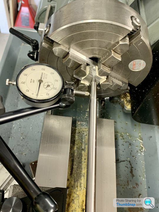
Hmmm bit of a rubbish day on this, with little to show for a lot of effort. Same old story when turning steel - poor surface finish, plus it’s inconsistent. Also, for the lengths and step sizes I need, my HSS tool is too big and clunky - undercut lengths are huge. It didn’t give a very good finish on the actual shaft material either: Also realised my drawing is no good, since stepping the shaft has given me a middle section bigger than the stock 1/2” material I got. I could use the 7/16” stock, but as discussed before, it’s slightly undersized, and gives 0.002” runout after centering. It looks pretty thin before skimming it to give no runout. The step sizes also become very small. I’ll probably re-draw it for the 1/2” stuff, but ending at 12.5mm or something. |
| 28/08/2022 09:49:31 |
Thanks Jason, yes that what I meant. I’m not sure what you mean by back end wants to be free though? |
| 28/08/2022 00:27:06 |
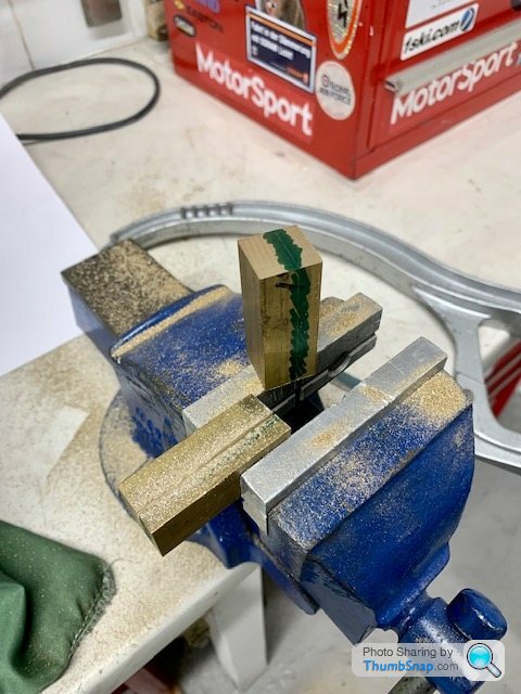
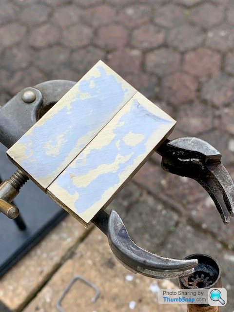
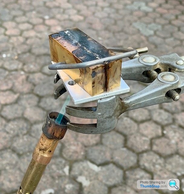
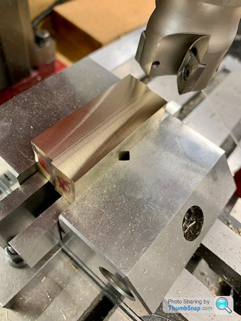
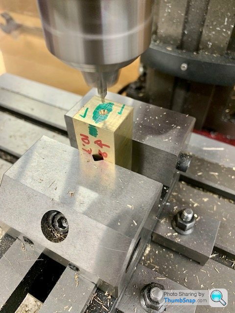
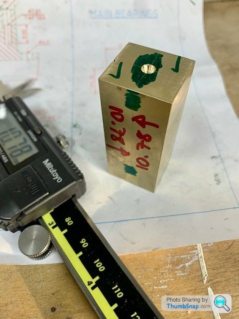
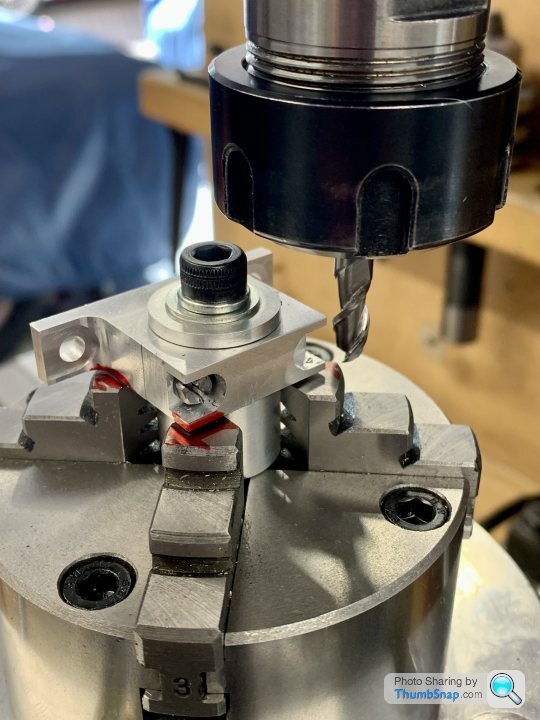
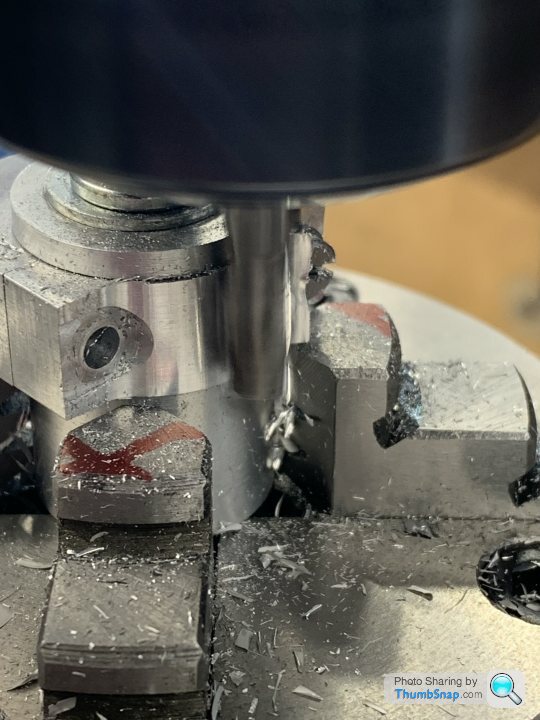
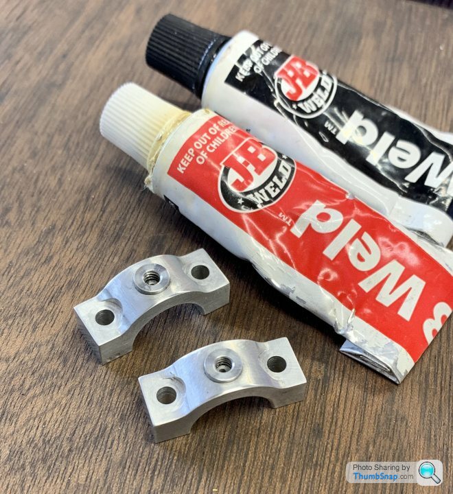
Didn't have much workshop time today, so prepared material for the split main bearings.
One question regarding this: I assume that if this single bar is for both bearings, then I bore all the way through (in order to be able to get the journal lengths fully engaged beyond the crank spigot), periodically checking fit on the shaft? Once parted-off for the first bearing, I'd double-check for fit on the other journal? I assume that the bore will taper slightly, so, assuming both journals are identical diameter, the second bore might need a spring pass or perhaps a few? |
| 26/08/2022 10:00:42 |
Re-worked the shaft drawing slightly, to revise the step lengths to give about 0.25mm float for bearing adjustment. I've also removed the undercut from the first steps adjacent to the eccentrics, since they're no longer needed (nothing abutts them). *ETA I guess I could also eliminate the undercuts at the inner ends of the bearing steps, since they no longer abutt the bearing faces. Would just need a decent chamfer or radius on the inside of the bearing bore? Edited By Dr_GMJN on 26/08/2022 10:02:24 |
| 25/08/2022 16:52:23 |
Yes, bosses on both sides of the eccentric with blend radii to the disc. Drawing just represents the overall width of the part to get the shaft dimensions about right. |
| 25/08/2022 16:19:13 |
Understood about the need for a bit of end float on the bearings. I've modified the cylindrical lengths to give about 0.25mm float, which can be adjusted to zero by snugging the eccentric against the bearing face, the eccentric subsequently being secured with grub screws (the fitting of which has been previously covered by one of Ramon's posts): |
| 25/08/2022 07:38:01 |
Thanks all. What about using an HSS parting tool, ground with a radius, then do the undercuts to final depth (after roughing to the largest o/d? Then work on the diameters knowing that the tool will run into the groove and the lengths are already correct? Ramon - I made a saddle stop a while ago, but probably don’t use it as much as I should. My saddle hand wheel is a bit sloppy, and if using power feed it’s easy to strain the drive when it hits the stop if I do t release the feed at precisely the right time. Jason - so for the long central length, how do you get an accurate length? Not sure my top slide has the range (will have to check). Do you check for top slide x-alignment with a dti? Mine can turn and just had an angle scale on it with two clamp bolts. So potentially all the careful setup of the tailstock to turn parallel could be negated by using the top slide unless it’s set perfectly parallel. Edited By Dr_GMJN on 25/08/2022 07:38:45 |
| 24/08/2022 22:22:13 |
So regarding the crankshaft. Following Ramon's advice, I had a go at grinding an HSS tool. It's not pretty: |
| Thread: Glass Drip-oiler Design / Manufacture Advice |
| 24/08/2022 11:17:38 |
Thanks both. Andy - the sight glass on mine would purely be a visual feature - it would immediately get full of oil, but I’m not too concerned about that so long as oil gets to the bearings. The wick idea might be good for the big ends, but I guess the plain Stuart type with a cap would suffice (without an actual wick)? |
| 24/08/2022 09:44:31 |
Thanks all, very helpful. I'll stick with the parallel tube, and the spigot location method because it gives a good shear area for the Araldite to grip. I tried Araldite last night, and this morning the assembly is rock solid. I'll turn down the centre portion of the 'glass' slightly and polish it back clear, to give the impression of lipped caps (the O/D is currently a bit oval anyway, plus the wall thickness is a bit thick, so all good). I'll reduce the glass length to 6mm, flatten the upper cap a bit, and add fill and vent holes. I'll also re-design the necked part at the bottom slightly, cross-drill it, push a tight fitting drill smeared with vaseline down the oil hole, and fill the cross-holes with optically clear Araldite to form the sight glasses. What is the best way to form the knurled adjuster tops? Do I need a special knurling tool? I've got a crosshatch tool, but it's a bit dodgy. Thanks all.
|
| 23/08/2022 21:32:57 |
All, I'm building a Princess Royal mill engine: |
| Thread: Stuart Twin Victoria (Princess Royal) Mill Engine |
| 21/08/2022 19:31:56 |
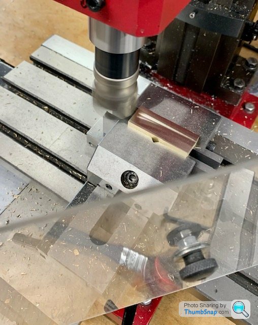
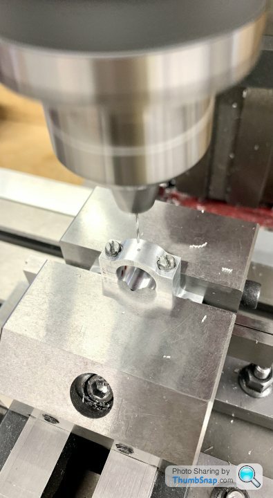
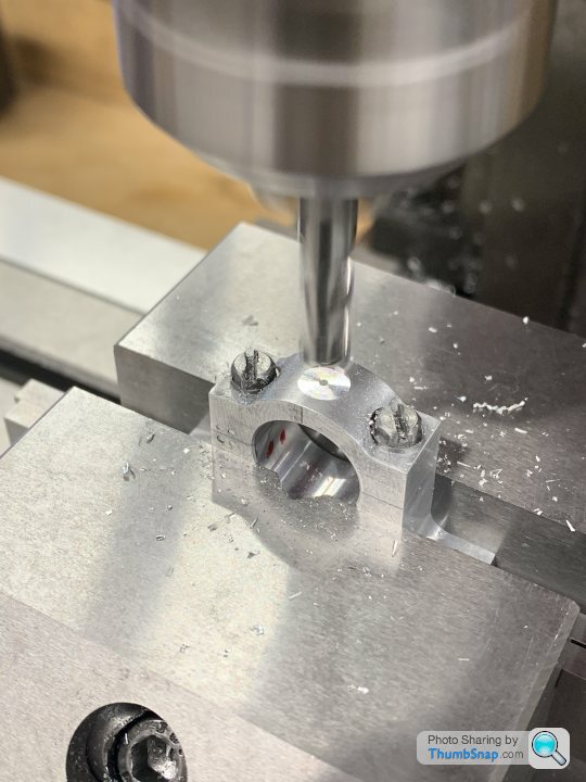
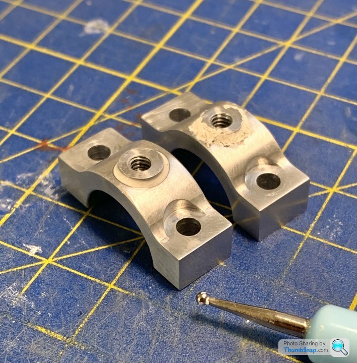
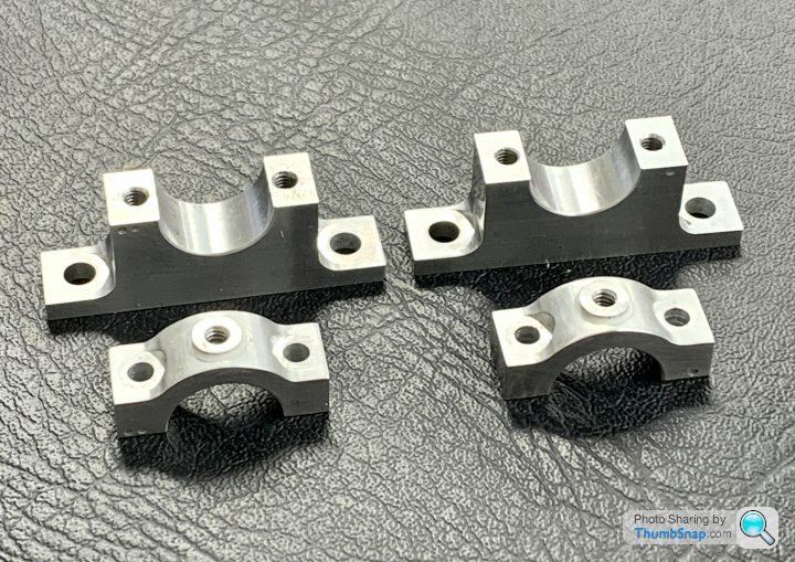
Continued with the housings, a repeat of the previous process with a few minor tweaks for the additional radii: |
| Thread: Stuart 10V Build Log - Complete Beginner... |
| 20/08/2022 10:32:22 |
I found my old Museum guidebook, it doesn’t give much more info. The builder is Karl-Friedrich Pohlmann. he also built a model of the Titanic’s engines, but must admit I didn’t notice them in the museum last week: I can’t find out anything about the builder online. Certainly seems to know what he’s doing though!
|
| 18/08/2022 09:31:00 |
Yes I’ve seen the washer stack thing on other marine engines. I expect the axial forces when going from full ahead to full astern are pretty monumental. |
| 18/08/2022 08:15:18 |
Some more general info here: |
| 18/08/2022 08:14:57 |
Posted by Martin Connelly on 18/08/2022 07:52:01:
As a child I remember seeing lots of scale models of ships and their engine rooms in Liverpool museums. They were used to both get money for the shipyards to go ahead with the full size build and also to make sure everything fitted together when built. It was also a way for craftsmen to see what was to be made without having to interpret hand drawn paper plans at every stage. Modern CAD has made a lot, if not all, of this preparatory work obsolete. Martin C Yes, a lot of the models at the museum were made by or for shipyards or shipping lines. IIRC Basset Lowke used to build a lot of one-off models like this? |
| 18/08/2022 07:25:58 |
Posted by noel shelley on 17/08/2022 21:36:12:
My limited german seems to indicate that the description of the" Deutschland" engines states that it had Quad expansion engines! Noel. That’s how I understand it. Not much online about the engines, but the German Wikipedia seems to say they were 6 cylinder engines. The UK Wikipedia doesn’t mention them. Is the additional small cylinder above the 10V the main cylinder, and the lower one a compound? |


Magazine Locator
Want the latest issue of Model Engineer or Model Engineers' Workshop? Use our magazine locator links to find your nearest stockist!
Sign up to our Newsletter
Sign up to our newsletter and get a free digital issue.
You can unsubscribe at anytime. View our privacy policy at www.mortons.co.uk/privacy
Latest Forum Posts
- hemingway ball turner
04/07/2025 14:40:26 - *Oct 2023: FORUM MIGRATION TIMELINE*
05/10/2023 07:57:11 - Making ER11 collet chuck
05/10/2023 07:56:24 - What did you do today? 2023
05/10/2023 07:25:01 - Orrery
05/10/2023 06:00:41 - Wera hand-tools
05/10/2023 05:47:07 - New member
05/10/2023 04:40:11 - Problems with external pot on at1 vfd
05/10/2023 00:06:32 - Drain plug
04/10/2023 23:36:17 - digi phase converter for 10 machines.....
04/10/2023 23:13:48 - More Latest Posts...
- View All Topics
Support Our Partners


Shopping Partners
Subscription Offer

Latest "For Sale" Ads
- Reeves** - Rebuilt Royal Scot by Martin Evans
by John Broughton
£300.00 - BRITANNIA 5" GAUGE James Perrier
by Jon Seabright 1
£2,500.00 - Drill Grinder - for restoration
by Nigel Graham 2
£0.00 - WARCO WM18 MILLING MACHINE
by Alex Chudley
£1,200.00 - MYFORD SUPER 7 LATHE
by Alex Chudley
£2,000.00 - More "For Sale" Ads...
Latest "Wanted" Ads
- D1-3 backplate
by Michael Horley
Price Not Specified - fixed steady for a Colchester bantam mark1 800
by George Jervis
Price Not Specified - lbsc pansy
by JACK SIDEBOTHAM
Price Not Specified - Pratt Burnerd multifit chuck key.
by Tim Riome
Price Not Specified - BANDSAW BLADE WELDER
by HUGH
Price Not Specified - More "Wanted" Ads...
Get In Touch!
Do you want to contact the Model Engineer and Model Engineers' Workshop team?
You can contact us by phone, mail or email about the magazines including becoming a contributor, submitting reader's letters or making queries about articles. You can also get in touch about this website, advertising or other general issues.
Click THIS LINK for full contact details.
For subscription issues please see THIS LINK.
Digital Back Issues


Donate

 Register
 Log-in
Model Engineer Magazine
- Percival Marshall
- M.E. History
- LittleLEC
- M.E. Clock

ME Workshop
- An Adcock
- & Shipley
- Horizontal
- Mill

Subscribe Now
- Great savings
- Delivered to your door

Pre-order your copy!
- Delivered to your doorstep!
- Free UK delivery!