Member postings for Rainbows
Here is a list of all the postings Rainbows has made in our forums. Click on a thread name to jump to the thread.
| Thread: A New Way to Injure Yourself |
| 28/11/2017 21:13:11 |
I did a similar thing but I used a scalpel rather than a screwdriver for my print fettling. Should of bought the sterile blade option |
| Thread: Lathe, Vertical mill, Horizontal mill & Shaper |
| 26/11/2017 01:23:33 |
A master craftsment can use all 4 tools on there are the same time on the same workpiece |
| Thread: 3D printed mini lathe compound leadscrew bearing |
| 22/11/2017 02:41:36 |
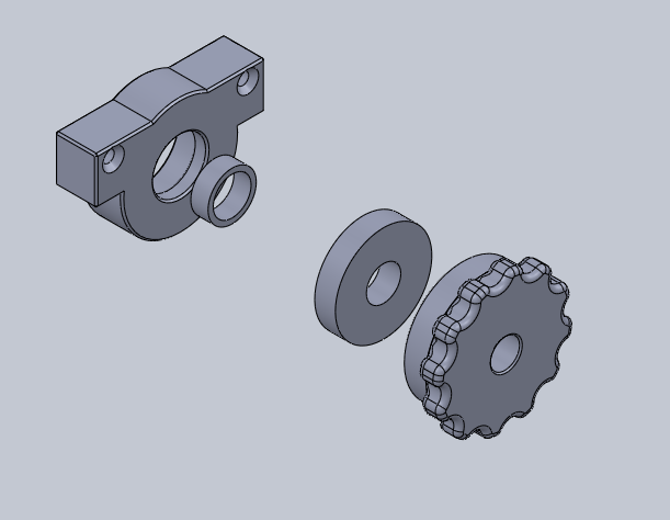
This has certainly been done before, but probably not with a 3D printer. Didn't like the original housing for the compound slide leadscrew on my minilathe. Had some wiggle in it as it came and adjusting the two nuts were a pain and having to find an allen key to change the dial is just criminal. But also to make the new parts I would need a lathe, and to test fit them I would need to take the lathe I was using apart. Also I wanted an excuse to play with my 3D printer
Basic bearing housing to press a 6900 bearing into. The ring makes sure the dial bears not on the housing but onto the inner race of the bearing. Then the ring is a simplified model of a thrust bearing so that the dial doesn't move while the nut is being tightened. Then there is the hand nut which gets tapped for M10 to fit on the existing thread.
Total cost was £7 in bearings and some plastic and 3 hours of printing including fudge ups. Except for 2 tapped holes in the upper compound no changes were made to existing lathe parts. Also have 9 6900 bearings leftover now to boot. Plan to replace all the parts with steel in the fullness of time, but for now it works much nicer than the original. Edited By Neil Wyatt on 22/11/2017 08:50:38 |
| Thread: Some tool ID |
| 18/11/2017 19:24:38 |
Bought a box of lathe tools on the logic of buying the knurling tool and it just happened to come with a bunch of bits I didn't need.
First thing is these guys. The top rotates freely and slides axially a bit. There are two cylinders in each part that will stop the rotation when it reaches one limit and there is a tenon in the shank that will stop rotation when it reaches the other limit. Originally I thought maybe some sort of tapping fixture but I can't see any way to hold the tap in place.
The front part of this can rotate, move back and forth and wobble. Theres a knurled ring mid way that can reduce the play of the front part. The bore in the front piece doesn't appear to have any way of holding something inside.
Clearly a tiny lantern tool post but not sure from what lathe
I feel like these are used to offset capstan tools so they can work on larger parts but not really sure either. Anyone know what these are or what machine they came from? Also came with a bunch of capstan tooling so I have a feeling its to do with a capstan machine but not sure.
|
| Thread: What to do with a old bench lathe (relmac) |
| 11/11/2017 14:45:17 |
Some people are born with lathes and some have lathes thrust upon them I now have a Relmac of average conditions with what appears to be all parts and a 10 year old layer of grease and dust along with its makers cast iron stand. I have my Keighley for big stuff and CJ18A for small stuff. The Relmac sits there as a more worn out, obsolete version of the CJ18A. Apart from sticking it on ebay, the easy and sensible option, are there any alternate uses for a small lathe? Some other machine to use it as a base for?
|
| Thread: How to convert 440V only motors to 240V: a tutorial |
| 09/11/2017 10:20:51 |
I don't know if this is just me but I appear to have magically unlocked the new forum layout where everything is very tall and thin |
| 09/11/2017 10:19:51 |
Oh look the motor is back together, might of missed a bit there. Just don’t let the wires get in the way of the studs holding the motor plates together and don’t let anything get caught when it comes together. Here all 6 wires have been brought out into the open air. Ian is testing for continuity with the probes in his hands, and is matching the U1+U2, V1+V2 and W1+W2 wires into pairs. You can see two pairs have been found and ziptied together. Testing the third pair is kind of a unnecessary step but it double checks everything works.
Here is the delta formation being wired up. The old wire from one pair is spliced with the new wire from the next pair. The old wire from the 2nd pair is spliced with the new wire from 3rd pair. The old wire from the 3rd pair is then spliced onto the last new wire on the original pair.
The newly joined wires are stuck into a terminal block and connected to an inverter to check they work.
Originally we had this on a video but we missed out the entire motor reassembly and I think I remember Ian wanting the audio stripped off and replaced with captions and video editing is a lengthy process. Video might come out in the next holiday when I have more time in life. |
| 09/11/2017 10:18:26 |
Well I wrote all this up like 2 weeks ago then the forum ate it when I pressed create thread so I went off in a huff and procrastinated for 2 weeks before writing it up in word. Lets see how messed up it gets as I transfer from word to the forum. Also big thanks to Ian for fixing my motor up and showing me how to do this.
Here is a wiring diagram pulled off the internet showing the different ways to wire a motor terminal. The star connection works on 415V and the delta connection works in 240V. On these diagrams there are 6 terminals on the wiring diagram.
My motor instead had 3 wires poking out the motor itself which were then screwed into the terminal block. This gives us U1, V1 and W1.
Here the end of the motor has been taken off showing our U1, V1 and W1. Ian is snipping off the cord that ties the wires in place for better access. We have no U2, V2 or W2 though. In our motor diagram above U2, V2 and W2 have been bridged at the terminal but in our actual motor all 3 wires have just been soldered together inside the casing. You need to find the other 3 wires and track down where they are all joined. In my motor the wires were well hidden so we found what looked to be a joint on one wire and tore it apart hoping for the best.
Here is the raw image, you can't really tell what’s going on so here is a professional altered image for clarity.
U1, V1 and W1 are just hanging out the motor, we don't care about them. We found the U2 cable and yanked on it, showing us the location of the "star point" where all the "2" wires meet. U2 is sitting off on the right while W2 and V2 and still entwined, both disappearing into the motor housing. You could at this point take out a multi tester and check that none of the wires are broken. If you haven't got 3 pairs of unbroken wire, then I think your motor is toast. The wires are pretty short right now, not designed to pass out the casing, so we solder an extension onto each wire. Gently sand the end of each wire to get rid of the enamel then solder on an extra length of wire.
Here is some heat shrink being fitted over the soldered joints. Look at that nice fresh blue wire. |
| 06/11/2017 20:30:02 |
Speaking of pairs feel free to make two vertical heads and send me one |
| Thread: stick out |
| 04/11/2017 12:32:09 |
What is the capacity for your 4 jaw? To copy a mini lathe headstock that has a MT3 socket and 35mm shaft. If you use a 32007X bearing with an OD of 62mm you could use 70mm stock and have a decent 4mm wall to your bearing housing. |
| Thread: Spurious Accuracy |
| 03/11/2017 21:59:00 |
Posted by Tony Pratt 1 on 03/11/2017 18:31:52:
Posted by Rainbows on 03/11/2017 17:49:07:
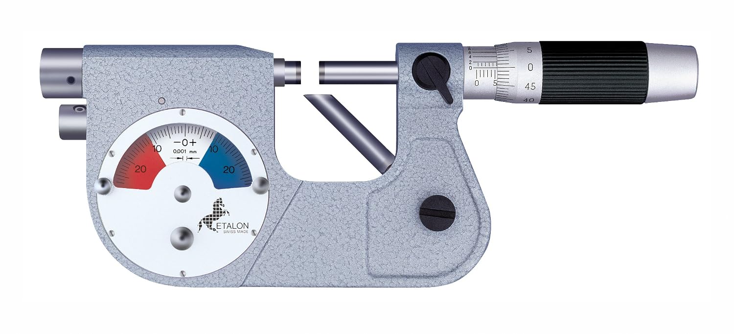
I recently purchased an Etalon micrometer that measures in 0.00005" or 0.00127mm as part of a job lot. Anyone got some bacteria cultures they want measuring?
How does it achieve that? Measuring in .0001" is problematic at the best of times [from a Toolmaker who walked the walk not talked the talk] Tony
Here is my understanding of it, as you can see its not a standard micrometer to begin with. Say you want something 0.5" in diameter. First you set the micrometer barrel to 0.5" then you slide in a gauge block or other standard of 0.5" inbetween the anvils (one is sprung). The lower dial on the clock face lets you callibrate the dial so you would set it to read 0. After that you put your work piece in and it will show how under or oversize it is compared to the standard. This would all be done with it in a micrometer stand, don't want to warm it up at all. |
| 03/11/2017 17:49:07 |
I recently purchased an Etalon micrometer that measures in 0.00005" or 0.00127mm as part of a job lot. Anyone got some bacteria cultures they want measuring? |
| Thread: Always check how big your purchase is |
| 01/11/2017 21:05:58 |
Its going to turn out to be useful... Im just not sure when... Or how... (suggestions welcome) Originally I thought I had a 4HP flexible shaft grinder so would have been a pallet anyway, then it turned out to have glitched the system and I was never told I was outbid :'( I needed a pallet anyway though so oh well |
| 01/11/2017 14:32:08 |
A short cautionary tale on checking how big things are before you buy them I was buying a bunch of stuff at an online auction and at the last second noticed an angle plate, it had no size or weight in the description but I decided to buy it anyway since it was going cheap. My thoughts were to mount if on the Centec table for when I want to use the horizontal spindle like a vertical one. Heres what I got in the post compared with the Centec
Welded from 30mm plate with 400x300mm faces, almost weighs as much as the Centec
|
| Thread: Refitting a 400V only motor to 230V |
| 26/10/2017 01:03:12 |
Ooh thank you very much for the offer, will message you tomorrow and find out when is a good time to bring the motor about. |
| 25/10/2017 18:10:37 |
I keep accumulating motors where its 400V 3 ph only. Having recently seen some 400V motors hacked to be in delta/230V when the original wiring was only for star I wanted to convert mine. Google keeps finding things about rewiring motors that already works on 230 and 400v though. Anyone got a link to a good tutorial on rewiring the motor windings? |
| Thread: Weird triple flute drills |
| 20/10/2017 20:35:33 |
Posted by Ian Parkin on 20/10/2017 16:21:21:
I’ll have some of your mt 3 drills rainbows? What sort of price you looking at? I’m in sheffield S7 where are you? Ian Im at S2, near the football stadium. Im thinking of £4 for the good drills, £3 for the drills that need a slight touch up and £2 for the ones where it needs a fair regrind. Got 6 of the first, 2 of the middle and 2 of the last. Mostly Dormer with a Cleveland and a Guhring with it. Could send an exact list of the sizes if you are interested? |
| 20/10/2017 16:16:40 |
Got a big ole bunch o big drills. Going to move the MT3 ones on since my machines are MT2. Found two odd ones in the batch though. Anyone know what they might be for? 1 5/32" dormer
63/64" dormer
|
| Thread: New 3d printer |
| 17/10/2017 18:58:50 |
Using Wanhao Maker, the documentation is uhh pretty scarce. Will have to have a click about to find retraction. |
| 17/10/2017 15:49:27 |
My first printer was a cheap chinese rerap thingy with MDF, was dead on arrival. Worse investment than a super adept. My new (to me) Wanhao 5S arrived a few days ago, just got the chance to use it last night.
Didn't think it was too bad for right out the box on the coarse setting. There are quite a few stringy bits poking horizontally where the extruder has had to go between different parts of the print over a gap. Is this a thing I just have to deal with or is there a way to tune it out? It won't be much effort to debur with a scalpel I think but was wanted to check if its an issue in the printer.
Edited By Neil Wyatt on 17/10/2017 17:39:32 |


Magazine Locator
Want the latest issue of Model Engineer or Model Engineers' Workshop? Use our magazine locator links to find your nearest stockist!
Sign up to our Newsletter
Sign up to our newsletter and get a free digital issue.
You can unsubscribe at anytime. View our privacy policy at www.mortons.co.uk/privacy
Latest Forum Posts
- *Oct 2023: FORUM MIGRATION TIMELINE*
05/10/2023 07:57:11 - Making ER11 collet chuck
05/10/2023 07:56:24 - What did you do today? 2023
05/10/2023 07:25:01 - Orrery
05/10/2023 06:00:41 - Wera hand-tools
05/10/2023 05:47:07 - New member
05/10/2023 04:40:11 - Problems with external pot on at1 vfd
05/10/2023 00:06:32 - Drain plug
04/10/2023 23:36:17 - digi phase converter for 10 machines.....
04/10/2023 23:13:48 - Winter Storage Of Locomotives
04/10/2023 21:02:11 - More Latest Posts...
- View All Topics
Support Our Partners


Shopping Partners
Subscription Offer

Latest "For Sale" Ads
- Reeves** - Rebuilt Royal Scot by Martin Evans
by John Broughton
£300.00 - BRITANNIA 5" GAUGE James Perrier
by Jon Seabright 1
£2,500.00 - Drill Grinder - for restoration
by Nigel Graham 2
£0.00 - WARCO WM18 MILLING MACHINE
by Alex Chudley
£1,200.00 - MYFORD SUPER 7 LATHE
by Alex Chudley
£2,000.00 - More "For Sale" Ads...
Latest "Wanted" Ads
- D1-3 backplate
by Michael Horley
Price Not Specified - fixed steady for a Colchester bantam mark1 800
by George Jervis
Price Not Specified - lbsc pansy
by JACK SIDEBOTHAM
Price Not Specified - Pratt Burnerd multifit chuck key.
by Tim Riome
Price Not Specified - BANDSAW BLADE WELDER
by HUGH
Price Not Specified - More "Wanted" Ads...
Get In Touch!
Do you want to contact the Model Engineer and Model Engineers' Workshop team?
You can contact us by phone, mail or email about the magazines including becoming a contributor, submitting reader's letters or making queries about articles. You can also get in touch about this website, advertising or other general issues.
Click THIS LINK for full contact details.
For subscription issues please see THIS LINK.
Digital Back Issues


Donate

 Register
 Log-in
Model Engineer Magazine
- Percival Marshall
- M.E. History
- LittleLEC
- M.E. Clock

ME Workshop
- An Adcock
- & Shipley
- Horizontal
- Mill

Subscribe Now
- Great savings
- Delivered to your door

Pre-order your copy!
- Delivered to your doorstep!
- Free UK delivery!