Member postings for John Baron
Here is a list of all the postings John Baron has made in our forums. Click on a thread name to jump to the thread.
| Thread: How do I remove this small bearing? And the one behind it. |
| 09/04/2021 10:57:50 |
Hi Guys, It won't be the first time that I have made a mandrel to remove bearings in blind bores. First most bearings that I've come across tend to have a slight chamfer on the edges. So I've turned suitable piece of rod to be a good fit in the bore, drilled down the centre and split the end with a hacksaw, then clamped the split in a vise and threaded it. Using a suitable bolt threaded into it the split is forced apart and will grip the bearing bore very securely. You can then use any convenient method to remove the bearing such as a hooked slide hammer.
|
| Thread: LG TV ... updated webOS |
| 09/04/2021 10:36:08 |
Posted by Michael Gilligan on 08/04/2021 20:10:12:
Interesting post by a Privacy Lawyer : **LINK** https://www.lexology.com/library/detail.aspx?g=bf6d90ba-5fac-47e4-80b5-d961efac6362 MichaelG. . P.S. __ It’s not just LG Hi Michael, Guys, While the information given in that link is OK, the website itself loads a bucket load of code into your browser ! Which actually does all the things that were are trying to prevent. It mainly uses "Java & Javascript" to basically hack the web browser. Something you definitely don't want on a Wins machine !
|
| Thread: Home Made Rear Toolpost Issue |
| 06/04/2021 09:01:04 |
Posted by Dr_GMJN on 05/04/2021 23:32:05:
This is a top view of the lathe showing the front toolpost, and rear post. The front post is usually angled a bit, and the tool not extended as much, which makes the relative clearances shown fairly representative. You can see that there is not much room with the rear post in place, and it’s far less risky and stressful to simply remove it: Hi Dr GMJN, I agree with your comment about completely removing the rear TP when not needed. I don't remove mine, but then I have the extended cross slide. However looking at your second picture and putting a rule across between the two tools, there is a definite height difference between them ! I assume that you are going to make a tool height setting gauge. If so you will be able to instantly see which is right. While I think about it, the height given it the drawing that I posted needs to be adjusted to suit your centre height. I did mention how I did it on mine. I really don't understand why it should be so difficult to get and set the tool height. I made and use the "Norman Patent" tool posts on both front and back of my cross slide ! No shims needed and always dead on height. Actually I think that making one is a very good turning and boring exercise.
|
| 05/04/2021 17:24:07 |
Posted by Dr_GMJN on 05/04/2021 11:07:35: Ok thanks guys. So I could make a gauge similar to Johns. To get the height, perhaps put some bar in the chuck, then measure the height by putting slip gauges on the cross slide, then add the radius of the bar? Then machine to that dimension? I don’t have a height gauge, but have got most of a set of second hand slips. Hi Guys, The easy way to get your lathe centre height is to put a scriber in the chuck and use a piece of plate on the cross slide and scribe a line ! Measure it and record the figure. If you are not happy with any chuck run out when you do this, just rotate the chuck 90 degrees and scribe again. You will certainly be more accurate than doing it by eye and guessing.
|
| 05/04/2021 07:36:54 |
Hi Dr GMJN, Guys, Here is my lathe tool height gauge, made from bits of scrap !
And a drawing !
Its very handy. Just sit it on the cross slide and set the tool edge either under the cap or on the top at the side of the cap.
|
| 03/04/2021 20:05:12 |
Posted by Dr_GMJN on 03/04/2021 16:58:27:
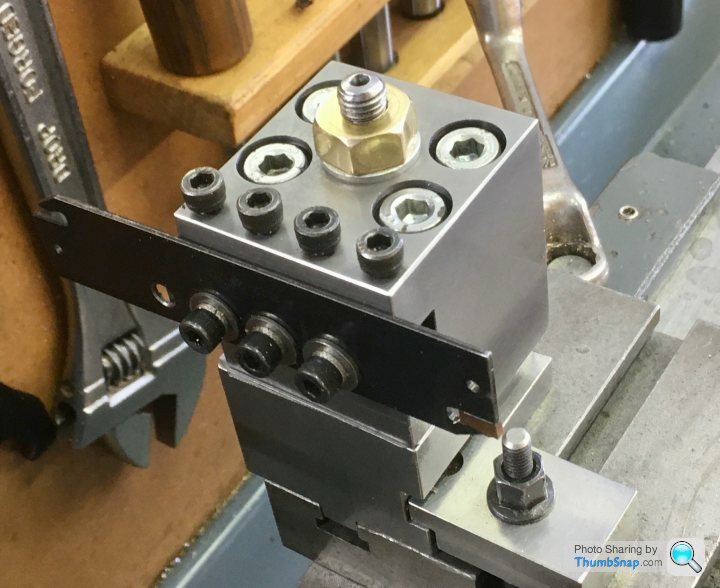
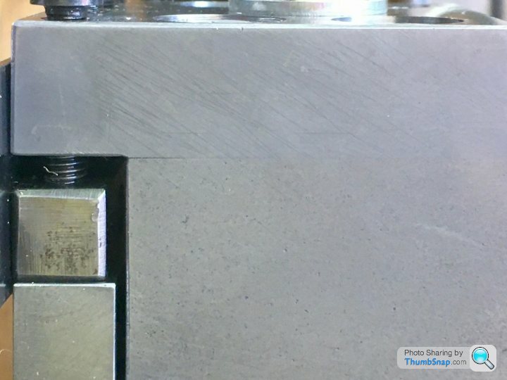
So I've repaired the rear toolpost as suggested with some S275 steel, and M8 capheads: Hi Dr GmJn, From looking at your pictures, you have made a very nice job of the repair on that tool post, I like the toe clamp. A good idea. However I wouldn't tighten the clamp screws down so hard as to distort the new tool holder cap plate ! Another point is that the parting blade extends outside the cross slide, the ideal position is to have the blade above the slideway of the cross slide. This will reduce the cutting forces that want to tip the tool holder towards the tailstock, reducing stability. My last suggestion is that the tool cutting edge is several thou too high. That pip is far too thick just for the overhang to break it off like that, the ideal is that the blade should be dead on centre height. JMTP.
|
| Thread: Tyre Guage DRO - capacitance issues? |
| 03/04/2021 15:05:23 |
Posted by Peter Cook 6 on 02/04/2021 19:28:30:
I use a cheap tyre depth guage as a simple quill DRO on my SX1LP. Apparently it is a capacitance based measuring device.
It works very well - as long as I keep my fingers away from it. If I switch it on or zero it using my fingers I get 0.03-0.05mm "jitter" on the display. Zero it with a non conducting object ( plastic T slot cleaner usually) and all is well. Take the device off the mill and it behaves perfectly as does another similar unit I use for measuring the depth of holes. I suspect the issue is a capacitance effect between me and the ground plane provided by the big lump of iron to which it is screwed. Can anyone explain in a bit more detail how these things work, and make any suggestions as to how I might screen the problem. A bit of brass or plastic between the device and the mill head makes no difference. Check and make sure that the machine/mill frame is truly earthed ! Any capacitive effect is likely due to any residual voltage on the machine frame. FWITW, my mill didn't even have the earth wire connected to the machine in the control box ! The earth wire was just hung in mid air. Luckily it didn't touch anything that could have caused damage.
|
| Thread: Warco 712 Bandsaw |
| 03/04/2021 14:53:08 |
Hi Guys, Having acquired a damaged 6X4 bandsaw and completely refurbished it for very little money, its a machine that with a little care and careful adjustment I wouldn't be without. So I wholeheartedly agree that they are machines that are worthy of attention. Though the pressed sheet metal frame ones are not worth wasting time on. Machine Mart keep a full range of spares for them. Almost forgot ! You can get an idea of blade tension by tapping the blade with a 8" screwdriver handle. When its tight enough you can hear it twang.
Edited By John Baron on 03/04/2021 14:56:42 |
| Thread: Are we being listened to on the phone |
| 03/04/2021 09:33:39 |
Posted by V8Eng on 28/03/2021 23:14:25:
Apparently we might be getting listened to whilst on our phones.
What ever makes you think that the UK, USA and other countries don't listen in ! We have GCHQ and have been spying on ourselves and others for years ! Mobile phones and computers just make it easier ! Why do you think that strong encryption is considered a weapon in the US and unlawful not to give up passwords here in the UK.
|
| Thread: Thread type |
| 30/03/2021 20:03:19 |
Hi Richard, Could be Cycle thread, 5/32 CSI 30 tpi.
|
| Thread: Getting my head round the rotary table |
| 26/03/2021 16:45:13 |
Hi Nick, Guys, My mill has an MT3 spindle, so all I do to centre the RT is put a centre in the mill spindle and use the hole in the middle of the rotary table to locate the centre. Then clamp the table down. As far as centring the work I'll leave that to you.
|
| Thread: 1960's Car Steering Wheel Taper Angle |
| 26/03/2021 16:34:39 |
Posted by Dr_GMJN on 26/03/2021 16:01:06:
Posted by Ian P on 26/03/2021 15:24:28:
Might be changing the subject a little, but... That woodrim steering wheel appears to be a good quality one and whilst I'm all for having a smart looking workshop it looks a little over specified for a mandrel handle. The main point is that it will definitely have a commercial value especially if it has some age. Steering wheels from some 60s (not just exotics/Ferarri's) cars fetch four figures. Ian P Thanks Ian. My late dad fitted it to the MGB in the ‘60’s. It’s one of the unique things I remember about it while being driven around on holiday and to Silverstone in the ‘70’s. When we restored the car in ‘88/‘89, we re-fitted the original wheel. I bought a Moto-Lita wheel for it, but never liked it, so once again fitted the original. My dad always said it needed more rivets to hold the wood to the rim, because of the risk of splintering in a crash. I think there was a standard or something that it didn’t comply with. Having said that, the E-Type wheel has no rivets at all. Anyway, I won’t be selling it, so might as well use it for something useful. I might even re-fit it to the MG at some point. The method of converting it to a hand wheel I’m using, deliberately doesn’t involve any modifications at all. Based on the test I did with it yesterday, I doubt it even needs Loctite if I can get the taper right. Stuff it with Plasticine inside some cling film or a plastic bag ! Though it would be much easier to use a wood plug and a nut and washer through the middle.
This is how I did mine ! It is an old pulley from a washing machine. !
|
| Thread: LG TV ... updated webOS |
| 26/03/2021 09:00:13 |
Hi Guys, My smart TV tries to update itself at exactly 3 pm every morning, that is why is is not allowed to connect to the Internet. I've also got it blocked in the router, but it uses a couple of other IP's which are also blocked. Annoyingly it will connect to the neighbours wireless Internet if it can. I've also got that blocked as well ! It is not made any easier with all these Internet routers giving open access to other devices. This is the reason that people like BT, EE Virgin etc insist you leave your router switched on and insist on you using their router. Your are providing a national network for them at you cost. Note that the ISP can access your router remotely and alter your settings unless you take steps to block them.
|
| Thread: Milling Vice clamps |
| 25/03/2021 19:47:04 |
Hi Guys, Just for the nay sayers, I can remove and replace my vise without all the hassle of setting it up square again ! Which of course also means that I can move the vise anywhere on the mill table and not have to get the gauges out to set it up square. These vises do not have any grooves or slots for alignment keys. It also prevents the screw from digging into the table when the vise moving jaw isn't quite far enough back ! So thanks for your comments, this system works for me, and that is all that matters.
|
| Thread: LG TV ... updated webOS |
| 25/03/2021 11:51:30 |
Hi Guys, Isn't this what Google have done with "Android" ? A platform designed to collect your data, phone numbers, location etc, whether you like it or not ! Yes there are warnings but if you decline them you can't run the application...
|
| Thread: What's the general consensus please? |
| 24/03/2021 16:59:02 |
Hi Guys, JMTPW: I have both a mill and two drills ! I must confess that I could not do without either. The 1/2" Fobco is indespensble and the 5 mm high speed drill gets less use, but it can handle jobs that the other machines can't, Like 1 mm or smaller in PCB's.
|
| Thread: Milling Vice clamps |
| 24/03/2021 16:45:18 |
Hi Chris, Guys, There are five pictures, I've put them in an album, so they don't get lost on my computer.
I've very recently spent some time fitting a DRO and doing some maintenance on the mill. The wooden way covers and the aluminium ones at the back are just a couple of new items.
The long hold down studs are M8 with 8 mm thick clamp plates. The other new item is the stop on the vise at the left. The one on the right is just a piece of 4 mm plate that I had kicking about.
These are just close up pictures of the clamps. You can see the 12 mm precision ground plate. Hope these pictures help. Best Regards: BaronJ:
|
| 24/03/2021 13:44:25 |
Posted by Chris V on 24/03/2021 09:19:53:
Well as expected some great advice thank you all. John Baron, what sort of register did you use for your sub base, a couple of pins screwed into the base? Hi Chris, No my mill is a Chinese copy of the Optimum, similar to the WM16 and others. I used a shallow slot milled across the bottom of the plate and a length of bar screwed in, it is milled to be just wide enough to drop into the table slots anywhere I choose. The base thickness was simply because I had a piece of precision ground plate of suitable size, and it is a lot harder to distort than thinner plate. It also has the advantage that I can slide the vise to one side and place the rotary table on the mill as well, so I have use of both if I need to. The vise hold downs are machined from square bar and use M6 cap screws in counterbores to secure them. The plate is held down in the usual way with "T" nuts, studs and plates, the plates supported on alloy pillars sitting in the table slots. I can take a picture if you want !
Edited By John Baron on 24/03/2021 13:47:25 |
| 23/03/2021 14:35:50 |
Hi Guys, I also bought one of the type ll vises as sold by ARC. These have slots along the length of the vise and can accommodate more clamps if felt necessary. I mounted mine on a ground flat 12 mm thick plate with four hold downs for the vise and four "T" nuts and studs to hold the plate. I put a register on the bottom so that the vise can be removed and put back in the mill table knowing that it will be dead square. My only criticism of the vise is that I've discovered that the rear jaw is not true vertically. I've only found out recently. The top and front edge is OK as is the slides, however one side is a few thou smaller than the top on one side. I initially I thought that this was a vertical tram error but checking with a square it seems not to be.
|
| Thread: 3-Jaw Chuck not running true - how to fix |
| 21/03/2021 19:07:59 |
Hi Guys, This how I get around run out issues with my three jaw chuck. Note, you still have to put something in the jaws to tension them.
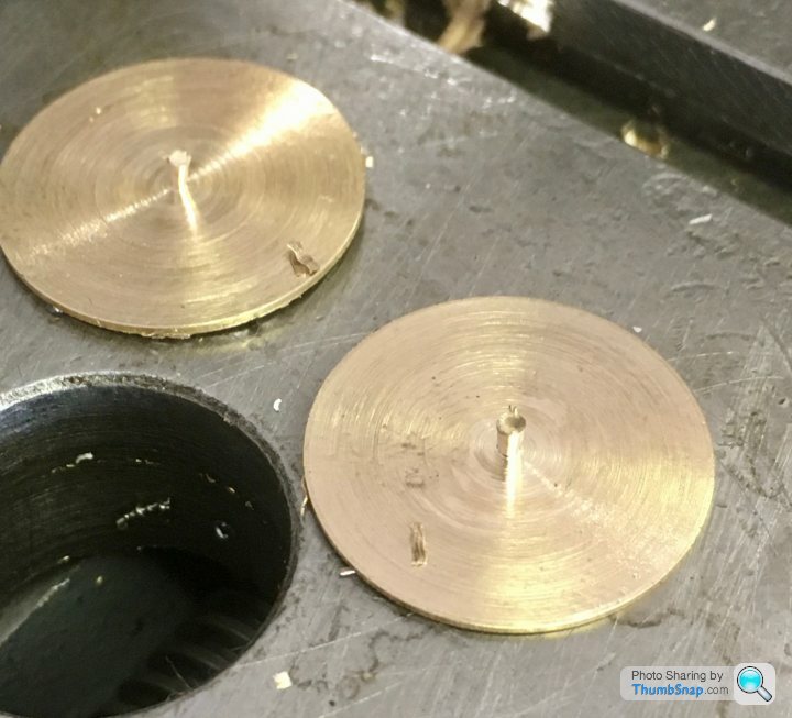
I made three alloy pieces, and drilled and threaded the jaws M6. As you can see from the pictures I use CSK screws to secure them. I made several jaws so that I can simply replace them as needed.
|


Magazine Locator
Want the latest issue of Model Engineer or Model Engineers' Workshop? Use our magazine locator links to find your nearest stockist!
Sign up to our Newsletter
Sign up to our newsletter and get a free digital issue.
You can unsubscribe at anytime. View our privacy policy at www.mortons.co.uk/privacy
Latest Forum Posts
- *Oct 2023: FORUM MIGRATION TIMELINE*
05/10/2023 07:57:11 - Making ER11 collet chuck
05/10/2023 07:56:24 - What did you do today? 2023
05/10/2023 07:25:01 - Orrery
05/10/2023 06:00:41 - Wera hand-tools
05/10/2023 05:47:07 - New member
05/10/2023 04:40:11 - Problems with external pot on at1 vfd
05/10/2023 00:06:32 - Drain plug
04/10/2023 23:36:17 - digi phase converter for 10 machines.....
04/10/2023 23:13:48 - Winter Storage Of Locomotives
04/10/2023 21:02:11 - More Latest Posts...
- View All Topics
Support Our Partners


Shopping Partners
Subscription Offer

Latest "For Sale" Ads
- Reeves** - Rebuilt Royal Scot by Martin Evans
by John Broughton
£300.00 - BRITANNIA 5" GAUGE James Perrier
by Jon Seabright 1
£2,500.00 - Drill Grinder - for restoration
by Nigel Graham 2
£0.00 - WARCO WM18 MILLING MACHINE
by Alex Chudley
£1,200.00 - MYFORD SUPER 7 LATHE
by Alex Chudley
£2,000.00 - More "For Sale" Ads...
Latest "Wanted" Ads
- D1-3 backplate
by Michael Horley
Price Not Specified - fixed steady for a Colchester bantam mark1 800
by George Jervis
Price Not Specified - lbsc pansy
by JACK SIDEBOTHAM
Price Not Specified - Pratt Burnerd multifit chuck key.
by Tim Riome
Price Not Specified - BANDSAW BLADE WELDER
by HUGH
Price Not Specified - More "Wanted" Ads...
Get In Touch!
Do you want to contact the Model Engineer and Model Engineers' Workshop team?
You can contact us by phone, mail or email about the magazines including becoming a contributor, submitting reader's letters or making queries about articles. You can also get in touch about this website, advertising or other general issues.
Click THIS LINK for full contact details.
For subscription issues please see THIS LINK.
Digital Back Issues


Donate

 Register
 Log-in
Model Engineer Magazine
- Percival Marshall
- M.E. History
- LittleLEC
- M.E. Clock

ME Workshop
- An Adcock
- & Shipley
- Horizontal
- Mill

Subscribe Now
- Great savings
- Delivered to your door

Pre-order your copy!
- Delivered to your doorstep!
- Free UK delivery!