Forum sponsored by:

ML7 Topslide limitations
| Mike Poole | 08/12/2013 15:36:54 |
 3676 forum posts 82 photos | The ML7 and ML7R topslide does not allow a greater than 65 deg rotation as standard. Is there a classic work around for this problem that I have missed, converting to the S7 assembly is an expensive solution. Mike Edited By Michael Poole on 08/12/2013 15:37:21 |
| old Al | 08/12/2013 16:08:56 |
| 187 forum posts | you can rearrange the position of the two clamp bolts to get more angle. You have to lift the topslide off to move the bolts. Bit fussy, but it can be done |
| Mike Poole | 08/12/2013 17:05:28 |
3676 forum posts 82 photos | Hi Al, Even if I remove the swivel boss I can not find a position where two bolts can pick up a tee slot because the slot in the top slide base is wider than the cross slide. Mike |
| old Al | 08/12/2013 18:21:07 |
| 187 forum posts | Hi Michael I will have to have a look tomorrow. I have had to do something similar, I just cant remember!
Have you got reverse on your lathe?
Alan. |
| Mike Poole | 08/12/2013 19:00:26 |
3676 forum posts 82 photos | Applying a bit of lateral thinking I think my vertical slide has some possibilities, swing it to a horizontal position and angle the base to give required facing angle, bit of a fiddle to set tool height but for a one off it's not too bad. Maybe the S7 slide conversion is the only practical solution. Mike |
| anthony smith 4 | 08/12/2013 19:15:54 |
| 10 forum posts | TO ALLOW GREATER ROTATION OF TOP SLIDE MAKE A SUB BASE OF 3/8 THICK PLATE ABOUT 4.5INS SQUARE WITH A HOLE BORED TO SUITE TOP SLIDE SPIGGET. FIXED TO CROSS SLIDE WITH COUNTERSUNK SOCKET SCREWS MILL CURVED SLOTS TO SUITE TOP SLIDE FIXINGS.IT WILL THEN BE NECESSARY TO USE SMALLER TOOLS |
| John Stevenson | 08/12/2013 19:17:38 |
 5068 forum posts 3 photos | When I owned a ML7 some years ago I moved the topslide round to the maximum position before the handle fouled the cross slide then worked out decent position where it had plenty of room and drilled and tapped two 1/4" BSF holes.
Worked for me but I dare say the flat earth society would have a baby because I drilled a Myford. Sorry they are not something to be prayed to every Sunday, obviously Myfords cocked up or people would not need to modify the machine to do what it should have been designed to do. |
| Andrew Moyes 1 | 08/12/2013 20:15:02 |
| 158 forum posts 22 photos | Ian Bradley in Myford ML7 Lathe Manual shows a solution using a sole plate interposed between the top slide and cross slide. The down side is that it reduces the size of tool that can be used to about 5/16". I vaguely remember using a tool mounted on the swivelling vertical slide to get around the problem. I can't remember now how I did it - perhaps this will jog someone else's memory. Will post again if it comes to me! Andrew M |
| Andrew Moyes 1 | 08/12/2013 21:24:23 |
| 158 forum posts 22 photos | I remember now. It was the very first thing I made when I bought an ML7; a Stuart centrifugal pump. I thought it would be an easy first project until I needed to take a facing cut across the blades. They are required to be at a slight angle, not possible with the standard topslide. The solution was to use the vertical slide with its table parallel to the axis of the lathe. The top of the vertical slide was rotated slightly towards the headstock by the required angle and the tool was mounted in a vice on the slide, pointing towards the headstock. Andrew M |
| Bubble | 08/12/2013 21:41:04 |
| 75 forum posts 6 photos | Hello Michael This solution was described by a Mr Beecroft in ME in about 1955 It works fine for screwcutting but watch-out for excessive tool overhang on the top slide which can give an upward force on the assembly. A refinement would be two long tee-nuts in the cross slide slots, with the two side- bars attached to them with studs, this would provide vertical location. Jim
|
| Mike Poole | 08/12/2013 21:59:22 |
3676 forum posts 82 photos | Thanks for the input gentlemen, it would seem that Johns solution of drilling the cross slide would be the most convenient on a regular requirement to use these small angles. The vertical slide solution that Andrew proposed is the one I shall use for the one off job I have in mind as it is a quick and dirty setup with no need to make anything. I will probably get round to making a sub base but as I find my Dickson tool post most useful and the sub base would negate its use this would only be fitted on demand. Looking at drilling the cross slide for Johns solution there is not much room to drill without being very close to a tee slot so although I could live with two neatly tapped holes if the tee slot broke this would annoy me forever like drilling holes in the table on a drilling machine or milling the table on the mill or drilling a machine vice. Mike |
| Mike Poole | 08/12/2013 22:09:00 |
3676 forum posts 82 photos | While I was typing, a solution like the one Jim has just posted came into my mind, it must be the power of suggestion at work. With the refinements Jim suggests this could well be the top answer for a leave it in place answer, it would only need to be removed for travelling steady fitment. Mike |
| Robbo | 09/12/2013 10:36:26 |
| 1504 forum posts 142 photos | Further to Bubble's post, this is Mr Beecraft's original drawing. Just for fun.
|
| anthony smith 4 | 09/12/2013 15:08:20 |
| 10 forum posts | RE MR BEECROFTS DRAWING THIS DOES NOT APPEAR TO PREVENT THE TOP SLIDE FEED DIAL FOWLING THE CROSS SLIDE DIAL.THE SUB BASE OF 3/8 THICKNESS WILL PREVENT THIS .THE PLATE SHOULD BE 4.75" SQUARE AND NOT 4.5" AS I SUGGESTED |
| Alan Jackson | 09/12/2013 17:14:53 |
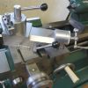 276 forum posts 149 photos | I have just added some photos of a Lever Locking Top slide conversion for a Myford ML7. I made this a few years ago. I know as John S. has just referred to that Myford owners do not like to modify their machines but in my opinion it is well worth doing. I have a Colchester Chipmaster lathe with a similar conversion and would not like to go back to the original arrangement trying to access nuts in slots filled with swarf etc. Alan |
| Bubble | 09/12/2013 18:11:06 |
| 75 forum posts 6 photos | Anthony True, I can "only" go to 80 degrees. I did say it was fine for screwcutting. In 50+ years with an ML7 I have never needed to go "squarer", that's what the cross slide is for! I think the loss of 3/8" height is a bigger limitation, especially with quick-change toolposts. Jim ps please take your caps lock off! |
| Mike Poole | 09/12/2013 23:00:55 |
3676 forum posts 82 photos | Thankyou gentlemen for all your contributions, I will most likely use more than one solution as there are pros and cons for all of them, Michaels copy attachment could be very useful with suitable templates for large radius curves and other forms. Mike |


Please login to post a reply.
Magazine Locator
Want the latest issue of Model Engineer or Model Engineers' Workshop? Use our magazine locator links to find your nearest stockist!
Sign up to our Newsletter
Sign up to our newsletter and get a free digital issue.
You can unsubscribe at anytime. View our privacy policy at www.mortons.co.uk/privacy
Latest Forum Posts
- *Oct 2023: FORUM MIGRATION TIMELINE*
05/10/2023 07:57:11 - Making ER11 collet chuck
05/10/2023 07:56:24 - What did you do today? 2023
05/10/2023 07:25:01 - Orrery
05/10/2023 06:00:41 - Wera hand-tools
05/10/2023 05:47:07 - New member
05/10/2023 04:40:11 - Problems with external pot on at1 vfd
05/10/2023 00:06:32 - Drain plug
04/10/2023 23:36:17 - digi phase converter for 10 machines.....
04/10/2023 23:13:48 - Winter Storage Of Locomotives
04/10/2023 21:02:11 - More Latest Posts...
- View All Topics
Support Our Partners


Shopping Partners
Subscription Offer

Latest "For Sale" Ads
- Reeves** - Rebuilt Royal Scot by Martin Evans
by John Broughton
£300.00 - BRITANNIA 5" GAUGE James Perrier
by Jon Seabright 1
£2,500.00 - Drill Grinder - for restoration
by Nigel Graham 2
£0.00 - WARCO WM18 MILLING MACHINE
by Alex Chudley
£1,200.00 - MYFORD SUPER 7 LATHE
by Alex Chudley
£2,000.00 - More "For Sale" Ads...
Latest "Wanted" Ads
- D1-3 backplate
by Michael Horley
Price Not Specified - fixed steady for a Colchester bantam mark1 800
by George Jervis
Price Not Specified - lbsc pansy
by JACK SIDEBOTHAM
Price Not Specified - Pratt Burnerd multifit chuck key.
by Tim Riome
Price Not Specified - BANDSAW BLADE WELDER
by HUGH
Price Not Specified - More "Wanted" Ads...
Get In Touch!
Do you want to contact the Model Engineer and Model Engineers' Workshop team?
You can contact us by phone, mail or email about the magazines including becoming a contributor, submitting reader's letters or making queries about articles. You can also get in touch about this website, advertising or other general issues.
Click THIS LINK for full contact details.
For subscription issues please see THIS LINK.
Digital Back Issues


Donate

 Register
 Log-in
Model Engineer Magazine
- Percival Marshall
- M.E. History
- LittleLEC
- M.E. Clock

ME Workshop
- An Adcock
- & Shipley
- Horizontal
- Mill

Subscribe Now
- Great savings
- Delivered to your door

Pre-order your copy!
- Delivered to your doorstep!
- Free UK delivery!
All Forum Topics > Manual machine tools > ML7 Topslide limitations