Forum sponsored by:

Wheel Cuting thin tooth?
| Peter Bell | 05/01/2012 18:11:21 |
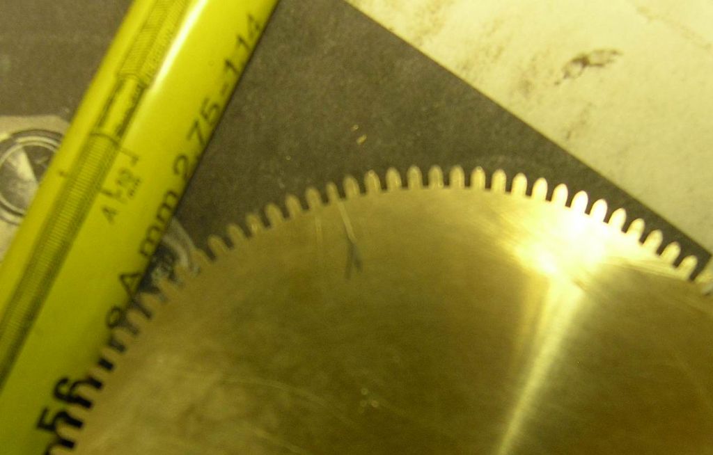
| 399 forum posts 167 photos | Been cutting some 115t 0.75m wheels using a Thorntons cutter. I calculated the blank dia using the formula (N + 2.76) M which gave a blank of 88.32mm or 3.477" but I have ended up with a thin tooth on each wheel which indicates a slightly small blank?(I think?) I cut the teeth until there was just a tiny witness on the tip as I have done before but a feel bit dissapointed as I have ruined 4 wheels made from 5/16 thick engraving brass.
Next time I will try a dummy run on some 1/8" which I have plenty of!
Are my calcs correct or have I missed something?
Peter |
| Peter Bell | 05/01/2012 19:14:54 |
| 399 forum posts 167 photos | Hi,
I have a thin tooth on each blank, rest of the teeth look fine, Thats what made me think that I have size problem with the blank. I use my Super 7 with a milling spindle on the cross slide to cut the teeth, cutter running at about 3000rpm.
Peter |
| Peter Bell | 05/01/2012 19:32:22 |
| 399 forum posts 167 photos | Direct indexing from a plate on the end of the spindle, made the plate last year using a rotary table, drilled twice so that we could check for errors. Suppose we could make another plate easier this year with our KX3, if we had a suitable size of disc. Thinking about it. You could be right, this is the first time it has been used!
What effect would there be if the blank was slightly small? Last cut wheels ages ago and think I had problems with a blank size then.
Peter |
| Andrew Johnston | 05/01/2012 19:44:40 |
 7061 forum posts 719 photos | If the blank was a bit small, but the indexing was correct, then you'd end up with 115 teeth equally spaced, with all the teeth (or gaps) incorrect, but the same. If the indexing is slightly wrong, irrespective of blank size, you'll end up with the last tooth/gap being different. Regards, Andrew |
| Harold Hall 1 | 05/01/2012 19:55:58 |
| 418 forum posts 4 photos | I agree with Michael it is an indexing problem. No matter what the blank size is the teeth should still be equally spaced. If you are confident that the indexing plate is correct having made two and checked one against the other then something must have moved during the process. This could be either the wheels, the indexing plate or the plates detent. In this case you should also have a larger tooth somewhere around the wheel, have you checked this? Just possibly, you did not fully engage the detent, this would also show a larger tooth against the smaller tooth. Harold |
| Tel | 05/01/2012 21:08:42 |
 157 forum posts 28 photos | Yep, almost certainly a slight slip with the indexing - I had the same thing happen on a 40dp wheel about a year ago - one thin tooth, one fat tooth beside it! (N + 2.76) M tho? I use (N+2) M - same as DP's - works ok for me - I cut 3 x Mod 1 45t's yesterday, in fact - I'll get a pic of 'em later. 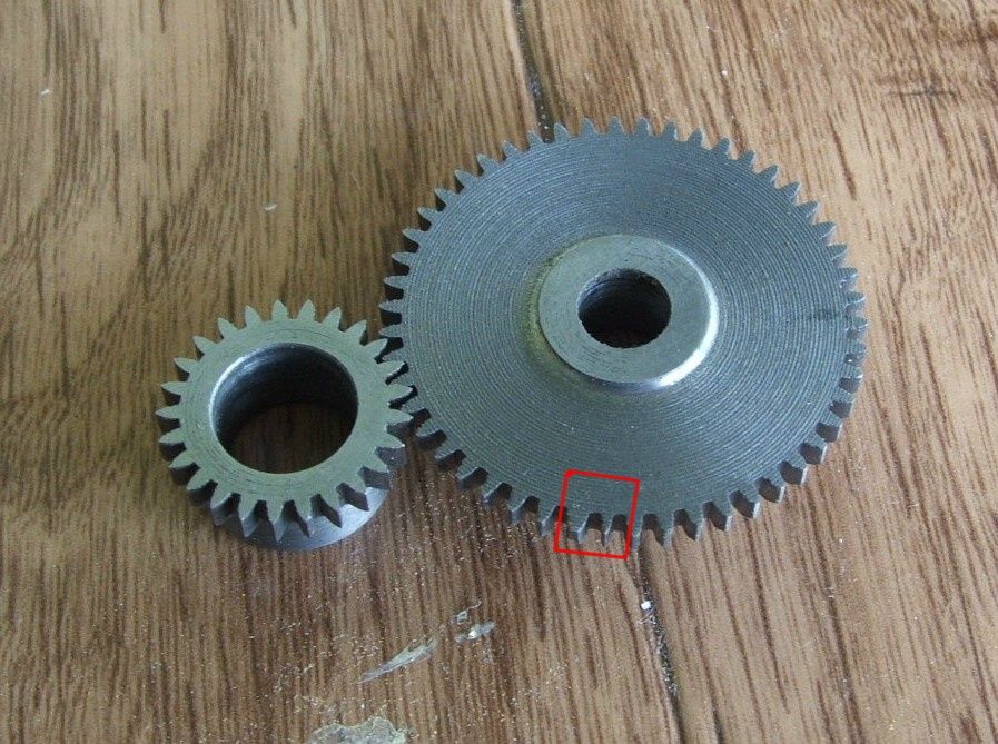 |
| Peter Bell | 05/01/2012 21:12:28 |
| 399 forum posts 167 photos | Just checked the indexing plate by winding the cord from a B&W Dro around the chuck and indexing around the plate and we found the error to be less that 2 thou between divisions so that doesnt seem too bad. The detent is a fairly well pushed into the hole in the plate as it is mounted on a piece of 1" x 1/8" bar.
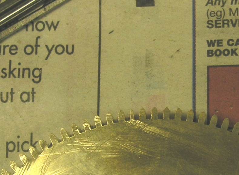
Perhaps something moved but funny how it is just the one tooth on all wheels, taken some pics (sorry for the poor quality!) to show what I mean.
I have a feeling that I had this problem once before but cannot recall what it was, must admit that I thought that the blank size was fairly critical but getting to tired to think
Peter
  |
| Tel | 05/01/2012 21:20:04 |
157 forum posts 28 photos | It's on all wheels? That seems to say blank size error then. Silly queation, but have you counted the actual teeth it's cutting? |
| Harold Hall 1 | 05/01/2012 22:31:48 |
| 418 forum posts 4 photos | Are you saying that you cut four gears individually and they all have the same problem, I thought from your original post that you had stacked the four blanks and cut them at the same time. If you cut them individually it certainly points to a problem with you dividing plate. I am in the process of making one of John Parslow's clocks and he deliberately cuts wheels, having the same number of teeth, on differing blank sizes to achieve the clearances required. Having cut the wheels I can confirm that they all work OK, Teeth all the same size on any one wheel. Obviously, the teeth will be slightly wider on those cut on a larger blank Harold |
| Andrew Johnston | 05/01/2012 22:43:49 |
7061 forum posts 719 photos | Err, I seem to recall that clock wheels, using a cycloidal tooth form, use a different formula to calculate the OD, than that used for gears using involute tooth forms. As Harold says, if four separate gears have been cut, all with the same error, it points to a systemic error in the indexing. Try a new blank, any size, and cut the first tooth, to any depth. Then index round all the other teeth, without actually cutting any more teeth. Once back to the start the cutter should pass through the original cut without cutting any more material. If it doesn't then you definitely have an indexing problem. Regards, Andrew |
| Richard Parsons | 06/01/2012 05:55:37 |
 645 forum posts 33 photos | Peter have a look at your calculations for the rotary table.
Now 360/115 is 3.130434782608 ….. Degrees per hole. How is your rotary table calibrated? What is the error per hole in terms of that value?. Supposing your table allows you to measure to1/8th (0.125) of a degree. The second hole you drilled in your division plate would be 0.005434 etc of a degree out of position. The next hole would be 0.010868 of a degree inaccurate and so on for all 114 holes (the first hole is spot on) the accumulated error would be 0.619562 etc of a degree adrift. Now the 115 divisions is 3° 7’ 49.565” of arc. If your rotary tables will allow you to get to 10’ of arc then the second hole would be 2.1739.. etc minutes of arc adrift. So after 114 holes the error would be 4.13043 degrees adrift. But all is not lost. There is a very good way of making such a plate. Firstly you need a strip of thin steel. I use second hand metal case strapping. You then need to make a 2 hole drill jig with a suitable distance between holes and a pin which is a nice push fit into the holes on the jig. Use it to drill a hole in your strip. Move the hole you have just drilled to the second hole in the jig and drill another hole. Repeat this until you have drilled 116 holes. Measure the distance between the 1st and the last hole. This will give you the circumference of the loop you are going to make. Make a loop with the 116th hole lined up over the 1st hole and join things together. Now make a wooden disk whose diameter is that of the loop. I do this by rough sawing over size and then turn to size gently. Ok now you have a drum of 115 holes. The holes will have errors of +-0.001” but this will not always be in the same direction and will tend to average things out!. Hope it helps Rdgs Dick Edited By Richard Parsons on 06/01/2012 06:02:02 |
| Peter Bell | 06/01/2012 07:51:53 |
| 399 forum posts 167 photos | Thanks everyone for all the input. I cut the wheels individually to try and avoid any errors, perhaps I should looked at them before carrying on! I wondered about the error from the rotary table adding up but when we measured the distance betwen each hole we found very little error but never used this plate before so it is a bit unknown.
When I made most of my plates the divisions were calculated on a BBC computer and they seem ok. Thanks for reminding me about the strip method, used that initially and it worked fine but then I bought a rotary table and the BBC computer came along
Will cut more wheels using this division plate soon and report back, willalso try some different size blanks, all interesting stuff but thought I had it cracked!
Regards Peter |
| Richard Parsons | 06/01/2012 08:19:04 |
645 forum posts 33 photos | Peter Remember that using the rotary table the errors between individual holes are very small. But they accumulate. That is the error between each pair of holes is 0.005434” but the error between the first and third hole is 0.010868” and so on. It only shows up at on the very last tooth. Rdgs Dick |
| Tel | 06/01/2012 08:25:08 |
157 forum posts 28 photos | AHA! The magic phrase! Rotary table! I've never had much luck with gears using mine. My gear cutting is all done on my version of Harold's whiz-bang dividing head! 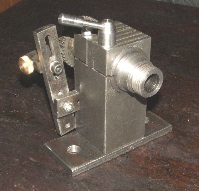 |
| Niloch | 06/01/2012 10:40:35 |
| 371 forum posts | Peter, My initial experiences at wheel cutting were much the same as yours. I had chosen to make John Wilding's 'Large Wheel' skeleton clock with 290 teeth on the large wheel so it was quite a worry, I gave up, managed to get a good price on eBay for my Myford dividing head which was still in its original carton with the addition of a further plate from Mr Stevenson to fund the purchase of the Divisionmaster device. I already had a rotary table and the means to fix it in the headstock mandrel. I can now actually conduct a conversation with someone whilst wheel cutting, whereas, with the traditional dividing head it only needed the telephone to ring or a knock on the door to ensure a thin tooth! |
| Jens Eirik Skogstad | 06/01/2012 19:41:09 |
 400 forum posts 22 photos | Indexing problem can be caused by:
Wrong division in the indexing plate.
Wrong division in the gear wheel.
Loose fitted indexing plate or gearwheel.
Loose fitted indexing arm/pin.
Loose bearing.
Loose worm wheel in the indexinghead/table
Not correct pitch distance in the worm wheel in all places from the beginning to the end of the thread. (very rare)
Also all division must be absolute correct divided both in indexing plate and gear wheel and no play in the indexing head except the clearance can be a bit loose between worm wheel and gear wheel hence never rotate past the hole before return back to the hole and lock there with indexing pin. The bearing will have some resistance when you turn around the shaft in the indexinghead to prevent there is play and no shaking under work. Turn the indexing arm slow until the indexing pin is locked in the indexing plate.
Edited By Jens Eirik Skogstad on 06/01/2012 19:43:37 |
| Jens Eirik Skogstad | 06/01/2012 19:54:30 |
400 forum posts 22 photos | I can see the space between teeth is in correct size before the last teeth is thin, can be caused by wrong sized blank wheel with other wrong calculated gear wheel. The gear wheel with envolvent teeth and gear with cycloidal teeth has difference formula to calculate the correct size of blank wheel. Check again in case you has been overlocked in calculating the gear size. |
| john jennings 1 | 06/01/2012 20:02:09 |
| 69 forum posts | Peter, 1.The size of the blank will give stubby or elongated teeth if incorrect. If over large the cutter might just auto trim the teeth to size. 2. You say you are directly indexing, that is your dividing plate has 115 holes. If so I would have thought that the error would have been obvious on the plate with a larger or smaller gap between two holes (check with dividers). 3. I would have thought you would have noticed this just as you observe the thin tooth. So what is the cause? If your 4 wheels are essentially identical I can't believe that rotational slippage is going to be that reproducible or affect only one tooth per wheel. Is there some form of back lash in the system which gives an incorrect position : I would guess on the first or final cut ( Do you know which is the thin tooth in order of cutting first/last tenth etc?) hope this may help your investigation John |
| Billy Mills | 06/01/2012 20:24:23 |
| 377 forum posts | Peter
Did you take 360/115 as the increment between holes then make a table of multiples when making the plate? That could explain the problem as the rounding error would accumulate around the cut gear. The error in the plate would not be that visible until the last tooth is cut.
If the final error was around 1/10 of the spacing we only need a step error of 0.003 degrees per step.
Another way is to calculate the individual tooth position as n*360/115, rounding errors should then be well distributed.
Billy.
|
| Peter Bell | 06/01/2012 20:54:21 |
| 399 forum posts 167 photos | Thanks everyoner for all the comments.
Just measured the teeth and they are of equal thickness apart from the thin one. We thought of using dividers to check the division plate but felt that it would be easier and more accurate using the BW Electronics DRO and wind the cord from it around the 3 jaw chuck. Went round the plate twice but could not find any error of more than a thou or two between the holes.
I like the direct indexing as there is less chance of making a mistake and you can feel as well as hear the dentent going into the plate. It is dead tight with no slipping/backlash anywhere.
Did not see the problem when I took the cut wheel from the mandrel as I was quite pleased at how good it looked, must clean my glasses more often.
Just cut a disc to do a trial, pondering it I should make it slightly larger or the dead size from the formula.
Next time I will examine the blank before removing it from the mandrel so that I can see where the thin tooth lines up with the plate---if there is a thin tooth!
Peter |
Please login to post a reply.
Magazine Locator
Want the latest issue of Model Engineer or Model Engineers' Workshop? Use our magazine locator links to find your nearest stockist!
Sign up to our Newsletter
Sign up to our newsletter and get a free digital issue.
You can unsubscribe at anytime. View our privacy policy at www.mortons.co.uk/privacy
Latest Forum Posts
- hemingway ball turner
04/07/2025 14:40:26 - *Oct 2023: FORUM MIGRATION TIMELINE*
05/10/2023 07:57:11 - Making ER11 collet chuck
05/10/2023 07:56:24 - What did you do today? 2023
05/10/2023 07:25:01 - Orrery
05/10/2023 06:00:41 - Wera hand-tools
05/10/2023 05:47:07 - New member
05/10/2023 04:40:11 - Problems with external pot on at1 vfd
05/10/2023 00:06:32 - Drain plug
04/10/2023 23:36:17 - digi phase converter for 10 machines.....
04/10/2023 23:13:48 - More Latest Posts...
- View All Topics
Support Our Partners


Shopping Partners
Subscription Offer

Latest "For Sale" Ads
- Reeves** - Rebuilt Royal Scot by Martin Evans
by John Broughton
£300.00 - BRITANNIA 5" GAUGE James Perrier
by Jon Seabright 1
£2,500.00 - Drill Grinder - for restoration
by Nigel Graham 2
£0.00 - WARCO WM18 MILLING MACHINE
by Alex Chudley
£1,200.00 - MYFORD SUPER 7 LATHE
by Alex Chudley
£2,000.00 - More "For Sale" Ads...
Latest "Wanted" Ads
- D1-3 backplate
by Michael Horley
Price Not Specified - fixed steady for a Colchester bantam mark1 800
by George Jervis
Price Not Specified - lbsc pansy
by JACK SIDEBOTHAM
Price Not Specified - Pratt Burnerd multifit chuck key.
by Tim Riome
Price Not Specified - BANDSAW BLADE WELDER
by HUGH
Price Not Specified - More "Wanted" Ads...
Get In Touch!
Do you want to contact the Model Engineer and Model Engineers' Workshop team?
You can contact us by phone, mail or email about the magazines including becoming a contributor, submitting reader's letters or making queries about articles. You can also get in touch about this website, advertising or other general issues.
Click THIS LINK for full contact details.
For subscription issues please see THIS LINK.
Digital Back Issues


Donate

 Register
 Log-in
Model Engineer Magazine
- Percival Marshall
- M.E. History
- LittleLEC
- M.E. Clock

ME Workshop
- An Adcock
- & Shipley
- Horizontal
- Mill

Subscribe Now
- Great savings
- Delivered to your door

Pre-order your copy!
- Delivered to your doorstep!
- Free UK delivery!
All Forum Topics > Clocks and Scientific Instruments > Wheel Cuting thin tooth?