Forum sponsored by:

Potty Overcrank 4415
| JasonB | 20/10/2011 19:38:29 |
 25215 forum posts 3105 photos 1 articles | Couple of things that don't look right on the ME drawings when compared to the originals.
Fig 19 Crankshaft Bearings, the 5mm dimensions are shown but not the machined square flat they refer to.
Part 42 Eccentric Sheaves, Shown with 10mm bore as original drawings but crankshaft is shown as 12mm dia
Part 21 Outer Guide bar bearing, size of holes not shown
Part 23 Crankshaft, No length for the reduced dia and or unreduced dia at each end shown. Probably better to show the length of the bearing surface.
J
Edited By JasonB on 20/10/2011 19:41:28 Edited By JasonB on 20/10/2011 19:53:57 |
| Tel | 20/10/2011 20:55:23 |
 157 forum posts 28 photos | "Part 42 Eccentric Sheaves, Shown with 10mm bore as original drawings but crankshaft is shown as 12mm dia" Hmmmm ..... a 'tight press fit'?  |
| Stewart Hart | 20/10/2011 22:04:20 |
 674 forum posts 357 photos | I'll put my hand up to part 42:- 10mm bore 12mm shaft, I changed the crank shaft to 12mm but didn't catch everything this impacted on.
The others are different than my drawing ?.
Stew
|
| Stewart Hart | 21/10/2011 07:23:36 |
674 forum posts 357 photos | Part 18 Bearing Cap M4 thread missing
Part 20 Oiler M4 Thread Missing
I've checked my original drawing out and they are correct.
For some reason the graphic artist insists on putting the diameter symbol in even where it isn't required, they are probably not conversant with engineering drawing practice.
Don't know what process they go through for publishing but I guess they copy them over then because they have reduced the size add larger text, but this isn't done as diligently as could be. If I submit another article I'll probably use a bigger font size this will reduce the opportunity for error.
Perhaps David would like to comment on this.
Any one wanting a PDF copy of my original drawing, just send me a PM and I'll be happy to provide them.
Stew
|
| JasonB | 21/10/2011 07:28:21 |
25215 forum posts 3105 photos 1 articles | Part 19 on your drawing shows a 5mmx5mm flat machined on the top of the bearing, I assume the oiler bears against this to stop rotation. In ME the two 5mm dimensions are given but the square is not shown.
Part 21 I think is different anyway but the 4 holes are not sized
Part 23 Can't find a pdf for that but it could do with teh added dimension.
Also on the big end caps one view shows a central 3mm hole but its not shown from the opposite end or as hidden detail from the side. Is this meant to be the dowel hole in the conrod?
Oh and the wrong photo has been used in pic 43.
While I'm on it reads as though you bore the bigend hole in the conrod and then saw off the cap, is that correct as I've always split the part first before boring as that way there is no risk od squashing the bearing when tightening the bigend.
J |
| Stewart Hart | 21/10/2011 07:56:44 |
674 forum posts 357 photos | Jason
Thanks for the input, it gives people the chance to get things right if they are intending building this engine ther's nothing worse than starting off on a project and being led up the garden path by a dodgy drawing.
Q1:- Part 19 on your drawing shows a 5mmx5mm flat machined on the top of the bearing, I assume the oiler bears against this to stop rotation. In ME the two 5mm dimensions are given but the square is not shown.
A1:- Part 19 are the crank shaft bearing, they don't have this flat. The split big end bearing has this flat. don't know why this is shown on part 19 its not on the origonal.
Q2:- Part 21 I think is different anyway but the 4 holes are not sized
A2:- They should be M 2.5 again they are on the original
Q3:- Part 23 Can't find a pdf for that but it could do with teh added dimension.
A3:- I left the size off on purpose as it will depend on the size of the flywheel fitted.
Q4:- Also on the big end caps one view shows a central 3mm hole but its not shown from the opposite end or as hidden detail from the side. Is this meant to be the dowel hole in the conrod?
A4:- That could be me, its an optional oil hole.
Oh and the wrong photo has been used in pic 43.
Yes I noticed that
While I'm on it reads as though you bore the bigend hole in the conrod and then saw off the cap, is that correct as I've always split the part first before boring as that way there is no risk od squashing the bearing when tightening the bigend.
That will become clear in the next part.
Stew00
|
| JasonB | 21/10/2011 16:47:17 |
25215 forum posts 3105 photos 1 articles | A1:- Part 19 are the crank shaft bearing, they don't have this flat. The split big end bearing has this flat. don't know why this is shown on part 19 its not on the origonal.
This is the part, shows flats, the ME one has the 5mm dims but no flat
 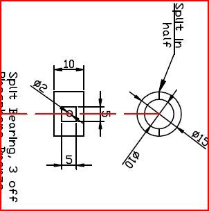 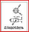 Don't know why you say the big end bearings have flats, would have thought they just needed a hole for the dowel pin but will wait for the next issue. J |
| Stewart Hart | 21/10/2011 18:23:17 |
674 forum posts 357 photos | Quote:- Don't know why you say the big end bearings have flats, would have thought they just needed a hole for the dowel pin but will wait for the next issue. Quaote:-
Reply:- It acts like a key to stop the bearing turning, we use to have some Taylor and Challen draw presses that used this system on the main crank shaft bearings, so I used the method her.
Stew
|
| JasonB | 21/10/2011 18:32:10 |
25215 forum posts 3105 photos 1 articles | Ah are you saying the dowel pin bears against the flat to stop the bearing rotating? I can see that working.
Though I have usually seen a hole in the bearing to take a fixed pin or if the hole is at the top then the wick tube from the oiler is taken through the cap and into this hole so preventing the bearing from turning.
J |
| Stewart Hart | 21/10/2011 18:50:51 |
674 forum posts 357 photos | Thats correct.
I've seen the other methods also, don't know what advantage the flat on the bearing would have i just remembered it and decided to use it.
Taylor and Challen didn't use it on all their presses, we had about ten of this type and they were all the same.
Stew
|
| Grahame Chambers 2 | 31/10/2011 12:23:31 |
| 4 forum posts | Posted by Stewart Hart on 21/10/2011 07:23:36: Part 18 Bearing Cap M4 thread missing Part 20 Oiler M4 Thread Missing I've checked my original drawing out and they are correct. For some reason the graphic artist insists on putting the diameter symbol in even where it isn't required, they are probably not conversant with engineering drawing practice. Don't know what process they go through for publishing but I guess they copy them over then because they have reduced the size add larger text, but this isn't done as diligently as could be. If I submit another article I'll probably use a bigger font size this will reduce the opportunity for error. Perhaps David would like to comment on this. Any one wanting a PDF copy of my original drawing, just send me a PM and I'll be happy to provide them. Stew Speaking as the illustrator for ME & MEW: Part 18 - The PDF I was supplied with doesn't show the M4 thread. Part 20 - The same as above. If a part is round I add a diameter symbol - if that's strictly incorrect for engineering I apologize. When I receive the PDF's (or DWG/DXF etc.) they're opened in Adobe Illustrator, I resize the diagrams to suit the magazine layout, adjust line weights & change the font to make them uniform throughout the magazine. The diagrams then go to David to check, if he gives me any corrections I change what's needed, & then they go to the magazine designer. I'm not an engineer & I'm not a draughtsman, I'm an illustrator. I also don't work exclusively for ME or MEW, so with the time available & what's supplied to me I hope only the smallest number of errors make it to print. Thanks Grahame |
| Stewart Hart | 02/11/2011 07:57:47 |
674 forum posts 357 photos | Hi Grahame thanks for your reply.
I just wanted to understand a little of the processes an article goes through to appear in the magazine, I have no experience or knowledge of publishing, but from my time in industry I learnt that having some appreciation and understanding of what processes your product goes through will help improve the quality of your product, if I do submit any more articles I now have a better understanding to try and improve on them.
I will cheerfully put my hand up and admit that my drawings are not the best or the most accurate, like you I'm not a trained draughtsman, and I tought myself how to use cad, I just try and do the best I can, and try and spread the word about and encourage engineering.
Please don't take any of this as a criticism, for me every one at the magazine is doing a great job, but only by asking and listening can we learn and improve.
Cheers
Stew
|
| Richard Quinn | 25/08/2019 03:21:28 |
| 1 forum posts | two things cleared up here...the 5 mm flats on crank bearings..I was stumped as to what the 5mm dimension was as 2mm hole on my drawings did'nts show square around lube hole...I did note the change from 10 to 12 crank but I did wonder if I was missing something. Stewart, or anyone else, are up to date drawings available?...not sure where I found the ones I have but would love up to date if available. Have just made base and part of crank and bearing mounts..long way to go yet tho. |
| Circlip | 25/08/2019 11:05:15 |
| 1723 forum posts | Long gone are the days when Draughtsmen drew pictures of things they were acquainted with so stood half a chance of the bits fitting together. Having said that, there was/is still postings on "Errors on drawings". The ability to "Design" something doesn't automatically follow the ability to "Draw" it on a drawing package and Vicky Verky. After twenty five years using a board, ink and graphite I went on a course teaching me how to use Acad 12. After the series of basics and tricks to get lines on a screen and manipulation thereof to resemble recognisable objects, at the end of the course, passing written and practical tests resulted in a C&G certificate announcing competency in drawing using Acad 12. I often wondered how the Bricklayer and Car Salesman on the course would convince an employer of their ability to fit into a drawing environment, even though the bit of paper said they could? Notwithstanding and no criticism to present company, the worst person to check a drawing is the originator and despite a "Checker" having signed off my drawings, I could find errors they had missed and this was a "Propper" Ingineer checking them. Don't shoot the messenger if the request is to send three and fourpence.
Regards Ian. |
Please login to post a reply.
Magazine Locator
Want the latest issue of Model Engineer or Model Engineers' Workshop? Use our magazine locator links to find your nearest stockist!
Sign up to our Newsletter
Sign up to our newsletter and get a free digital issue.
You can unsubscribe at anytime. View our privacy policy at www.mortons.co.uk/privacy
Latest Forum Posts
- *Oct 2023: FORUM MIGRATION TIMELINE*
05/10/2023 07:57:11 - Making ER11 collet chuck
05/10/2023 07:56:24 - What did you do today? 2023
05/10/2023 07:25:01 - Orrery
05/10/2023 06:00:41 - Wera hand-tools
05/10/2023 05:47:07 - New member
05/10/2023 04:40:11 - Problems with external pot on at1 vfd
05/10/2023 00:06:32 - Drain plug
04/10/2023 23:36:17 - digi phase converter for 10 machines.....
04/10/2023 23:13:48 - Winter Storage Of Locomotives
04/10/2023 21:02:11 - More Latest Posts...
- View All Topics
Support Our Partners


Shopping Partners
Subscription Offer

Latest "For Sale" Ads
- Reeves** - Rebuilt Royal Scot by Martin Evans
by John Broughton
£300.00 - BRITANNIA 5" GAUGE James Perrier
by Jon Seabright 1
£2,500.00 - Drill Grinder - for restoration
by Nigel Graham 2
£0.00 - WARCO WM18 MILLING MACHINE
by Alex Chudley
£1,200.00 - MYFORD SUPER 7 LATHE
by Alex Chudley
£2,000.00 - More "For Sale" Ads...
Latest "Wanted" Ads
- D1-3 backplate
by Michael Horley
Price Not Specified - fixed steady for a Colchester bantam mark1 800
by George Jervis
Price Not Specified - lbsc pansy
by JACK SIDEBOTHAM
Price Not Specified - Pratt Burnerd multifit chuck key.
by Tim Riome
Price Not Specified - BANDSAW BLADE WELDER
by HUGH
Price Not Specified - More "Wanted" Ads...
Get In Touch!
Do you want to contact the Model Engineer and Model Engineers' Workshop team?
You can contact us by phone, mail or email about the magazines including becoming a contributor, submitting reader's letters or making queries about articles. You can also get in touch about this website, advertising or other general issues.
Click THIS LINK for full contact details.
For subscription issues please see THIS LINK.
Digital Back Issues


Donate

 Register
 Log-in
Model Engineer Magazine
- Percival Marshall
- M.E. History
- LittleLEC
- M.E. Clock

ME Workshop
- An Adcock
- & Shipley
- Horizontal
- Mill

Subscribe Now
- Great savings
- Delivered to your door

Pre-order your copy!
- Delivered to your doorstep!
- Free UK delivery!
All Forum Topics > Drawing Errors and Corrections > Potty Overcrank 4415