Forum sponsored by:

S7 Newall DRO v Taper Turning attachment
| Peter | 25/07/2011 19:00:25 |
 3 forum posts | I have the DRO fitted for some years now, on my Myford Super 7, but really need to do quite a bit of taper turning for which an attachment would be ideal.
They both take the some space and fixing holes, so without some special brackets the job looks impossible. Have any of you tried and or succeeded in this.
PeterM |
| KWIL | 25/07/2011 19:16:54 |
| 3681 forum posts 70 photos | Yes, I have an additional plate fitted to the taper turning mounting face which carries my Newall Scale and an addition set of mounting holes in that plate, lower than the original holes, into which to fit a taper turning attachment screws fit. You can see it in my photo album. K |
| Peter | 26/07/2011 19:02:22 |
3 forum posts | Thanks K,
I can see how you did it. Would I be correct in
thinking that the additional plate mounts on the screw holes normally used fot the taper turning attachment?
Any chance of another photo showing the TTA attached?
Peter |
| Cabeng | 26/07/2011 23:44:38 |
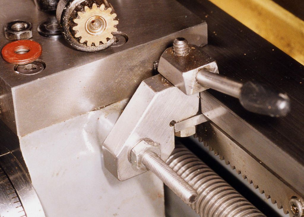
| 86 forum posts 59 photos | First posting and upload of photographs, so I hope this goes ok! Peter: some photos uploaded to an album. Yes, the plate is mounted via the TT attachment holes in the bed. These are actually photos of the first Newall Microsyn installation onto an S7, about which I wrote an article or two which were published in MEW about 2002 - give or take a year! Since then I've found it to be perfectly satisfactory, and I'm about to repeat the installation on another machine. Newall must also think it satisfactory, since they've based their design for their S7 installation kit on it, albeit with the reading head mounted lower, by virtue of it being vertically oriented as opposed to horizontally in my design! KWIL's installation appears to be on similar lines, but with some differences, one of which is worth pointing out. I leave the taper attachment permanently installed - fitting and aligning one of these things is best done only once! The pin on the attachment slide is therefore a permanent feature, but it has to be low enough to allow the crosslide DRO scale to clear it. Which in turn means that to use the attachment it is necessary to make an extension pin that attaches to the original one. My original extension was in the form of a very close fitting sleeve that slipped over the original pin. Inevitably there must be some small clearance and that allows the extension to tip slightly when the saddle moves one way, and tip in the opposite direction when going the other way - which introduces what can best be described as backlash in the taper cutting path. KWIL's unit seems to be mounted somewhat lower than mine, so the tipping/backlash effect will be greater. I suggest that you consider mounting the attachment as high as possible, as per my original drawings in MEW. If you want those drawings I can send them to you direct as .pdf files. Rather than use a sleeve attachment, it's much better to us a clamping system to extend the extension pin - I don't have any photographs of this, but I do have a drawing, so I can send that as well. The pin on this extension arm is a replica of the bit that attaches to the cross slide bracket, so it gives a direct connection between the saddle and the taper turning slide, no backlash there. But even with that it's still advisable to mount the TT attachment as high as possible to minimise twist loadings on the ways and gib of the TT slide. Oh, a very important point here - if you do use a direct, clamped, connection, the TT atachment must be PERFECTLY level with the top of the bed, or the TT attachement will try to push the saddle up or down - which is, I suspect, why the Myford original pin is a sleeve/sliding fit, to allow it to move up and down a bit if the attachment is not in perfect alignment with the shears. If you're not confident about getting this set up spot-on right, stick to the sleeve arrangement, making it a good a fit on the original pin as you can. And mounting the attachment as high as possible, of course! With a low-backlash connection (only the original slide ways and gibs contribute now) setting tapers becomes very easy using the DRO - just zero both axes, then move the saddle one way for say 3", and adjust the TT slide until the cross slide reading shows that you have the required movement to produce the taper. |
| Peter | 27/07/2011 18:47:05 |
3 forum posts | Cabeng
Many thanks your photos are very good.
thanks to you and KWIL the result of my first time posting has exceeded my expectations. I can now see that I can achieve what I want. It will help a lot if you could send me your dwgs in .pf format.
PeterM |
| Cabeng | 27/07/2011 23:20:25 |
| 86 forum posts 59 photos | I can't find a way of doing this at the moment - 'message member' doesn't seem to allow attachments. Not even taper turning attachments! Unless someone can tell me how to do it, I'm going to need your direct e-mail address - I've sent you mine via the 'message member' facility, if you respond via your 'normal' e-mail address I'll send them to you - 2 drawings, A3 size. I hope you've been metricated! |
| Michael O'Connor | 01/01/2015 01:04:40 |
| 16 forum posts 20 photos | Hello, Sorry to drag up an old thread, but it contains posts by two members who I believe can answer my question. Just purchased all of the Newall components to add a DRO to my Myford S7. Researching this forum I found several references to the problem of moving the carriage lock to the front of the saddle. Two photos show what appears to be the right hand counterbored location of the front saddle gib strip being used to lock the saddle. In the Myford factory DRO installation, it appears that they added another SHCS to the left of the original location to hold the front gib strip and shim with the original location being used as a lock. My question is: Did Myford just use the original front gib strip to lock the carriage or did they actually use something similar to the original lock? The original counterbore for the right hand gib strip SHCS is too far from the bed to use that location for a similar to the original design carriage locking device. There appears to be room to the right of this location (end of the front gib strip) to install something. Would love to hear about what others have done to solve the problem. I would like to keep my new carriage lock on the saddle. Please see photo in next post below. Thanks! Regards, Mike Edited By Michael O'Connor on 01/01/2015 01:28:07 |
| Michael O'Connor | 01/01/2015 01:27:07 |
| 16 forum posts 20 photos |
Thanks, Mike
|
| Andrew Moyes 1 | 01/01/2015 11:25:20 |
| 158 forum posts 22 photos | Hello Mike. The photo you posted is of my lathe when it was new and is one I posted to my album when this topic came up before. I have read and re-read you penultimate post and confess I can’t understand it, especially the reference to socket head cap screws securing the gib. The gib on the saddle is not made in the same way as that on the Super 7 cross-slide. The counterbored cap screws are to secure the apron to the saddle, not the gib to the saddle. The gib is rectangular and is free to float, being pushed into contact with the front shear by the three screws in the front of the saddle that have locking nuts. The saddle lock is the hexagon head screw that sticks up above the top of the saddle, with the oil nipple immediately behind it. When Myford fitted the Newall DRO and moved the saddle lock to the front, they used a similar construction of saddle lock. The rear lock has a thick mild steel disc that sits in a counterbore in the underside of the saddle. The disc and counterbore are offset to the screw so that one side of the disc extends under the shear to clamp the saddle when the screw is tightened. In its front incarnation, it’s a rectangular block instead of a disc. The problem is that in the front position, mine just doesn’t work. I have lost count of the number of times that I have moved the saddle with the handwheel, not realising that the lock is still applied – which tells you how ineffective it is. A closer look showed that the screw is too far away from the front shear to apply enough clamping force – the geometry is not good. The reason is that the gib strip must pass between the screw and the front shear, which of course doesn’t apply when the lock is at the back of the saddle. A further thing I don’t like is that there isn’t room to swap the screw for a lever with a decent enough handle without fouling the DRO encoder. It means I have to use a spanner every time and often the screw is hidden from view under the topslide. Very inconvenient for an operation that will be done countless times in the life of the lathe. Making an alternative lock has been on my to-do list for a while. There was a design for an external saddle clamp in MEW 163. I like the idea of using the thread dial indicator stud as a fixing for the clamp but I thought other aspects were a bit Heath Robinson. Another approach would be to drill and tap for a fourth gib adjusting screw and fit a handle so it locks the gib up tight, similar to that on the Myford top slide (and cross-slide of the ML7, not Super 7). The lever would be conveniently on the front of the saddle but it would involve a major strip-down to install. If anyone can think of any other good solution, I would be glad to hear of it. Andrew M Edited By Andrew Moyes 1 on 01/01/2015 11:38:42 |
| Cabeng | 01/01/2015 12:26:31 |
| 86 forum posts 59 photos | I would agree 100% with Andrew re the re-positioned saddle clamp, not vey good, and inconveniently located - it always seems to hide under the cross slide every time I want to use it! But I must disagree 100% with his comments on this one:
I've lived with this for nearly 20 years (I didn't make it, it came fitted to the lathe) and have found it to be very effective and very convenient - a nice solution to a tricky problem, and I can recomend it without hesitation. Here's the original design by Don Ainley, from ME:
I'm currently making one for my Connoisseur, alongside a friend making one for his PCF S7B - unfortunately we've found that the few dimensions given aren't quite right for a PCF machine, the position of the indicator stud seems to have been shifted slightly on green and blue machines compared to grey ones. I should have the right dimensions before too long, but this is a relatively slow process as it's being used as a teaching exercise for my friend, who's new to model engineering, and progress only happens one afternoon a week. And for some reason has completely stopped over the last couple of weeks! |
| Michael O'Connor | 01/01/2015 16:04:58 |
| 16 forum posts 20 photos |
Thank you Andrew for the very detailed and informative response to my post. Your confusion is due to my incorrectly referring to the Saddle Strip (Front) Myford KA7 #A9185 as a "Front Gib Strip". What I was wondering was if your lathe was using the Saddle Strip to lock the carriage. Sorry for the confusion. Thanks for the insight. Thank you Cabeng for documenting your Myford S7 Newall DRO installation in MEW No.87 (Dec.2002/ Jan.2003) and for your response to my carriage lock question. It looks like an external lock may be the best solution. Kind regards, Mike
|
| Andrew Moyes 1 | 01/01/2015 18:29:02 |
| 158 forum posts 22 photos | Thanks Cabeng for the drawing of the Don Ainley lock. To my eyes, that's more elegant than the version I referred to in MEW163. I'll go with your recommendation and will move it up my to-do list! Mike - thanks for your explanation. I see where you were coming from now. Andrew M
|
| Cabeng | 02/01/2015 00:17:02 |
| 86 forum posts 59 photos | I see that I made an invalid assumption that it was the Ainley design to which you were referring - Wrong again! So my apologies for disagreeing with you Andrew! |
| Cabeng | 21/06/2015 01:08:40 |
| 86 forum posts 59 photos | Some time ago (see above) I posted re. a saddle clamp designed in 1992 by Don Ainley, and said that I would provide drawings when I’d finished manufacturing one for my lathe. Colin Rawson has reminded me that I’ve forgotten about this promise (thank you Colin!), so I’ve now put the drawing in an album, along with a copy of Don Ainsley’s original M.E. submission and a couple of photographs. Here’s the drawing:
A mixture of imperial & metric units - I normally work in metric, but the measurements of the mounting stud position were taken using imperial measuring equipment! Anyone intending to make one of these clamps should note the note about dimensions and surfaces shown in red, and the panel top left of the drawing showing relevant measurements taken from my S7 & Connoisseur machines – it would appear that all Myfords are not created equal, and these dimensions do affect the performance of the clamp. It has been tried on grey, green & blue machines and works on all of them, but clamping is noticeably better on the blue one, for which it was made. The effect of variations in the Myford dimensions can be seen here:
The gap between the clamp and the front of the shear is greater on the grey one, the top lip isn't perfectly flat on the bed, and the clamp plate is more horizontal – so as the note on the drawing says, you should adjust the red dimensions to suit your machine. To find the position of the mounting stud relative to the front of the bed a 1” parallel was clamped to the bed, distances between the parallel and the stud were then determined using slip gauges for the vertical position and a feeler gauges for the horizontal distance:
Apart from the 'red' items, none of the other dimensions are critical, so I haven't shown them, those that are shown are for information, and do not need to be slavishly followed!
|
| Martin King 2 | 07/04/2016 16:39:42 |
 1129 forum posts 1 photos | Hi Cabeng, do you have the issue number please for the saddle lock article? Regards, Martin |


Please login to post a reply.
Magazine Locator
Want the latest issue of Model Engineer or Model Engineers' Workshop? Use our magazine locator links to find your nearest stockist!
Sign up to our Newsletter
Sign up to our newsletter and get a free digital issue.
You can unsubscribe at anytime. View our privacy policy at www.mortons.co.uk/privacy
Latest Forum Posts
- *Oct 2023: FORUM MIGRATION TIMELINE*
05/10/2023 07:57:11 - Making ER11 collet chuck
05/10/2023 07:56:24 - What did you do today? 2023
05/10/2023 07:25:01 - Orrery
05/10/2023 06:00:41 - Wera hand-tools
05/10/2023 05:47:07 - New member
05/10/2023 04:40:11 - Problems with external pot on at1 vfd
05/10/2023 00:06:32 - Drain plug
04/10/2023 23:36:17 - digi phase converter for 10 machines.....
04/10/2023 23:13:48 - Winter Storage Of Locomotives
04/10/2023 21:02:11 - More Latest Posts...
- View All Topics
Support Our Partners


Shopping Partners
Subscription Offer

Latest "For Sale" Ads
- Reeves** - Rebuilt Royal Scot by Martin Evans
by John Broughton
£300.00 - BRITANNIA 5" GAUGE James Perrier
by Jon Seabright 1
£2,500.00 - Drill Grinder - for restoration
by Nigel Graham 2
£0.00 - WARCO WM18 MILLING MACHINE
by Alex Chudley
£1,200.00 - MYFORD SUPER 7 LATHE
by Alex Chudley
£2,000.00 - More "For Sale" Ads...
Latest "Wanted" Ads
- D1-3 backplate
by Michael Horley
Price Not Specified - fixed steady for a Colchester bantam mark1 800
by George Jervis
Price Not Specified - lbsc pansy
by JACK SIDEBOTHAM
Price Not Specified - Pratt Burnerd multifit chuck key.
by Tim Riome
Price Not Specified - BANDSAW BLADE WELDER
by HUGH
Price Not Specified - More "Wanted" Ads...
Get In Touch!
Do you want to contact the Model Engineer and Model Engineers' Workshop team?
You can contact us by phone, mail or email about the magazines including becoming a contributor, submitting reader's letters or making queries about articles. You can also get in touch about this website, advertising or other general issues.
Click THIS LINK for full contact details.
For subscription issues please see THIS LINK.
Digital Back Issues


Donate

 Register
 Log-in
Model Engineer Magazine
- Percival Marshall
- M.E. History
- LittleLEC
- M.E. Clock

ME Workshop
- An Adcock
- & Shipley
- Horizontal
- Mill

Subscribe Now
- Great savings
- Delivered to your door

Pre-order your copy!
- Delivered to your doorstep!
- Free UK delivery!
All Forum Topics > Hints And Tips for model engineers > S7 Newall DRO v Taper Turning attachment