Forum sponsored by:

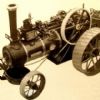
Allchin 11/2" scale
Building problems
| Bernard Laycock | 16/05/2011 16:00:12 |
| 10 forum posts | I am becoming more and more depressed at the problems I have encountered trying to build Hughe's 11/2" Royal Chester Allchin traction engine. A combination of errors on the drawings and in the book plus my own lack of experience have culminated in today's experience when I began to plan for the construction of the water pump. The details on drg 11 are fine as far as they go, but I notice there seems to be no detailed dimensions of the eccentric rod.
Never mind I told myself, perhaps all will be revealed in the book - but a comprehensive search of the index and the relevant chapter has revealed that there is no mention whatsoever of this component in the book.and I am therefore completely stymied unless someone with a great deal more expertise than I possess and who has already built the machine will be able to help me to find instructions. There must be hundreds of builders who have managed this and I hope at least one will take pity on me. |
| JasonB | 16/05/2011 16:14:09 |
 25215 forum posts 3105 photos 1 articles | Its one of those components that really needs making top fit teh job.
The basic shape is shown on dwg 11 as well as the offset and thickness of material. I would cut a card template to see what fits and make sure nothing catches as the crank is turned. Then make it from metal a little overlength at the pump end, the pin hole can be marked on assembly and any excess trimmed off.
Jason |
| mgj | 16/05/2011 16:21:18 |
| 1017 forum posts 14 photos | Chin up Bernard- you don't have a problem. You know the distance from the centre of the crank to the end of the pump. So now you can take off that, the length of the ram forward of its pivot. Now you take off that 1/2 the travel of the ram = the eccentric offset. (I imagine both eccentric and ram are dimensioned) Knock up a rod to fit . First time you try it out, you may have to shave a bit off the nose of the pump ram, if it fouls. Or you can give it .010" clearance from the outset. Either way will work, which is what matters. If you can't get those dimensions now, then fret not. Just wait till you have enough of the engine erected and you can . Actually that is a better way of doing it than making it precisely to drawing - you want the minimum clearance volume in that pump so it can clear airlocks - so you were going to do it that way anyway???? These things are not that critcal. The originals were made with blacksmith technology, and at your worst you will do better than that! Good luck. |
| JasonB | 16/05/2011 17:28:20 |
25215 forum posts 3105 photos 1 articles | MGJ, its not just a straight rod so you can't easily work out the distance. It has a curved shape as the horizontal ram is about 1" below the ctr of the eccentric, it has to pass under the spec plate & 2nd shaft and it is also jogged to one side. This is why I said make a card template and adjust to clear all teh other parts.
J Edited By JasonB on 16/05/2011 17:29:42 |
| mgj | 16/05/2011 18:51:28 |
| 1017 forum posts 14 photos | Jason our posts actually crossed. I can see the difficulty - you post wasn't up when I replied, so please don't think I was cutting across you, and your knowledge is greater than mine..
We have to accept dodgy drawings - so one is never knackered till the fat lady sings as it were.If you don't have dimensions, somehow you have to find them, by whatever means? Or cut and shut till it does work.
No one is completely stymied! Edited By mgj on 16/05/2011 18:52:25 |
| Jeff Dayman | 16/05/2011 19:08:59 |
| 2356 forum posts 47 photos | A bent piece of heavy steel wire, .06 to .09" , like that found in coat hangers, is often very handy for figuring linkages on the job where space is close. Card works great, but sometimes the wire is better especially if there is an offset involved. If you grind the end flat, it can touch the pump ram pin when it is all the way into the pump. bend the wire to clear the nearby stuff, and so it sits on the side of the eccentric. Then scribe the wire where the eccentric face ends (with eccentric throw at position of pump max stroke). You now have a close measure of the max linkage length between pin and eccentric. You now need to add half the ram pin dia and half the eccentric diameter to the wire length marked out, to get the link centre to centre dimension, and also subtract a shade for ram end clearance too, from the calculated centre dimension.
The centre to centre distance can then be marked out on a link blank, and the wire used to mark out the profile in side to side and up and down dimensions. You can do a quick machined / sawn mockup in soft scrap aluminum to be sure everything fits, before doing the final one in steel or cast iron.
Hope these ideas help, Bernard.
JD |
| AlasdairM | 20/05/2011 08:26:44 |
| 11 forum posts | Hi Bernard - althought not a direct answer to your query, the following is a link to another thread on the Allchin water pump on this forum - if not of interest to you, simply ignore it!
Good luck, A |
| Bob Newman | 29/06/2011 20:48:28 |
 1 forum posts 3 photos | Bernard, I too am building the Allchin in 3". I think you are further advanced than me though but I have a friend who has also built the Allchin (by the way he is a Gold medal winnwer which will give you an ide of the quality of his work). If your problem has not been solved yet I would be happy to ask on your behalf, let me know. You may also like to know that the pump lever is prone to snap because of it's angle and shape. I will try and upload a picture of a mod I came accross to support the arm. Good Luck, Bob Edited By Bob Newman on 29/06/2011 21:09:52 |
| Bernard Laycock | 23/08/2011 16:04:31 |
| 10 forum posts | Thanks guys, I'm very grateful for your help and encouragement. Bernard |
| Stephen Spice | 03/01/2012 19:23:31 |
| 21 forum posts 52 photos | I sympathise with Bernard regarding the water pump as I am about to fit this item.
But having got everything ready to fit. I find that I can't place the pump on the bearing bracket platform without it fouling the side hornplate.
Iv'e checked all the dimentions on both pump and bearing being ok. I now have to decide wether to silver solder an extention to the pump bottom about 1/8"or take a notch out of the hornplate. Either way might add to the problem of fitting the rod crank.
So I might just wait a while to see if any of you chaps have come accross this same problem.
Could we also discuss setting the valve slide?
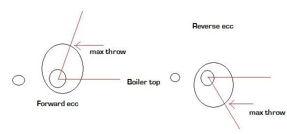
When I came to W.J. Hughes page 195 this was going to be so easy. But having made up a nice metal template to the 821/2 deg. Not being at all familiar with this subject I was then at a loss as to wether to line this up to the centre line on the centre eccentric pieces or to the forward shells having removed the rears to expose the adjusting srews.
I assumed that the template was to be placed on the boiler top but there was no mention as to wether it should be placed forward or to the rear of the crank shaft.
I couln't help noticing that on sheet six refered to there is nothing that matches the 821/2.
I realise that one shouln't try to "scale" drawings but after trying to set the valve over several days I was becoming a bit desperate.
I finally contacted a very experienced model builder who had also built the Allchin and was advised to adjust this by trial and error and I think that I may have actually cracked it. but very annoyed that I wasn't able to do it in the propper way. It's as though I could'nt see the wood for the trees and missed something entirely.
Any comments about this would be much appreciated.
Thanks Jim. |
| JasonB | 03/01/2012 19:38:35 |
25215 forum posts 3105 photos 1 articles | If you look at the "arrangement of valve gear" top right of sheet six and draw an imaginary line through the centre of the crank shaft at the same angle shown on the template that will pass throght the point of maximim throw on the eccentric eg the max throw of the eccentric should be at about 1 o'clock when the crank is fully forward and the max of the reverse eccentric at about 5 o'clock.
J
Edited By JasonB on 03/01/2012 20:02:57 |
| JasonB | 03/01/2012 20:13:40 |
25215 forum posts 3105 photos 1 articles | This should help
 J |
| Ady1 | 03/01/2012 20:16:21 |
 6137 forum posts 893 photos |  At a recent exhibition I watched a fellow visitor purchase the book and took the opportunity to mention what a task he was letting himself in for......I am sure that he didn't believe me when I said the I had spent 6 years on my model...he might not take that long, but it may well take him two or three years, depending on his other commitments. Edited By Ady1 on 03/01/2012 20:17:43 |
| Stephen Spice | 04/01/2012 18:41:03 |
| 21 forum posts 52 photos | That was quick JasonB. Many thanks for your advice and I think I might have got somewhere near it so I will pump her up on compressed air later on and keep your drawing to back me up. Kind regards Jim. |
| Stephen Spice | 11/02/2012 18:39:57 |
| 21 forum posts 52 photos | With regard to the water pump. I'm sure that we all have more of a problem with some parts than others.
I didn't find this too bad myself and managed to make and fit the accentric rod without resorting to any aditional templates.
I made the rod as near as possible to the drawing leaving it a bit longer,and with just the crankshaft and pump accentric in position and the pump body on the platform. with the pump piston 1/32 back from forward stroke. I gradually assesed the length that would be about right. Put the bend in which was very small.And I then marked where the rod and accentric came together. Removed and swetted them together with solder paste so that nothing would be spoiled if it was wrong.
Of course I had to cut a notch in the front plate to clear the rod and I think that was the most tedius job about 1/8 in my case.
The only real problem that I had was that it rubbed the crank on the crankshaf and had to put a better rounded corner on that.
As I seem to have got it right I think i'll leave it soldered and just put the srews in and leave it at that. Jim. |
Please login to post a reply.
Magazine Locator
Want the latest issue of Model Engineer or Model Engineers' Workshop? Use our magazine locator links to find your nearest stockist!
Sign up to our Newsletter
Sign up to our newsletter and get a free digital issue.
You can unsubscribe at anytime. View our privacy policy at www.mortons.co.uk/privacy
Latest Forum Posts
- hemingway ball turner
04/07/2025 14:40:26 - *Oct 2023: FORUM MIGRATION TIMELINE*
05/10/2023 07:57:11 - Making ER11 collet chuck
05/10/2023 07:56:24 - What did you do today? 2023
05/10/2023 07:25:01 - Orrery
05/10/2023 06:00:41 - Wera hand-tools
05/10/2023 05:47:07 - New member
05/10/2023 04:40:11 - Problems with external pot on at1 vfd
05/10/2023 00:06:32 - Drain plug
04/10/2023 23:36:17 - digi phase converter for 10 machines.....
04/10/2023 23:13:48 - More Latest Posts...
- View All Topics
Support Our Partners


Shopping Partners
Subscription Offer

Latest "For Sale" Ads
- Reeves** - Rebuilt Royal Scot by Martin Evans
by John Broughton
£300.00 - BRITANNIA 5" GAUGE James Perrier
by Jon Seabright 1
£2,500.00 - Drill Grinder - for restoration
by Nigel Graham 2
£0.00 - WARCO WM18 MILLING MACHINE
by Alex Chudley
£1,200.00 - MYFORD SUPER 7 LATHE
by Alex Chudley
£2,000.00 - More "For Sale" Ads...
Latest "Wanted" Ads
- D1-3 backplate
by Michael Horley
Price Not Specified - fixed steady for a Colchester bantam mark1 800
by George Jervis
Price Not Specified - lbsc pansy
by JACK SIDEBOTHAM
Price Not Specified - Pratt Burnerd multifit chuck key.
by Tim Riome
Price Not Specified - BANDSAW BLADE WELDER
by HUGH
Price Not Specified - More "Wanted" Ads...
Get In Touch!
Do you want to contact the Model Engineer and Model Engineers' Workshop team?
You can contact us by phone, mail or email about the magazines including becoming a contributor, submitting reader's letters or making queries about articles. You can also get in touch about this website, advertising or other general issues.
Click THIS LINK for full contact details.
For subscription issues please see THIS LINK.
Digital Back Issues


Donate

 Register
 Log-in
Model Engineer Magazine
- Percival Marshall
- M.E. History
- LittleLEC
- M.E. Clock

ME Workshop
- An Adcock
- & Shipley
- Horizontal
- Mill

Subscribe Now
- Great savings
- Delivered to your door

Pre-order your copy!
- Delivered to your doorstep!
- Free UK delivery!
All Forum Topics > Traction engines > Allchin 11/2" scale