Forum sponsored by:

Dovetails
| Peter Simpson 2 | 20/04/2011 07:59:11 |
| 28 forum posts 1 photos | Hi Guy's
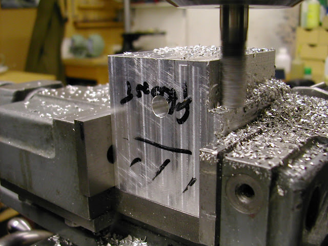
I'm in the middle of making a boring head for my milling machine. I have cut the female half of the dovetail which turned out very well after an initial cutter jam. After the jam I increased the cutter speed and nipped up the cross slide gib strip to reduce any back lash. I took cuts of about .5mm which seemed to be the maximum the machine could handle ( Tom Senior Light Vertical). During the cutting the cutter appeared to make dust rather than normal milling cuttings. Is there anything I'm missing prior to cutting the male half of the dovetail. Many thanks for any advice given |
| Ramon Wilson | 20/04/2011 08:33:24 |
 1655 forum posts 617 photos | Hi Peter, I wouldn't worry too much about the swarf as usually the cutters are multifluted and tend to create that situation. You don't state the material but I'm assuming steel.
I would however be more concerned by the fact that you need to tighten the gibstrip to 'eliminate the back lash'. That to me sounds like you were possibly 'upcutting' ie the edge being cut was moving with the cutter rotation. That would certainly explain any grabbing of the cutter and potential jamming. I would however 'finish' the final cut by upcutting as normally this produces a better finish but the cut should only be taking a whisker off
The .5 depth of cut may not seem great but the length of it is so may be back off a little on depth. DT cutters are cutting over their length at varying cutting speeds and don't act quite like a normal cutter. It may help to take out the major area for removal in steps before finishing with the full face length. It won't hurt either to slow things down a bit on speed and feed from what you would expect from a conventional mill of similar size.
Hope this helps
Regards - Ramon |
| Ramon Wilson | 20/04/2011 18:53:23 |
1655 forum posts 617 photos | That's a neat technique Gray, I've not seen that before.
It's been a while since cutting dovetails and had overlooked the cutting on the bottom of the cutter at the same time as the side. I have always cut the bottom first (after most of the dovetail has been removed) then lift the cutter slightly to achieve the same conditions for the side of the cutter. Does the same thing but your idea looks much neater - always assuming you have a '45' at your disposal too.
I also assumed Peter had removed the centre of the female half using a conventional mill hence my thoughts on climb milling. Again I would (have) - if design allowed - remove the centre portion a fraction lower than the dovetail face to give the cutter the minimum 'face' work to do.
Let us know how you get on Peter
Regards - Ramon
|
| Peter Simpson 2 | 20/04/2011 19:15:28 |
| 28 forum posts 1 photos | Many thanks for the replies, just to give you more of an overview on the job. The material is EN3 and the centre section of the dovetail had been removed using a normal end mill. The cutter was certainly not cutting on both sides but was skimming the bottom face. The cut was been taken along with direction of cutter rotation. Chears guy's |
| John Olsen | 20/04/2011 20:05:06 |
| 1294 forum posts 108 photos 1 articles | I always cut my dovetails on a shaper, no expensive cutters and a finish that vertical mills can only dream about. regards John |
| Ramon Wilson | 21/04/2011 00:19:13 |
1655 forum posts 617 photos | Oh dear, Anyone notice I got my 'up cutting' mixed up from my 'down cutting' in
the first post!
 I knew what I meant - climb milling. Another freudian slip? or just being chivvied by the general. Whatever, it sounds like that was the cause of Peters jam
Ramon |
| James B | 21/04/2011 09:20:43 |
 101 forum posts 14 photos | Hi Ramon,
I was interested to read that you suggest a fine finishing cut by climb milling to get a better finish - or have I misunderstood? I have always avoided climb milling where possible...
I'm with John on the shaper - still learning on my shaper, but very versatile, and a great finish. Nice to watch too!
James |
| John Olsen | 21/04/2011 09:54:03 |
| 1294 forum posts 108 photos 1 articles | Using a shaper is not cheating, it is the proper way to do it. Well, a planer might be even more proper, but finding one that will fit in the amateurs workshop is getting to be a bit of a mission. Have you ever had a professional machinist mistake your work for something off a surface grinder? When it was actually done on a fifty year old shaper with a HSS toolbit? So what sort of shaper do you have James? regards John |
| Ramon Wilson | 21/04/2011 11:11:19 |
1655 forum posts 617 photos | Hi James,
Given conventional machinery ie fitted with normal leadscrews and nuts climb milling should,as you say be avoided. I'm sure you are only too aware that this is because the tool will pull the work into the cutter over the length of any backlash in the leadscrew and nut combination. However climb milling will produce a better finish generally so on final cuts where the depth of cut is minimal the cutting forces are not enough to overide the back lash.
On my small mill with the gibs well adjusted I can get away with a reasonable cut particularly in ally though I was recently doing it when machining the crankshafts for the ETA engines - EN24t - though the cuts were minimal the reduction in cutting forces that climb milling give made the task that much easier but it will catch you out if you push it too hard. My mill does have a spring loaded nut on the x-y leadscrew though which helps.
I am not advocating it - just saying it does help at times - strangely enough the one area where I find it most useful is on rotary table work - providing the cut is not too big the effort to continuously turn the handle is definitely lower.
Most of my work is quite small I should add so perhaps that's why I can get away with but on that last two thou finishing cut it on most parts shouldn't cause any problems.
Regards - Ramon
|
| Ramon Wilson | 21/04/2011 13:33:54 |
1655 forum posts 617 photos | Hi Gray,
My limited experience with CNC quickly lead me into regular climb milling. The machine at my disposal, a Haas VF4, could certainly shift some metal at what seemed (after conventional machining) simply alarming rates but I hasten to add compared to what I saw on occasion at exhibitions we were only playing at it
 One job we did, a bearing housing for a small press, previously done on the Colchester went from near 4hrs to 11mins drilled and counterbored too. I came to it much too late in life to really get into it but that said I wouldn't have missed my time with 'convention' for anything.
Ah happy days.
Ramon |
| James B | 21/04/2011 21:02:59 |
101 forum posts 14 photos | Hi John I have an Elliot 10M - not a huge machine, but big enough for me - doesn't take up too much shape in the workshop. As I say, still learning, but the fact you can use HSS tools to get a good finish is ideal. One thing I want to get to grips with is keyway cutting, and have also an old ME article showing a worm and wheel setup on the tool post to allow you to cut radius surfaces - i.e. chimney bases, etc. What do you have? James |
| James B | 21/04/2011 21:15:33 |
101 forum posts 14 photos | Hi Ramon, Thanks for that - I think some experimenting is called for! My mill is a larger older machine, so rigidity is not a problem, but have some backlash in the feedscrews to work with. I will get some bits from the scrap box and and have a play and compare finishing cut methods. Would this just apply to dovetals, or 'normal' milling as well? Also, just to let you know, your diesel engines posted here recently have inspired me to get started on my first IC engine - have chosen a Sparey 5cc diesel! Thanks, James |
| Ramon Wilson | 21/04/2011 22:49:39 |
1655 forum posts 617 photos | HI James,
Yes try it and see - like for like on depth of cut - which as said needs to be small (relative to the machine and size of cutter) you will notice a definite difference in finish and the effort if you are using hand power. Under power feed keep the feed rate low.
It goes for all usual helical cutters not just dovetails. This pic from the Racer file shows a rippa cutter climb milling on the crankcase. 10mm cutter radial cut about 2mm depth about 12 I would say. Another slight advantage on ally is that the cutter has less tendency to load up particularly when you have no coolant system to call on
 I must stress again I am not advocating this as the way to go - it is very easy to 'catch a crab' very quickly indeed even if you are ready for it so tread carefully.
Good luck with the engine - I haven't made one but many successful ones have been done over the years - you have chosen a good one to start with
Regards - Ramon |
| John Olsen | 22/04/2011 01:53:09 |
| 1294 forum posts 108 photos 1 articles | OK, well first a little lesso I just taught myself about climb milling. I am making a couple of bow fairleads for my steam launch. These set into the top edge of a board taht meets the stem piece at a shallow angle, and have what amounts to a T slot cut in them at the same shallow angle. A rope passing over the bows can be dropped into the T slot so that it tends to stay there and doesn't wear any wood. So, to make the slot I took out the vertical part of the T with a slot drill, then machined the horizontal part with a large Woodruffe cutter, almost two inches in diameter.With the job being at an acute angle to the direction of travel, it is inevitable that the cutter is going to be climb milling for part of the cut., entering for one hand of fairlead and exiting for the other. All went well on the first one. On the second one, with my wife watching, it started OK, but after a short amount of cutting suddenly complained, made a loud bang, and the cutter stopped turning. The problem was that the screw thread on the cutter had broken up inside the chuck. Since the rest of it was fine, I splashed out and bought myself an ER32 collett chuck set, which I had been wanting anyway. A bit of thought told me that I had done the first one with the cutter going quite a lot faster, and this was a quite machineable bronze which seem happy to be machine at quite good speeds, so I upped the speed to four times as fast, slowed the table feed down a bit an had another go. It went through just as nicely as the first one had. So my lesson from this is that when you are climb milling, don't have the cutter going to slow. The machine incidently is one of the bigger mill drills, quite solid but with no special precautions against backlash. On the shapers, well, I have four of them...Ammco 6", Alba 10", 14" and 18". Ok, I know this is excessive and I should get a life. I've never had the 14" one going yet, it has all the gear for a flat belt drive with fast and loose pullies. The others all go although the Ammco could use a bit of work on the non original fine feed. regards John |
| Ramon Wilson | 22/04/2011 09:50:28 |
1655 forum posts 617 photos | Hi John, Now that's exactly what I mean about a 'catching a crab'
 Upping the speed? well that will give more teeth past in a given time which eases the forces per tooth but you could exceed the cutting speed of the material though in bronze the last thing needed is to slow things down too much and then work harden it through rubbing. Like so much else it's a 'balance thing'
It's a good lesson though, and serves to show that climb milling is not the way to go about milling (conventional as opposed to CNC) generally.
Regards - Ramon |
| John Olsen | 22/04/2011 22:57:02 |
| 1294 forum posts 108 photos 1 articles | One of the things to look for in purchasing a shaper is to check for evidence of a crash. Apart from missing teeth on the bull wheel, there can be damage to the slotted arm. My little Ammco has had the arm brazed back together at some point, fortunately they had made a very good job of it so it runs fine. The 18" Alba had had a more minor mishap that took one corner off the downfeed dovetail, on the side with the gib strip and screws. So I was able to clean up the corner and replace the missing chunk of metal and the missing screw for the gib. Still, when you manage to buy a machine that size complete with the original 10" vice for NZD 350 (say under 200 pounds) you can't complain. Hi Ramon, yes, my reasoning was that at the higher speed I was still under the maximum cutting speed, while the tooth load would be greatly reduced, reducing the tendency to grab the job and take up the backlash. I have since realised that the angle means that I did not need to use a T slot cutter at all, I could have done the job from the side with a slot drill...which I did in the end with a ball ended cutter to round the bottom of the T slots. Oh well, I got there and they will look pretty good in place, once I finish rounding them off and polishing them. I have a part built Sparey here...currently waiting for me to figure out how to machine the various holes through the cylinder wall and then braze on the transfer and inlet port bits without totally spoiling the whole thing. I suppose I can run a little hone through the bore afterwards, but will it still be round? regards John |
| Ramon Wilson | 23/04/2011 14:48:57 |
1655 forum posts 617 photos | Hi John, 'Getting there' is the main thing, the path trod does is not always that important.
Re the Sparey, should you ever have the time from your magnificent task in hand then I would use a low melting point silver solder for the venturi bush and use ordinary soft solder for the transfer cover. Try and use a general heat rather than a localised one for the SS letting it cool naturally. A brake cylinder type hone won't take out any distortion but a lap will so relap and then make the piston to fit.
You may -probaly will - find theres very little distortion anyway but I would still relap. If you have already made the piston and it is then to loose you can, providing its cast iron, 'grow it' by heating to cherry red and quenching. This probably will distort it slightly but normally it will grow enough to allow relapping before lapping to the bore. I have reclaimed several well worn diesel engines using this method. You can only do it once per piston though
I was hoping to get on with the liners and pistons for the Etas this week but I have been respectively reminded that we are on holiday - don't ya jest luv 'em
Regards - Ramon |
| John Olsen | 24/04/2011 06:31:04 |
| 1294 forum posts 108 photos 1 articles | Hi Ramon, No, I haven't made the piston yet so I guess I have room to manouvre. These sort of projects tend to happen in moments when one gets too tired of sanding. Ah well, one side of the boat now has its final coat of paint on, now I have to give it long enough to harden, then lay her over and do the other side. regards John |
| jomac | 25/04/2011 13:36:31 |
| 113 forum posts | Ramon Hi, Im'e starting a new motor, which has a 11mm bore, Iv'e got two options with the cylinder /piston, I have a 20mmx900mm length of groung chrome moly bar, and a short length of 20mm round good cast iron, because I tend to get over enthusiastic when turning I think I will make the cylinder from the chrome-moly and cut off a small section of the cast iron for the piston. I am just a bit worried about drilling the transfer ports, there is two on either side 2.5mmR spaced 1.7mm apart, and in the original drawings the two exhausts are cut with a 30mm saw,(dont have one) so will cut the exhaust with a 2.5mm slot drill, NOW what I was thinking, cut the cylinder over long face the ends center drill the center and use a sharp tool to scribe a line 11mm diameter. OK done that.!!! mounted the blank on the rotary table (I made steel tee slot clamps with adjustable ally jaws) DTI to center blank, So far so good, I intend to drill down about 10mm then use a carbide slot mill to finish. NOTE I have not bored out the cylinder yet, cause if I do, then try to mill the slots I think there will be to much movement of the 2.5mm slot/end mill. How would you do it??? or am I on right track. By the way I was going to send another post to the TD article by Terryd, cause the IC engine drawing are 1.32 under size, I tried to enlarge the end view of the cylider using one of three Cad programs, but have forgotten most of the key strokes. went into the work shop, finished it in 6 minutes now scaled up 10 times, I can now see what I am measuring with more accuracy. Sorry about being long winded, but that me. John Holloway |
| Ramon Wilson | 25/04/2011 14:30:59 |
1655 forum posts 617 photos | Hi John, I've just come in from the garden for a break from digging footings and mixing concrete so this is all the excuse I need for a short escape
Whilst it is going off topic somewhat I think Peter's original post has been well answered so I'm sure it won't hurt to deviate a little.
What you describe appears to me to be a viable approach however I feel you may be worrying a little too much about the cutter deflecting.
Personally however I would bore the blank first to a couple of thou under lapping size max. Turn the OD for it's entire length to its maximum diameter - probably that over the exhaust area? - then hold as you describe. I would set a depth stop for the slot drill and then plunge down in small cuts - about .5mm a time - moving the cutter outwards each pass until the 2.5 depth is reached. The cutter should cope with this without deflecting even in your alloy steel. Mount the liner on a expanding mandrel to finish off all the outer diameters before lapping. This way everything is machined accurately to the bore and not the other way round - a much easier approach.
I'm assuming that as the original calls for a 30mm 'saw' then the exhaust ports are cut radially. Using a 2.5 slot drill will do just as well but I would definitely use a smaller cutter first to ensure the top of the exhaust port is true to print other wise the timing could suffer. On the other hand making a cutter from silver steel is viable even for alloy steel but ensure it is well backed off, harden but don't temper it and keep the rotational speed well down. One of the liners I made for the Racers was from a tough steel and did cause problems hence this advice. Once well backed off the cutter handled the toughness easilly.
All that having been said if the engine is for 'fun use' as opposed to serious flying use then I would consider using a leaded steel liner. This is what I will be using in the Etas but I would prefer to wait until I'm doing them to explain the reasons on that specific thread. I can assure you though that from what I have uncovered a cast iron piston running in a leaded steel liner come highly recommended from a variety of sources and is a very good combination for 'sport use'. It has been used in high performance engines too and in one particular instance in a very high tech, 2.5cc racing engine but more on that later.
Hope this helps John - BTW what's the engine? One from MEN's plans book?
Regards - Ramon
|
Please login to post a reply.
Magazine Locator
Want the latest issue of Model Engineer or Model Engineers' Workshop? Use our magazine locator links to find your nearest stockist!
Sign up to our Newsletter
Sign up to our newsletter and get a free digital issue.
You can unsubscribe at anytime. View our privacy policy at www.mortons.co.uk/privacy
Latest Forum Posts
- hemingway ball turner
04/07/2025 14:40:26 - *Oct 2023: FORUM MIGRATION TIMELINE*
05/10/2023 07:57:11 - Making ER11 collet chuck
05/10/2023 07:56:24 - What did you do today? 2023
05/10/2023 07:25:01 - Orrery
05/10/2023 06:00:41 - Wera hand-tools
05/10/2023 05:47:07 - New member
05/10/2023 04:40:11 - Problems with external pot on at1 vfd
05/10/2023 00:06:32 - Drain plug
04/10/2023 23:36:17 - digi phase converter for 10 machines.....
04/10/2023 23:13:48 - More Latest Posts...
- View All Topics
Support Our Partners


Shopping Partners
Subscription Offer

Latest "For Sale" Ads
- Reeves** - Rebuilt Royal Scot by Martin Evans
by John Broughton
£300.00 - BRITANNIA 5" GAUGE James Perrier
by Jon Seabright 1
£2,500.00 - Drill Grinder - for restoration
by Nigel Graham 2
£0.00 - WARCO WM18 MILLING MACHINE
by Alex Chudley
£1,200.00 - MYFORD SUPER 7 LATHE
by Alex Chudley
£2,000.00 - More "For Sale" Ads...
Latest "Wanted" Ads
- D1-3 backplate
by Michael Horley
Price Not Specified - fixed steady for a Colchester bantam mark1 800
by George Jervis
Price Not Specified - lbsc pansy
by JACK SIDEBOTHAM
Price Not Specified - Pratt Burnerd multifit chuck key.
by Tim Riome
Price Not Specified - BANDSAW BLADE WELDER
by HUGH
Price Not Specified - More "Wanted" Ads...
Get In Touch!
Do you want to contact the Model Engineer and Model Engineers' Workshop team?
You can contact us by phone, mail or email about the magazines including becoming a contributor, submitting reader's letters or making queries about articles. You can also get in touch about this website, advertising or other general issues.
Click THIS LINK for full contact details.
For subscription issues please see THIS LINK.
Digital Back Issues


Donate

 Register
 Log-in
Model Engineer Magazine
- Percival Marshall
- M.E. History
- LittleLEC
- M.E. Clock

ME Workshop
- An Adcock
- & Shipley
- Horizontal
- Mill

Subscribe Now
- Great savings
- Delivered to your door

Pre-order your copy!
- Delivered to your doorstep!
- Free UK delivery!
All Forum Topics > Beginners questions > Dovetails