Forum sponsored by:

Rotary Table / milling machine
What would I use one for
| Colin Jacobs 1 | 01/03/2011 19:04:16 |
| 69 forum posts 2 photos | What would I use a rotary table for please? Also what are the benefits of using a milling machine? MTA |
| mgj | 01/03/2011 19:55:03 |
| 1017 forum posts 14 photos | Well a lathe generates solids of revolution. Anything where the work turns - cylinders and their derivatives. A mill generates straight lines - the cutter rotates and the job moves in straight lines - so slots grooves etc.(and it can be a drill - plunge cutting.) They can also generate flat or nearly flat surfaces as well Having said that, if you have the right attachment you can convert your lathe into a mill - won't be as rigid nor as flexible but in smaller sizes of task it will get the job done. A rotary table goes on a milling table, and allows the work to be rotated under control, normally of a worm and wheel. Cutting radial slots and parts of a circle. Depending on the table, there are also adaptors which allow gears to be cut, or specific numbers of holes to be drilled, usually but not always equally spaced. Rotary tables will normally be graduated in degrees (and division thereof) of arc. A close relative of the dividing head, which is for cutting gears and multiple spaces/holes, but can also double as a very useful workholding tool.. Edited By mgj on 01/03/2011 19:55:47 |
| Steve Garnett | 01/03/2011 20:46:57 |
| 837 forum posts 27 photos | Another benefit of using a vertical milling machine is the relative ease with which you can drill series of holes in straight lines - or if you have one with a digital readout (DRO), holes in a complex arrangement as well. This is also perfectly possible without the DRO, but it really does make it a lot easier. So a milling machine can also double up as a very posh pedestal drill... And as I hinted above, milling machines do come in two basic varieties - horizontal and vertical. Most people regard vertical milling machines as being generally more useful, and they are generally easier to set up, but horizontal machines also have their uses. Some machines are regarded as 'universal' - they can run as either. |
| Andrew Johnston | 01/03/2011 21:52:32 |
 7061 forum posts 719 photos | A few random thoughts: I would concur with Steve about the use of a vertical mill, with a DRO, as a drilling machine. I hardly ever use my drilling machine; using the vertical mill is just so much more convenient and accurate. And it makes drilling bolt patterns a breeze with the DRO. No more spotting through to one component from another; just drill the two patterns separately and they should fit together. Generally the horizontal mill is seen as a production machine tool, and is less flexible than a vertical mill. However, for a given size a horizontal mill will most likely be heavier, more rigid and more powerful than a vertical mill. So, if you need to move a lot of metal a horizontal mill will do the job much faster. By the way, a universal mill is not one that has both vertical and horizontal capability. It specifically refers to a horizontal mill that has a swivelling table so that, with the aid of a suitable dividing head, it can be used to machine spiral features, such as flutes on a custom cutter, or a helical gear. Regards, Andrew |
| mgj | 01/03/2011 22:42:17 |
| 1017 forum posts 14 photos | Agreed totally about the advantages of a DRO - but in his other post colin does say he's a beginner. Milling DROs offer a number of useful functions depending on cost/complexity. Firstly, once calibrated, they will act as measuring dials in metric or imperial at the touch of a button. They have a halving function to help in finding centre on one (of a strip) or both axes of a bar (on a rotary table?) They can divide up lengths into divisions. So if you want to drill four (or 44) holes in a 6" length, give it the parameters and it will do the divison for you and provide the co-ordinates for each hole automatically. They can give you an angular offset - so if you want your row of 44 holes to slant off by 37.25deg you give it those parameters and it will give you the co-ordinates for each hole. They can divide up circles, so it can be a dividing head - tell it the number of holes radius or diameter, start position and it will give you the co-ordinates. you can work to an absolutee zero or incrementally from several points. You can feed in a number of points, co-ordinated from a start point. So if you have to drill a cylinder block, a valve chest and chest cover, on say 2 identical cylinders, which is 6 sets of holes all to match - you can make a jig, or you can put your DRO into the right mode and it wil remember all the hole positions, and you just wind down to zero for each There are other functions like milling in 3d, milling squares and variations on squares, and I'm sure some I haven't mentioned and most of us wouldn't think of or need Wonderful things, and save a lot of number crunching and repositioning of work and counting feedscrew turns. Great aid to accuracy and sanity. Some say they are not essential for milling, and thats true, since lots of people have done a lot of very good work without, but they are a seriously nice addition. Wouldn't want to be without one! Not having had one. |
| John Coates | 02/03/2011 08:51:24 |
 558 forum posts 28 photos | Must admit having bought a rotary table I have only used it a couple of times to mill slots in a collet (120 degrees apart) and flats on a bolt head (60 degrees apart)
Mine was the 150mm table from RDG and I have a couple of questions
1. Should the graduations on the hand wheel align with the marks on the rotating table, by which I mean when the hand wheel has a mark in line with the reference mark on the body the line for the degree on the rotary table is not aligned with the reference mark on the body. If "yes" is there any way of adjusting this?
2. On the body of the rotary table there are markings from 0 to 60 which I presume is for minutes but how do I use these?
regards
John
|
| Colin Jacobs 1 | 02/03/2011 09:13:03 |
| 69 forum posts 2 photos | Thanks for the help folks |
| Steve Garnett | 02/03/2011 09:59:05 |
| 837 forum posts 27 photos | Posted by Andrew Johnston on 01/03/2011 21:52:32: By the way, a universal mill is not one that has both vertical and horizontal capability. It specifically refers to a horizontal mill that has a swivelling table so that, with the aid of a suitable dividing head, it can be used to machine spiral features, such as flutes on a custom cutter, or a helical gear. I was going to say a bit more than the cursory sentence at the end of what I wrote - but I got dragged away! Hence the rather equivocal and badly-formed comment... But yes, it's the table that is the universal bit, hence them being correctly referred to as universal table milling machines, rather than just 'universal'. |
| Nicholas Farr | 02/03/2011 11:27:26 |
 3988 forum posts 1799 photos | Hi Steve, I guess what you ment is that there are horizonal milling machines that also have provisons with the suitable attachments (often an opional extra) to become a vertical milling machine,
I think for the ME vertical milling machines are more vesitile, but horizontal ones do have some avantages. In the ideal workshop you would have both, but of course budget and space prevail.
Rotary tables can do all the things that have been said, and like mgj says can do things you haven't even though of untill a job crops up and you scheme a way of doing it. Many of them are designed to be used in the horizontal plain and the vertical plain. A small one can be used on the cross slide of your lathe in the vertical plain for instance and be used for drilling holes in discs or cylinder blocks ect. especially if it has the option of fitting dividing plates to it.
Regards Nick. |
| mgj | 02/03/2011 18:59:54 |
| 1017 forum posts 14 photos | Wasn't there a well made little machine that used to be advertised Sharp was it. That had horizontal and vertical spindles.It called itself a universal, but didn't have the pivoting table. Pivoting table type mills would reallly need to be on the big side, simply because the dividing heads with the spiralling attachment driven off the feedscrew tends to be a bit large. You can get away without turning the table a long as the lead on the spiral is not too great, and more so if the thread is rounded. The result would be an approximation, but for most purposes it would be good enough. bit academic though - not a facility most would use. For most of us, it would only be used for setting up say ftapered fluted columns, and there are other ways of doing that. Scheming a way of doing it -I have a 13" 6DP gear to cut for the 4" Little Samson. Someone does some 80mm thick cast iron slab, so a chunk of that will become a raising block for the dividing head which isn't designed for that size of work, but its the principle. For Colin a dividing head is another sort of rotary table. RT tend to be optimised for continuous movement- curved slots and surfaces. Dividing heads are optimised to provide definite stops for things like gear teeth or cutting hexagons or any other gons for that matter. (Of course with adaptors each can be either, but I think thats a fair description.) waht is for sure, you need some means of dividing fairly ealry on in your career. You don't need a full blown dividing head with all its worm gears etc, but some form of simple adaptor for basic indexing which gives the common divisions - 2,4,6,8,12 holes becomes very useful very quickly. Edited By mgj on 02/03/2011 19:02:27 |
| Nicholas Farr | 02/03/2011 21:26:35 |
3988 forum posts 1799 photos | Hi, I don't know what makes a milling machine truely universal. I have a brocher that my old company I used to work for chucked out when they got rid of a Parkson 1NA Universal Miller, made by J. Parkson & Son (Shipley) Ltd,.
Looking through this brocher it seems it really was universal. As well as having a table that swiveled at 45 degree each side of centre, it had various add on bits of kit. Some of the kit included vertical spindle milling component, slotting component, cam milling component, feed reducing equipment, power driven rotary table, a universal dividing head which could be used in conjunction with universal milling components styles A & B which could cut helical gears and worms without the table being swiveled. The two milling components could also cut racks held in a jig. The universal deviding head could be used in conjuction with the feed reducing equipment to cut scew theads or spirals of short, single or mulitiple lead, or similar work.
It doesn't mention anything about turning, but it seems as you could cut almost any thing on it if you had all the add ons.
The above might be a bit of useless info, but is seems this machine really was a universal milling machine.
Regards Nick.
P.S. I ment to say this machine predates CNC machines. Edited By Nicholas Farr on 02/03/2011 21:35:39 |
| Andrew Johnston | 02/03/2011 21:31:17 |
7061 forum posts 719 photos | Hi mgj, I'm in the same boat as you. For my traction engine I need to cut 6DP gears with ODs of 10.833" and 11.833", and 5DP final drive gears that are 14.8" OD. I've got 16" maximum from table to spindle centreline on my horizontal mill. So the 6DP gears will go under, with the use of 1" riser blocks for the dividing head and tailstock. However, whichever way you look at it, the final drive gears will not go under the spindle with a cutter in place. If I had the plain version of the mill rather than the universal, I would have 19" from table to spindle, and no problem.  I'm contemplating three options. One, use the rotary table with the gear in the same plane as the table. Fortunately the gears have 72 teeth, so 5 degrees per tooth for simplicity. Two, similar to one, but use the dividing head with the spindle vertical. Three, make an undercutting attachment as per the picture: 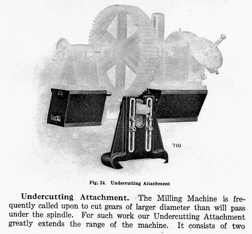 I expect I'll go with number two. It'll certainly build up the muscles, as I don't have power feed on the vertical axis.  Regards, Andrew Edit: Hmmm, the picture isn't very clear, for a better one look in my Odds 'n' Sods album Edited By Andrew Johnston on 02/03/2011 21:32:10 |
| Niloch | 02/03/2011 21:58:56 |
| 371 forum posts | Posted by Andrew Johnston on 01/03/2011 21:52:32: By the way, a universal mill is not one that has both vertical and horizontal capability. It specifically refers to a horizontal mill that has a swivelling table so that, with the aid of a suitable dividing head, it can be used to machine spiral features, such as flutes on a custom cutter, or a helical gear. Regards, Andrew Could the Swiss Aciera mill on the cover of MEW 171 be an example of your definition? However, it appears that some dyslexia has crept in and the machine is labelled as an Aceria both on the cover and in Roger Trewinnard's Re-furbishing article commencing on page 40. I could be hopelessly incorrect but lathes.co.uk does not list Aceria. The table is able to rotate laterally to 45deg; swivel 30 deg. off the horizontal and the head swivels 90 deg. in either direction. This is the same issue where a certain Mr Johnston gives us his Experiences with a Tormach CNC Vertical Mill!! |
| Steve Garnett | 02/03/2011 22:20:53 |
| 837 forum posts 27 photos | Posted by Nicholas Farr on 02/03/2011 11:27:26: Hi Steve, I guess what you ment is that there are horizonal milling machines that also have provisons with the suitable attachments (often an opional extra) to become a vertical milling machine, If I'd had a chance I was going to mention those, but I really am aware of the 'universal' concept as well! We haven't developed the concept fully anyway. For Colin's benefit we could also mention that there are different types of vertical mill, certainly in terms of turret, knee, round column vs Dovetail, CNC and all sorts of other details, I'm sure. Once you have your head around the basic principles of why milling machines are a good idea, then the scope of the subject is definitely the next thing to consider, isn't it? As for the 'good idea to have both' thing - well, how could I not agree? I'm very slowly restoring a Tom Senior M1 to its former state of glory (or something along those lines), and it has the knuckle head as well, so I'll have just that. |
| mgj | 02/03/2011 22:41:31 |
| 1017 forum posts 14 photos | Andrew- fortunately I think I'm not in quite the same boat as you, because I can see the problem, and mine is not so difficult.. With a vertical mill I have 2 extra bits of space. I have a lot more height, but also I can put the dividing head to one side of the spinde CL, so I have the space around the circle to give me room. I'll cut on the Y axis moving the work front to back. But that means I have to hang a bit of the dividing head over the edge of the table. Since the DH has a 5" centre height, I can use the raising block as a mount When I did the 3" engines final drive on a GHT VDH and a Dore Westbury, - that was about 8" dia and much more than a VDH was ever intended for. Again I cut on the Y axis, but hung the whole gear over the edge of the table. Used a C clamp to lock it, so the clamp and table took the force of the cut , and the VDH did the indexing. It worked, but i was looking for a better solution!! Where did you get your 6DP cutters from if you wouldn't mind saying. I need a total of 4. (Tracy and RDG seem to advertise) |
| mgj | 02/03/2011 23:02:38 |
| 1017 forum posts 14 photos | John deserves an answer. Will a scale in degrees around the edge of the table automatically line up with the scale on the handwheel. No - unless you hav some kind of resettable collar on the handwheel. In fact the scale round the edge, I don't think I have ever used. The handwheel - all depends on the ratio between the worm and wheel. so you have degees, and minutes which are 60ths of a degree, and probalby a vernier reading typically to 2 or 4 seconds of arc which are 60ths of a minute. Normally off the calculator you will get an answer in decimals of a degree which you will have to convert. So if you get an answer of say 7.46 deg. .46x60 = 27.6 minutes. The remainder you convert as well. so .6x60 = 36 seconds exactly. So 7.46 deg = 4 deg 27min 36 sec. I wish they would calibrate the scales decimally! Most tables have 60 or 90 to 1 ratios I think. 360/90 =4 deg per turn of the handwheel. 360/60 = 6deg per turn. Its most likely to be one of those two. I'm no expert on these things - just a user, so due apologies ot Grannies if you knew all that. Edited By mgj on 02/03/2011 23:03:21 |
| Andrew Johnston | 02/03/2011 23:16:21 |
7061 forum posts 719 photos | Hi mgj, I got two of my 6DP involute cutters, and all of the required 5DP cutters, from a surplus store in America via Ebay. That left me still needing a 6DP No.2 cutter. Personally I haven't found any of the usual UK advertisers to be particularly helpful. After a fruitless trawl around every stand at last years' Midlands ME show that looked like it might know what an involute cutter might be, I finally bought a new 6DP No.2 cutter from Victor Machinery Exchange in New York. It was listed as an 'import' which almost certainly means it was made in China. Total cost including shipping, VAT and inport duty was about £100. I would exclude RDG from the list of unhelpful suppliers. I have bought some 18DP cutters from them in the past, and have been pleased with them. However, all their cutters are (annoyingly) 14.5°PA, and I'm committed to 20°PA. I have 6DP 20°PA cutters numbers 6, 5 and 2. Which ones do you need? Regards, Andrew |
| Nicholas Farr | 03/03/2011 00:46:22 |
3988 forum posts 1799 photos | Hi John, sorry I'd forgot you asked about the graduations on the handwheel. I have a Vertex HV6 and I have looked on thier website (below) and it says that the coller is graduated in steps of 1 minute and the vernier scale makes settings down to 10 secounds possible. The ratio of the table is 90:1 and the coller also has 0, 1, 2 and 3 quarted making the 4 degrees that mgj metioned, there is also a 30 midway between each of the above mentioned digits. (see pic below) The vernier has devisions of 60-0-60 in 7 graduations. I have not used this facility myself. but the coller is moveable by loosening the grub screw that can be seen, tuning to the desiered position and then tightening the screw. Once you have a reference mark alined and then turning the table noting how many dregrees, mins and secs you require, it can be done by counting the degrees by the four numbers X the number of rotations of the handwheel, plus the number of minutes on the graduations and then lining up one of the graduation marks to the number of seconds required on the vernier scale. I hope I've got that correct and it makes sense, yours may be slightly different, but the proceedure should be much the same.
http://www.vertex-tw.com.tw/products/products_list.php?language=_eng&cid=10 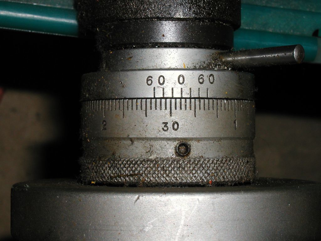 Regards Nick. Edited By Nicholas Farr on 03/03/2011 00:53:42 |
| Nicholas Farr | 03/03/2011 01:27:47 |
3988 forum posts 1799 photos | Hi, further to my previous post above, my table must be an older version than the one described on the website, as studying it in more detail, the graduations on mine are in 2 minute steps, hence the 30 markings denoting half a degree. The vernier steps are of 20 seconds, therefore setting the table to 10 seconds is approximation by setting the wheel graduations between the appropreate vernier graduations.
So I reckon my dial is reading 1 degree 25 minutes and 30 seconds, right to left.
Regards Nick. Edited By Nicholas Farr on 03/03/2011 01:35:56 |
| John Olsen | 03/03/2011 08:02:59 |
| 1294 forum posts 108 photos 1 articles | My Vertex rotary table (8 inch size) has an adjustable fiducial for the scale on the table part, so you can set the Vernier part on an exact mark and then adjust the fiducial to also be on a mark as well, avoiding ambiguity. regards John |
Please login to post a reply.
Magazine Locator
Want the latest issue of Model Engineer or Model Engineers' Workshop? Use our magazine locator links to find your nearest stockist!
Sign up to our Newsletter
Sign up to our newsletter and get a free digital issue.
You can unsubscribe at anytime. View our privacy policy at www.mortons.co.uk/privacy
Latest Forum Posts
- *Oct 2023: FORUM MIGRATION TIMELINE*
05/10/2023 07:57:11 - Making ER11 collet chuck
05/10/2023 07:56:24 - What did you do today? 2023
05/10/2023 07:25:01 - Orrery
05/10/2023 06:00:41 - Wera hand-tools
05/10/2023 05:47:07 - New member
05/10/2023 04:40:11 - Problems with external pot on at1 vfd
05/10/2023 00:06:32 - Drain plug
04/10/2023 23:36:17 - digi phase converter for 10 machines.....
04/10/2023 23:13:48 - Winter Storage Of Locomotives
04/10/2023 21:02:11 - More Latest Posts...
- View All Topics
Support Our Partners


Shopping Partners
Subscription Offer

Latest "For Sale" Ads
- Reeves** - Rebuilt Royal Scot by Martin Evans
by John Broughton
£300.00 - BRITANNIA 5" GAUGE James Perrier
by Jon Seabright 1
£2,500.00 - Drill Grinder - for restoration
by Nigel Graham 2
£0.00 - WARCO WM18 MILLING MACHINE
by Alex Chudley
£1,200.00 - MYFORD SUPER 7 LATHE
by Alex Chudley
£2,000.00 - More "For Sale" Ads...
Latest "Wanted" Ads
- D1-3 backplate
by Michael Horley
Price Not Specified - fixed steady for a Colchester bantam mark1 800
by George Jervis
Price Not Specified - lbsc pansy
by JACK SIDEBOTHAM
Price Not Specified - Pratt Burnerd multifit chuck key.
by Tim Riome
Price Not Specified - BANDSAW BLADE WELDER
by HUGH
Price Not Specified - More "Wanted" Ads...
Get In Touch!
Do you want to contact the Model Engineer and Model Engineers' Workshop team?
You can contact us by phone, mail or email about the magazines including becoming a contributor, submitting reader's letters or making queries about articles. You can also get in touch about this website, advertising or other general issues.
Click THIS LINK for full contact details.
For subscription issues please see THIS LINK.
Digital Back Issues


Donate

 Register
 Log-in
Model Engineer Magazine
- Percival Marshall
- M.E. History
- LittleLEC
- M.E. Clock

ME Workshop
- An Adcock
- & Shipley
- Horizontal
- Mill

Subscribe Now
- Great savings
- Delivered to your door

Pre-order your copy!
- Delivered to your doorstep!
- Free UK delivery!
All Forum Topics > Beginners questions > Rotary Table / milling machine