Forum sponsored by:

Swage / Pipe Fabrication
| Anthony Salisbury | 03/01/2011 13:41:28 |
| 32 forum posts 11 photos | Hi all,
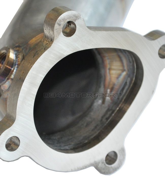
The picture below is an example not exactly the same as what I'm after but a good example and wondered how to form the bit of the pipe directly behind the flange. It is an egg type shape as though it have been swaged out of a peice of pipe? How would this be formed industrially?
Any help would be good,
Regards,
Ant
 |
| RJW | 03/01/2011 14:39:07 |
| 343 forum posts 36 photos | Ant, the flange assembly in the photo, looks suspiciously like the turbine outlet / exhaust front pipe for a turbocharger, and the 'Egg' shape formed to accommodate the gasflow from both the turbine outlet and a wastegate valve. My guess for commercial applications, is that a press would be used similar to that used for making brake pipes. The pipe would be clamped in specially constructed 'Female' split jawed jig, then a similar 'Male' press tool would be pressed into it - either by mechanical or hydraulic means. Also possible that the flange is made as a separate component, then welded to the pipe end, which would simplify manufacture of the flange and press tools. Back in the late 1970's I was manufacturing turbo systems for automotive applications. No one other than SAAB or Porsche had a turbo car on the road at that time, so everything had to be hand made, and the turbo's & wastegates sourced from anywhere they could be had.(IHI, RayJay, KKK, etc). Flanges had to be made to suit individual turbo types, and then adapted to fit standard manifolding, or a complete manifold made. The flanges were generally flame cut from sheet steel (one offs) or cast iron to pattern for quantity, then finished by hand. Pipe bends were available in various diameters, which then had to be shaped to the flanges similar to that shown above. Generally, I just got the pipe end red hot, and hand beat the pipe end into shape to suit the flange, then when happy with the shape, trim the end with a grinder and electric (stick) welded together. I never had one come apart, and those things used to get white hot on the dyno! I'll upload some photo's of a Porsche 911 I did in 1980, also have some of a Mini 1100 Special, Landrover and other gear somewhere.! (long time before digicam's unfortunately)! Best regards John |
| John Olsen | 03/01/2011 22:50:14 |
| 1294 forum posts 108 photos 1 articles | I had occasion to do something like this once in copper, not for a turbo obviously, and I made a female former out of MDF, and then beat the copper out from the inside until it matched nicely. The main difficulty was getting enough force onto the copper, since the tube was only 45mm diameter, so there wasn't a lot of room to work. regards John |
| Stub Mandrel | 07/01/2011 20:00:28 |
 4318 forum posts 291 photos 1 articles | Nice work John! Neil |
| RJW | 22/01/2011 11:26:38 |
| 343 forum posts 36 photos | Thanks Neil, have dug out some old photo's of the mini I converted, will scan and upload images later. Best regards, John |
Please login to post a reply.
Magazine Locator
Want the latest issue of Model Engineer or Model Engineers' Workshop? Use our magazine locator links to find your nearest stockist!
Sign up to our Newsletter
Sign up to our newsletter and get a free digital issue.
You can unsubscribe at anytime. View our privacy policy at www.mortons.co.uk/privacy
Latest Forum Posts
- hemingway ball turner
04/07/2025 14:40:26 - *Oct 2023: FORUM MIGRATION TIMELINE*
05/10/2023 07:57:11 - Making ER11 collet chuck
05/10/2023 07:56:24 - What did you do today? 2023
05/10/2023 07:25:01 - Orrery
05/10/2023 06:00:41 - Wera hand-tools
05/10/2023 05:47:07 - New member
05/10/2023 04:40:11 - Problems with external pot on at1 vfd
05/10/2023 00:06:32 - Drain plug
04/10/2023 23:36:17 - digi phase converter for 10 machines.....
04/10/2023 23:13:48 - More Latest Posts...
- View All Topics
Support Our Partners


Shopping Partners
Subscription Offer

Latest "For Sale" Ads
- Reeves** - Rebuilt Royal Scot by Martin Evans
by John Broughton
£300.00 - BRITANNIA 5" GAUGE James Perrier
by Jon Seabright 1
£2,500.00 - Drill Grinder - for restoration
by Nigel Graham 2
£0.00 - WARCO WM18 MILLING MACHINE
by Alex Chudley
£1,200.00 - MYFORD SUPER 7 LATHE
by Alex Chudley
£2,000.00 - More "For Sale" Ads...
Latest "Wanted" Ads
- D1-3 backplate
by Michael Horley
Price Not Specified - fixed steady for a Colchester bantam mark1 800
by George Jervis
Price Not Specified - lbsc pansy
by JACK SIDEBOTHAM
Price Not Specified - Pratt Burnerd multifit chuck key.
by Tim Riome
Price Not Specified - BANDSAW BLADE WELDER
by HUGH
Price Not Specified - More "Wanted" Ads...
Get In Touch!
Do you want to contact the Model Engineer and Model Engineers' Workshop team?
You can contact us by phone, mail or email about the magazines including becoming a contributor, submitting reader's letters or making queries about articles. You can also get in touch about this website, advertising or other general issues.
Click THIS LINK for full contact details.
For subscription issues please see THIS LINK.
Digital Back Issues


Donate

 Register
 Log-in
Model Engineer Magazine
- Percival Marshall
- M.E. History
- LittleLEC
- M.E. Clock

ME Workshop
- An Adcock
- & Shipley
- Horizontal
- Mill

Subscribe Now
- Great savings
- Delivered to your door

Pre-order your copy!
- Delivered to your doorstep!
- Free UK delivery!
All Forum Topics > Workshop Techniques > Swage / Pipe Fabrication