Forum sponsored by:

Die for Bending Instrument Bow Underslides
| Mike Donnerstag | 13/08/2023 17:25:20 |
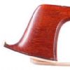 231 forum posts 53 photos | As a maker of instrument bows, I need to bend 0.25mm sterling silver sheet with two sharp bends which must be parallel and of an given width. I currently use only a simple mild steel male die, with which I press the silver sheet using a vice, backed up with rubber to form the 'female die'. The die is shown below:
This works, though as I need to make several more of a different width, I though I'd better consider my options.
I have several questions: 1) In order to ensure the folds are as sharp as possible, would carbon-steel/gauge plate be better for the male die instead of mild steel? 2) What is the purpose of the two cut-outs in the male die in the above photograph? They have two pieces of metal that fit in the slots, perhaps a softer metal? 3) Any information on materials I should use for the male and female dies? Mike
|
| Jeff Dayman | 13/08/2023 17:31:59 |
| 2356 forum posts 47 photos | Since we have no idea what the finished bent part needs to look like, it's pretty hard to address your questions. More info please. Generally speaking, gauge plate will have much longer life than mild steel in many tooling situations. Whether its' extra cost and the lower machinability of gauge plate are justified depends on the loads it will see and how many operations it needs to perform. |
| Neil A | 13/08/2023 19:19:56 |
| 160 forum posts | I can only think that the cut-outs in the die are some sort of fine adjustment to top surface either to correct for distortion caused by hardening the part or maybe slightly modify the thickness of the part being pressed. I could be completely wrong, but I can't think of any other purpose as the recess in the mating part seems to be flat bottomed. It's an interesting question. Neil |
| Mike Donnerstag | 13/08/2023 19:45:50 |
231 forum posts 53 photos | Posted by Jeff Dayman on 13/08/2023 17:31:59:
Since we have no idea what the finished bent part needs to look like, it's pretty hard to address your questions. More info please. Generally speaking, gauge plate will have much longer life than mild steel in many tooling situations. Whether its' extra cost and the lower machinability of gauge plate are justified depends on the loads it will see and how many operations it needs to perform. Apologies Jeff - you're absolutely right. I've attached a drawing below:
|
| Jeff Dayman | 13/08/2023 21:25:50 |
| 2356 forum posts 47 photos | Thanks Mike for the drawing. I'm not sure of the tensile strength of the silver you are using, but based on previous jobs I have worked on with silver alloys used in electrical contacts, I estimate the bend force per 48 mm long bend to be a few hundred pounds max. I think mild steel would be fine for the dies unless you plan to run millions and millions of the parts. If you use higher strength material rather than silver, or plan to run huge qty's, use gauge plate. Just my opinion. PS- to your question 2 about re "cutouts" - if you are referring to the two holes at the inner ends of the thin slots, they're probably done as a crack prevention strategy and possibly as a sawing blade relief at end of cuts. |
| Mike Donnerstag | 14/08/2023 07:02:56 |
231 forum posts 53 photos | The complex bending tool in the photograph in my first post is made for use with a hammer. I’m wondering whether the holes, slots and inserted metal are some kind of way in which to spread this pressure evenly across the silver sheet as it is being formed. Has anyone seen anything similar to this? Mike |
| SillyOldDuffer | 14/08/2023 11:07:56 |
| 10668 forum posts 2415 photos | Posted by Mike Donnerstag on 14/08/2023 07:02:56:
The complex bending tool in the photograph in my first post is made for use with a hammer. I’m wondering whether the holes, slots and inserted metal are some kind of way in which to spread this pressure evenly across the silver sheet as it is being formed. ... Mike Makes sense to me, except maybe the other way round. I imagine the springs spread the pressure out from the centre towards the ends. The middle of the silver bends first, and the spring action causes slightly less force to be applied at the ends. It would make the die less likely to damage the ends. Dave |
| JasonB | 14/08/2023 13:11:39 |
 25215 forum posts 3105 photos 1 articles | When you bend flat strip it does tend to thicken slightly at the edges so the slots in the male part of the die look like they could be expanded slightly by the inserted "L" shaped shims so the die exerts more pressure towards the ends to flatten out any local thickening Edited By JasonB on 14/08/2023 13:12:13 |
| Tim Stevens | 14/08/2023 14:39:45 |
 1779 forum posts 1 photos | I can help, perhaps, from my own experience as a silversmith apprentice. To make sharp corners in a silver box, I cut a groove along the line of the desired bend. The tool was made from a bar of silver steel, heated red and turned over at the end. then filed so that it cut a 90 degree slot when pulled along. And then hardened and stoned to the exact shape. A thick steel rule was clamped firmly to the flat plate, and the tool drawn along by hand several times, to remove about 2/3 of the thickness, along the length of the fold required. The same operation was then done for the other folds in that workpiece. Two parallel grooves, and two more at 90 degrees, gives the base and four sides of a box - and four off-cuts in the corners. These latter pieces were carefully removed and the edges filed smooth at the correct angle. Then the sides were folded up to bring the edges together, and propped on a heatproof slab with the sides held firmly together. Borax flux was then applied, and the joints were silver-soldered to give a smooth, rounded run of solder down each side and along each of the base edges. this resulted in the outer edges of the bottom being sharper than could be achieved by bending, and with no chance of roughness as the thinner metal was indeed bent rather than soldered, on the outside. At the same time, filling the join with solder made it much stronger (firmer) than a simple bend. For your purposes, the tool (and the grooves) should be made sharper (say 40 or 60 degrees, not 90) to suit the geometry of your bend. But remember that if you need the result to have the stiffness of hard-rolled metal, this process might not be ideal as the soldering will surely anneal it. I hope this offers a way forward Cheers, Tim |
| Tim Stevens | 14/08/2023 14:57:39 |
1779 forum posts 1 photos | Another thought: If you need the metal hard, and the bend is gentle, you could try the effect of coining the material. This means that you make both halves of the die of a hardened material (and chunky) and start with a strip of silver slightly thicker than the final product. Then you force the two halves of the die together so that the metal is squeezed to the final shape. A decent large vice would be good for this, or a powerful jack. A big fly-press can also serve, but you have less control over the amount of pressure. The term coining relates to the way coinage and medals are produced. The metal is forced into every last detail of a hard steel die each side, hardening the metal as it does so. If t he dies are nicely finished, the result should need little further work. Any file marks or emery scratches will show in the silver, so do spend time to ensure the finish of the dies is good, and you will save time finishing the resulting presswork. Cheers, Tim |
| old mart | 15/08/2023 20:57:30 |
| 4655 forum posts 304 photos | You will get more precision if you use a small fly press with tooling to fit it. The trouble with trying to get bends is the springback that varies with every metal alloy. The most stable results are to bend slightly past the design angle and then use minimum force to bring the bend back to optimum. I did a lot of straightening of part machined aircraft components part way through their manufacture and there was always some springback to take into account. I kept a book with the "recipies" for parts as once the first had been successfully finished, the others took 1/10 of the time and this also worked for future batches. |


Please login to post a reply.
Magazine Locator
Want the latest issue of Model Engineer or Model Engineers' Workshop? Use our magazine locator links to find your nearest stockist!
Sign up to our Newsletter
Sign up to our newsletter and get a free digital issue.
You can unsubscribe at anytime. View our privacy policy at www.mortons.co.uk/privacy
Latest Forum Posts
- *Oct 2023: FORUM MIGRATION TIMELINE*
05/10/2023 07:57:11 - Making ER11 collet chuck
05/10/2023 07:56:24 - What did you do today? 2023
05/10/2023 07:25:01 - Orrery
05/10/2023 06:00:41 - Wera hand-tools
05/10/2023 05:47:07 - New member
05/10/2023 04:40:11 - Problems with external pot on at1 vfd
05/10/2023 00:06:32 - Drain plug
04/10/2023 23:36:17 - digi phase converter for 10 machines.....
04/10/2023 23:13:48 - Winter Storage Of Locomotives
04/10/2023 21:02:11 - More Latest Posts...
- View All Topics
Support Our Partners


Shopping Partners
Subscription Offer

Latest "For Sale" Ads
- Reeves** - Rebuilt Royal Scot by Martin Evans
by John Broughton
£300.00 - BRITANNIA 5" GAUGE James Perrier
by Jon Seabright 1
£2,500.00 - Drill Grinder - for restoration
by Nigel Graham 2
£0.00 - WARCO WM18 MILLING MACHINE
by Alex Chudley
£1,200.00 - MYFORD SUPER 7 LATHE
by Alex Chudley
£2,000.00 - More "For Sale" Ads...
Latest "Wanted" Ads
- D1-3 backplate
by Michael Horley
Price Not Specified - fixed steady for a Colchester bantam mark1 800
by George Jervis
Price Not Specified - lbsc pansy
by JACK SIDEBOTHAM
Price Not Specified - Pratt Burnerd multifit chuck key.
by Tim Riome
Price Not Specified - BANDSAW BLADE WELDER
by HUGH
Price Not Specified - More "Wanted" Ads...
Get In Touch!
Do you want to contact the Model Engineer and Model Engineers' Workshop team?
You can contact us by phone, mail or email about the magazines including becoming a contributor, submitting reader's letters or making queries about articles. You can also get in touch about this website, advertising or other general issues.
Click THIS LINK for full contact details.
For subscription issues please see THIS LINK.
Digital Back Issues


Donate

 Register
 Log-in
Model Engineer Magazine
- Percival Marshall
- M.E. History
- LittleLEC
- M.E. Clock

ME Workshop
- An Adcock
- & Shipley
- Horizontal
- Mill

Subscribe Now
- Great savings
- Delivered to your door

Pre-order your copy!
- Delivered to your doorstep!
- Free UK delivery!
All Forum Topics > Workshop Tools and Tooling > Die for Bending Instrument Bow Underslides