Forum sponsored by:

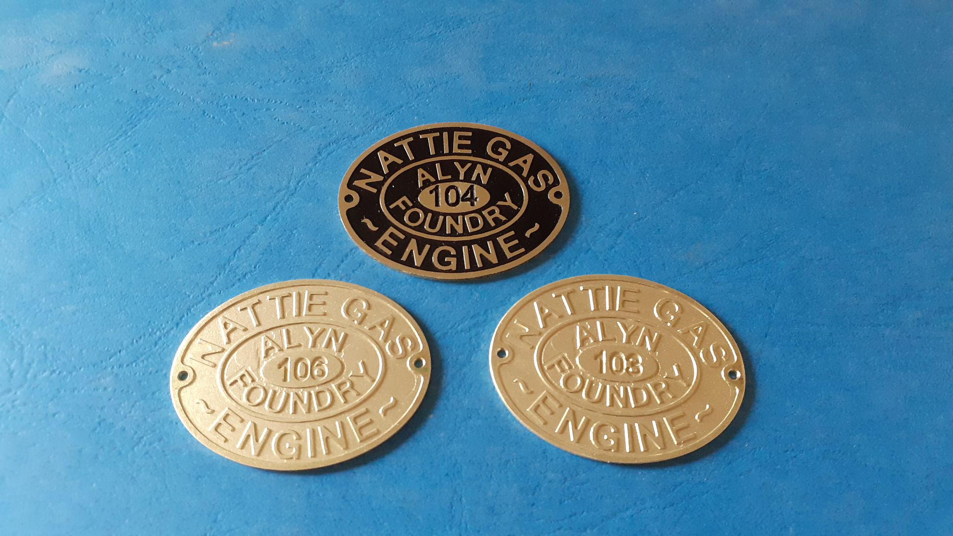
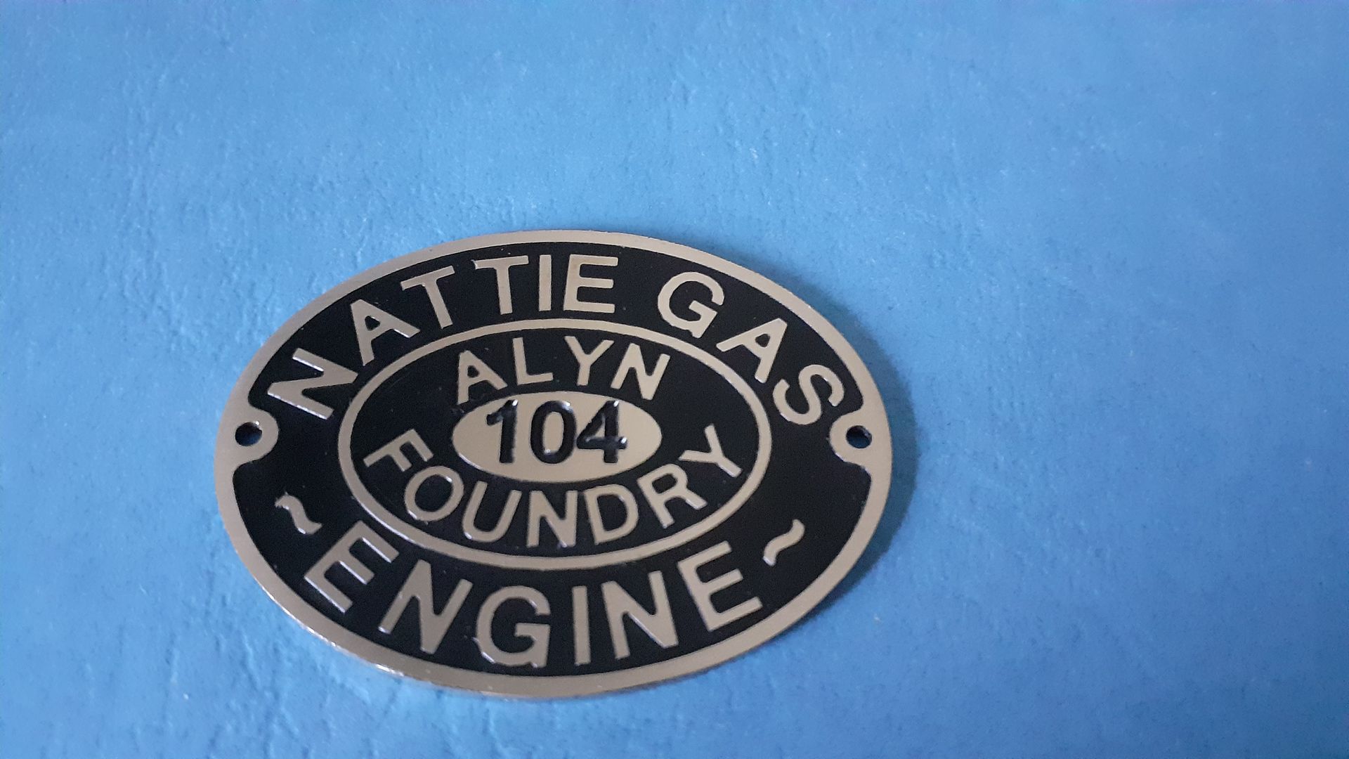
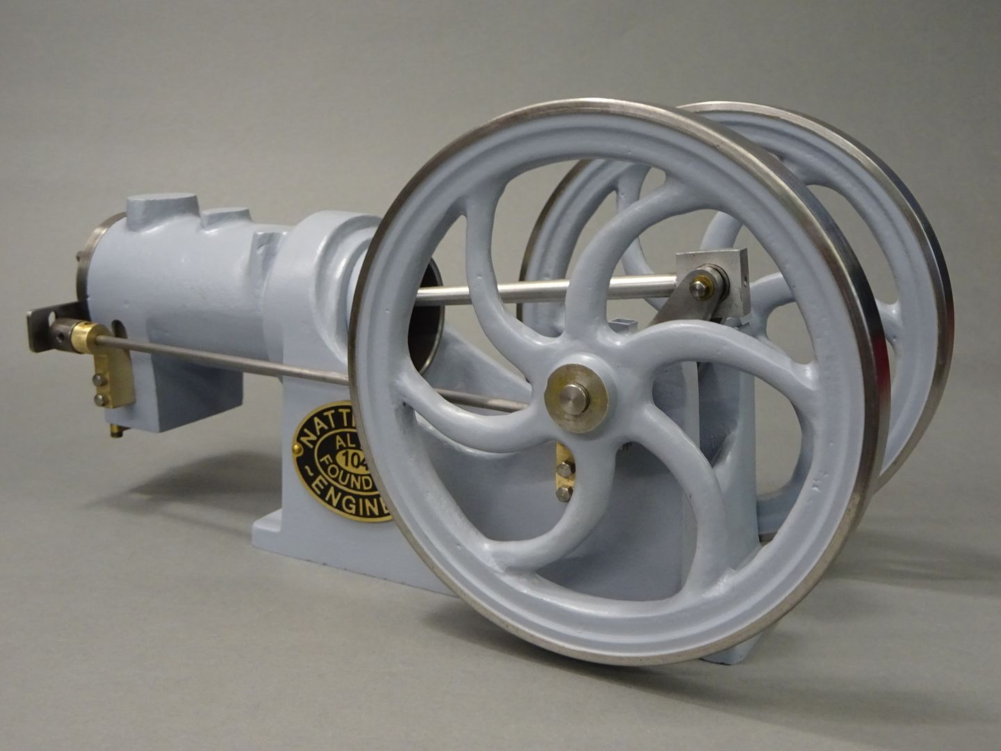
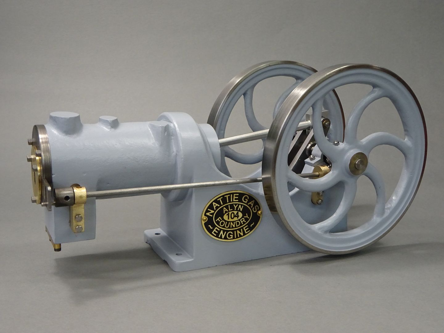
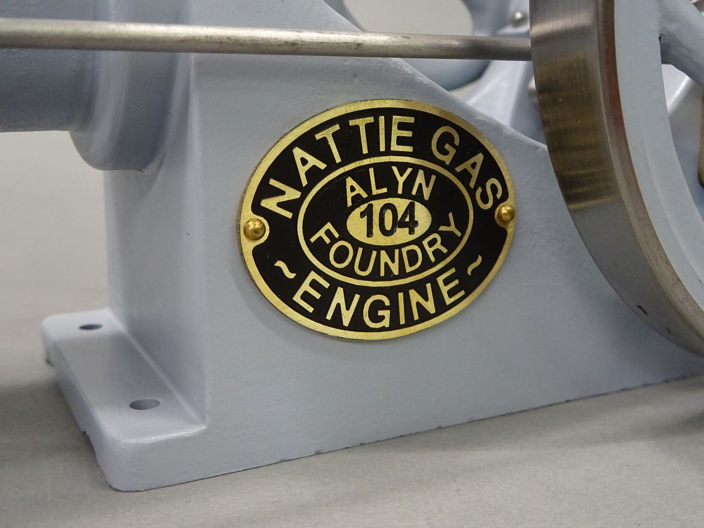
Alyn Foundry Nattie #104
| JasonB | 16/06/2023 20:07:17 |
 25215 forum posts 3105 photos 1 articles | Those not familiar with the background history of Alyn Foundry's Nattie would do well to read Grahams thread here |
| JasonB | 25/06/2023 19:24:26 |
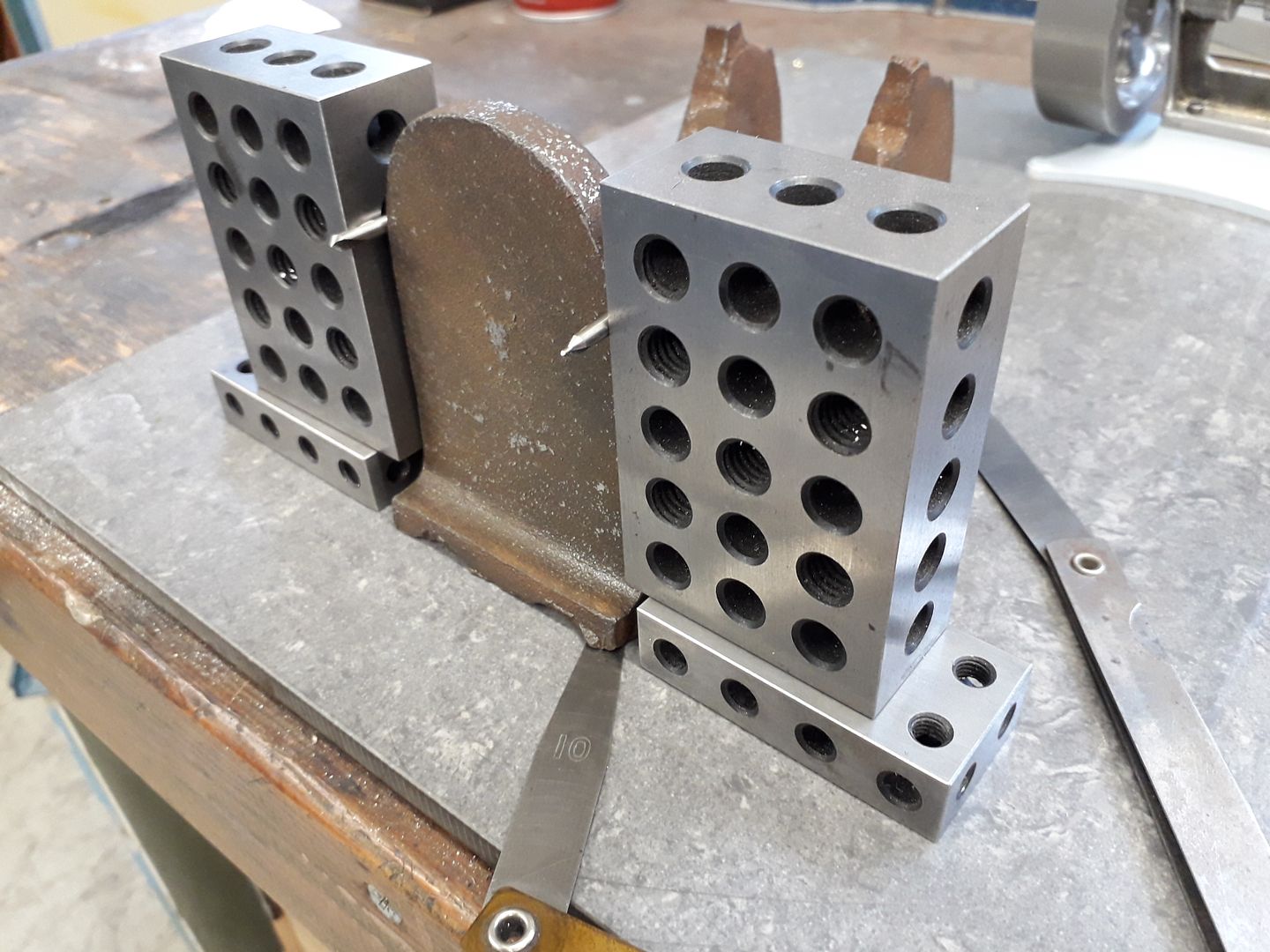
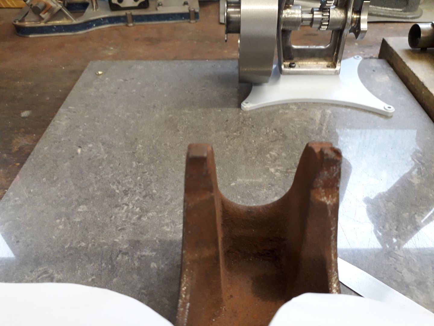
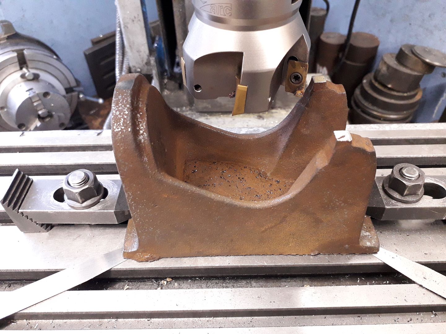
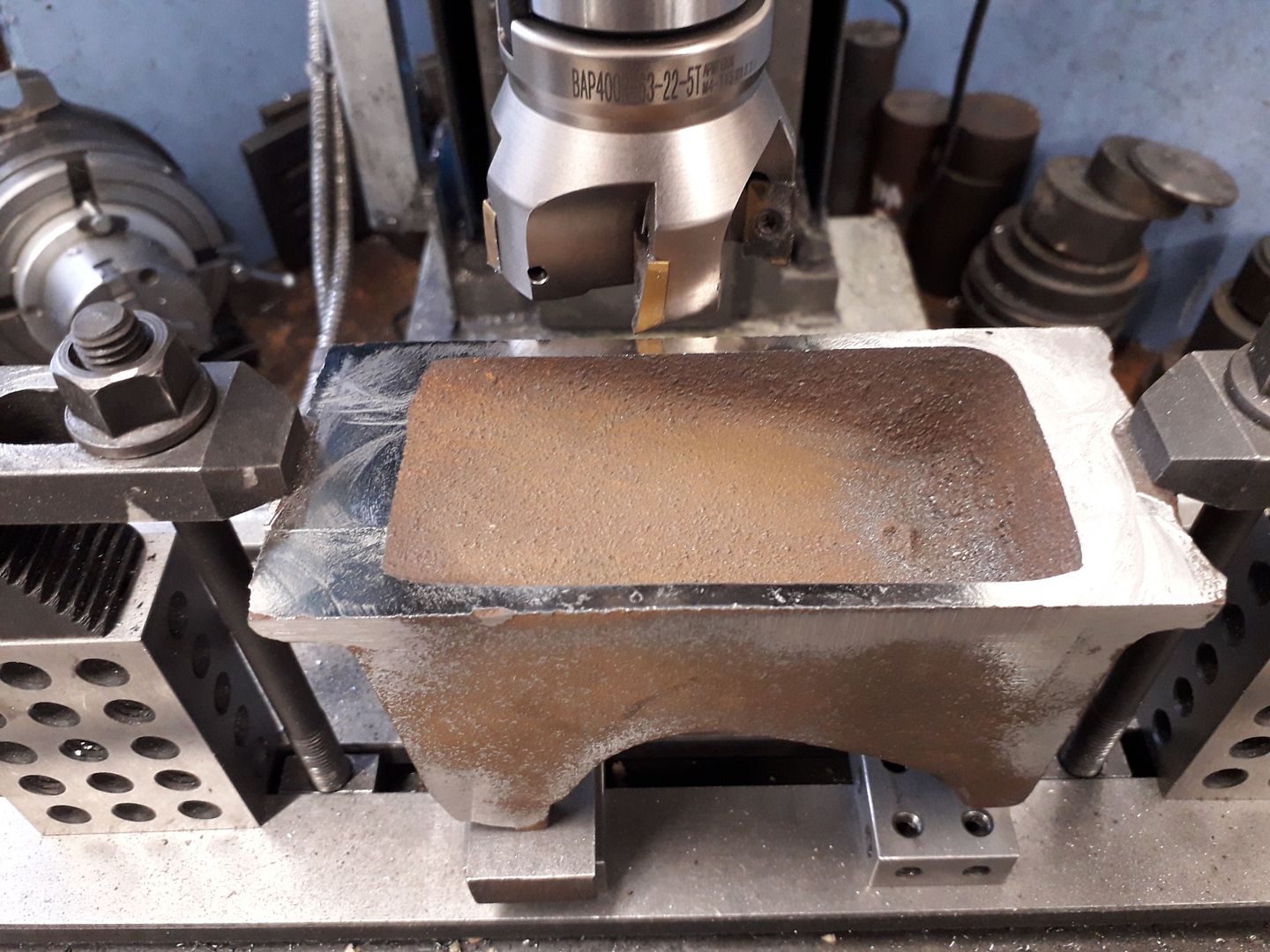
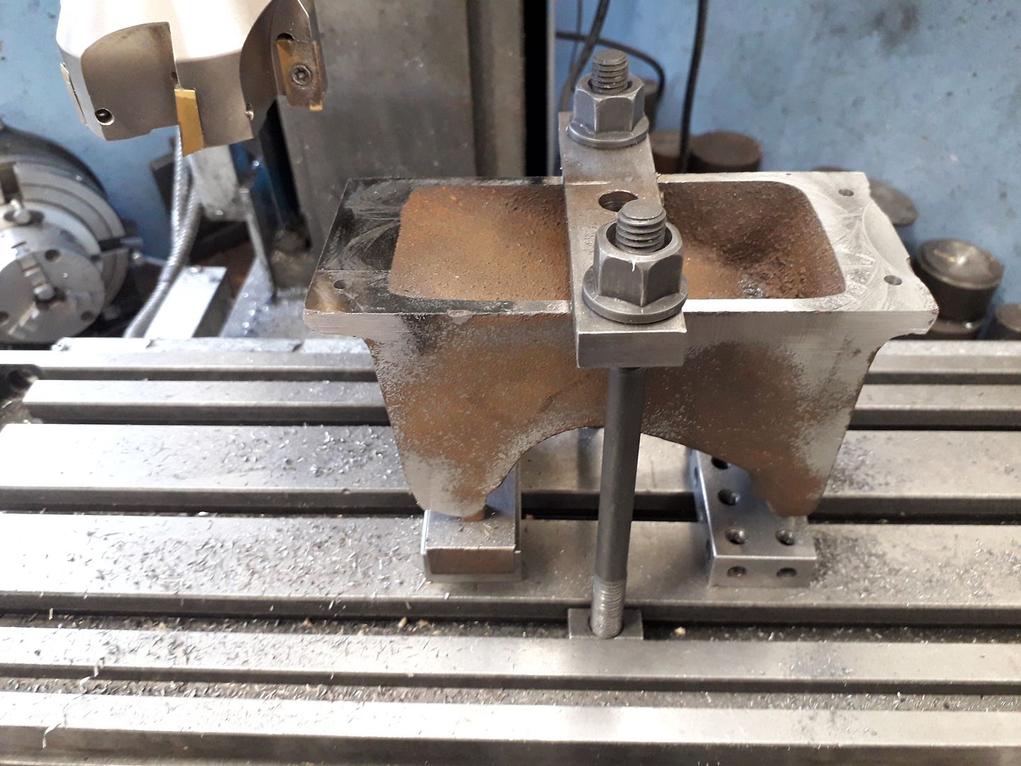
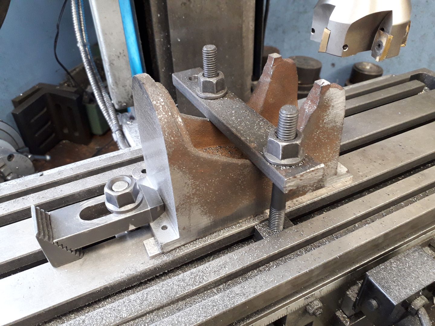
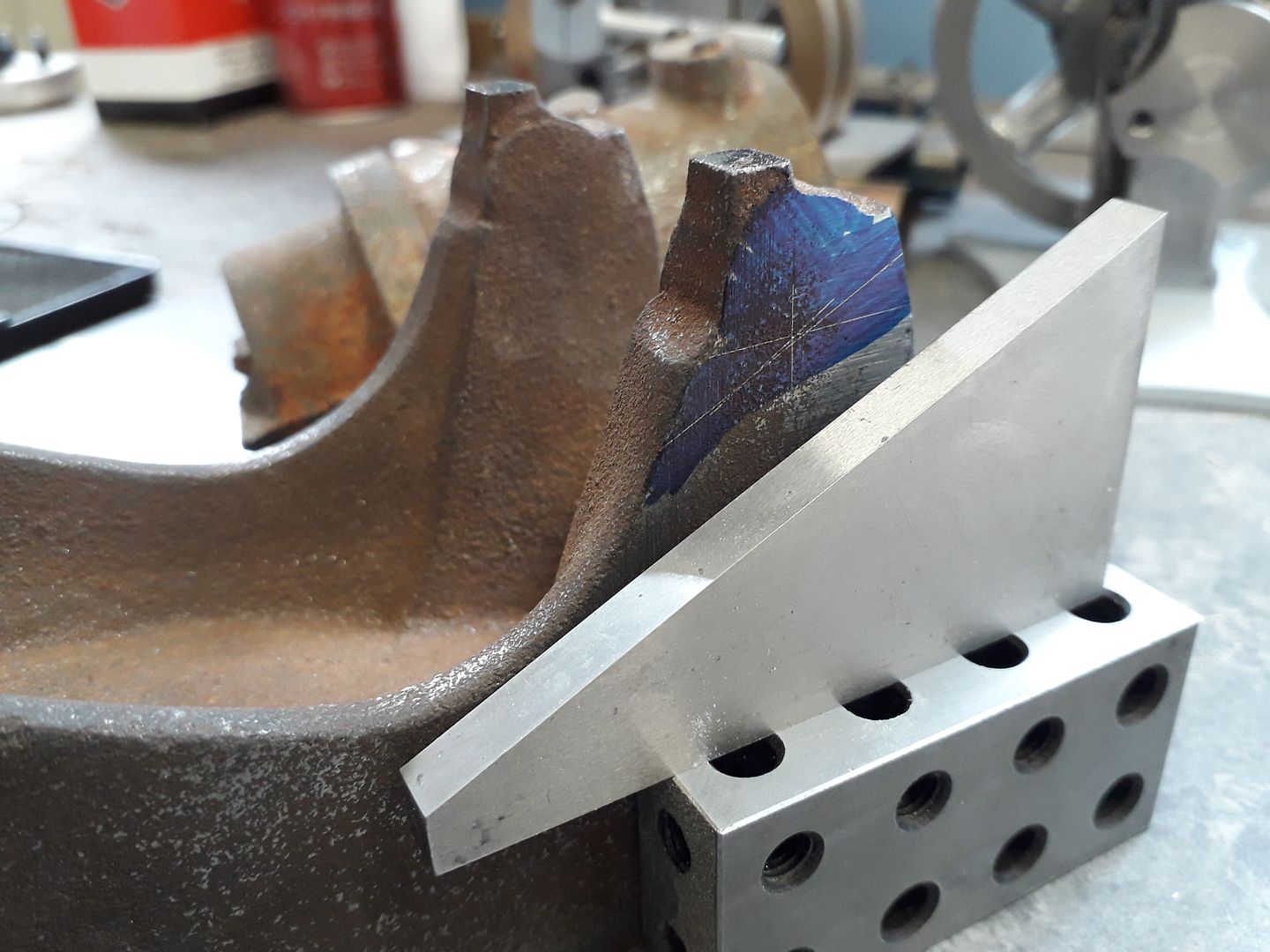
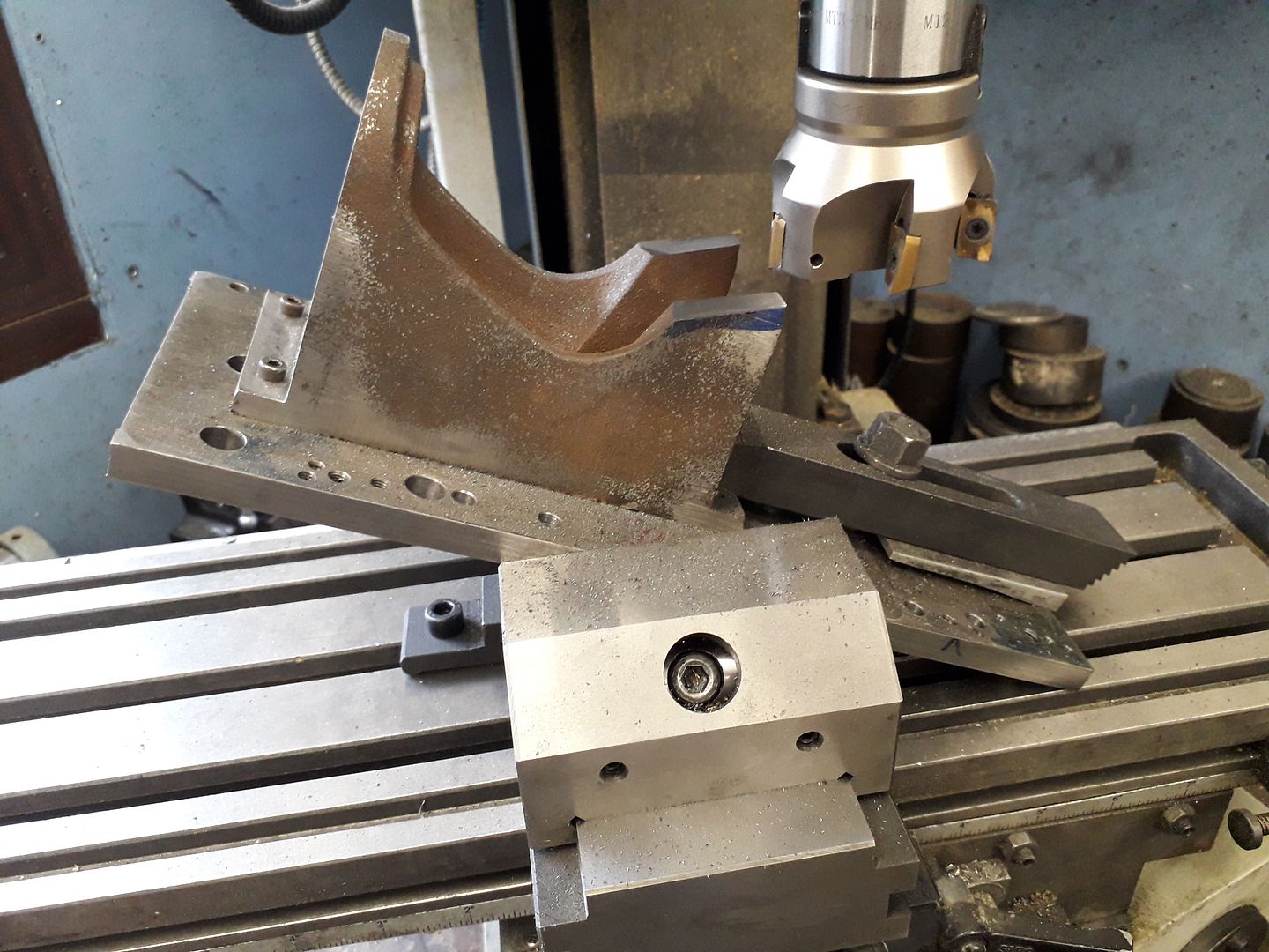
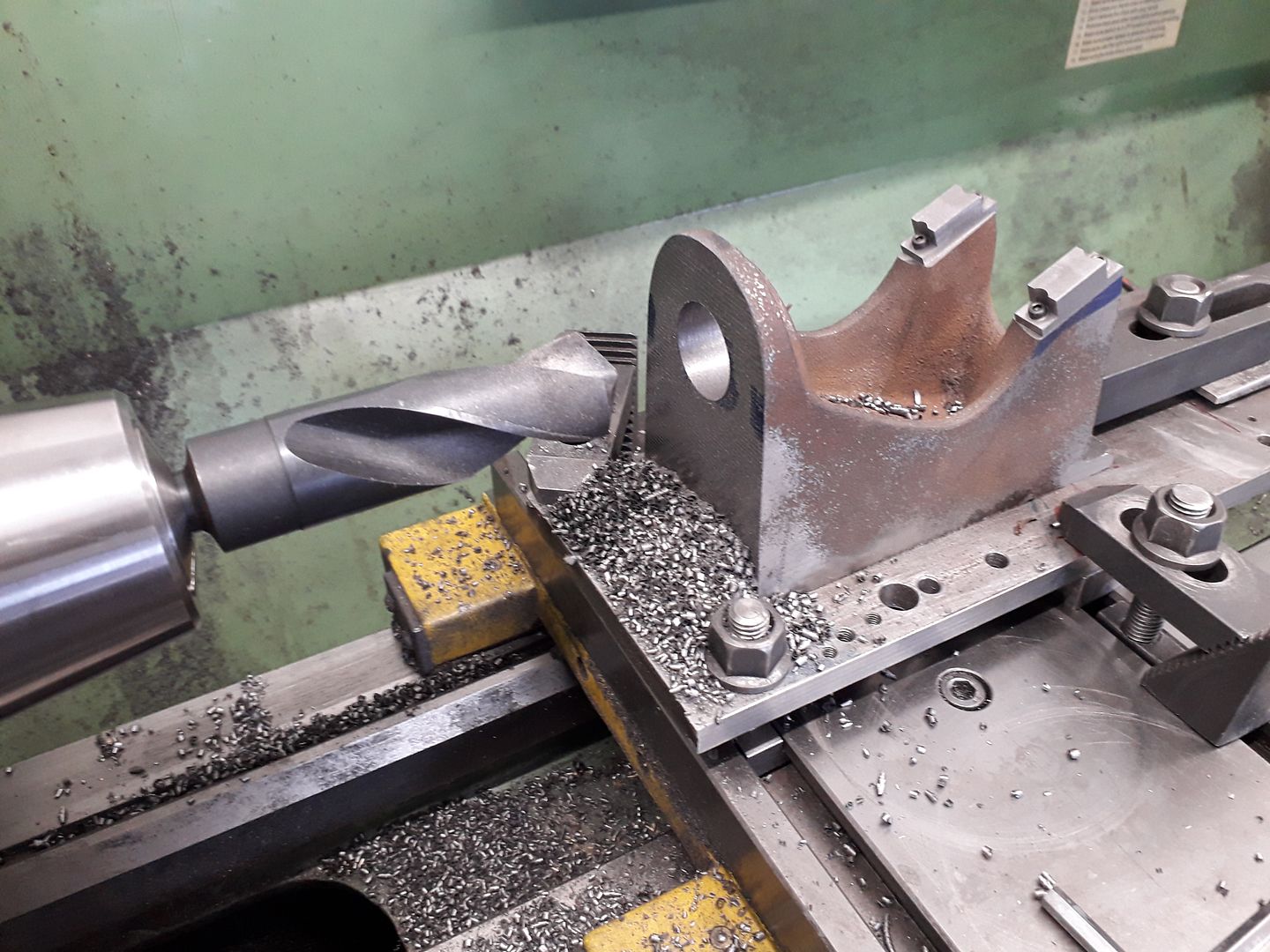
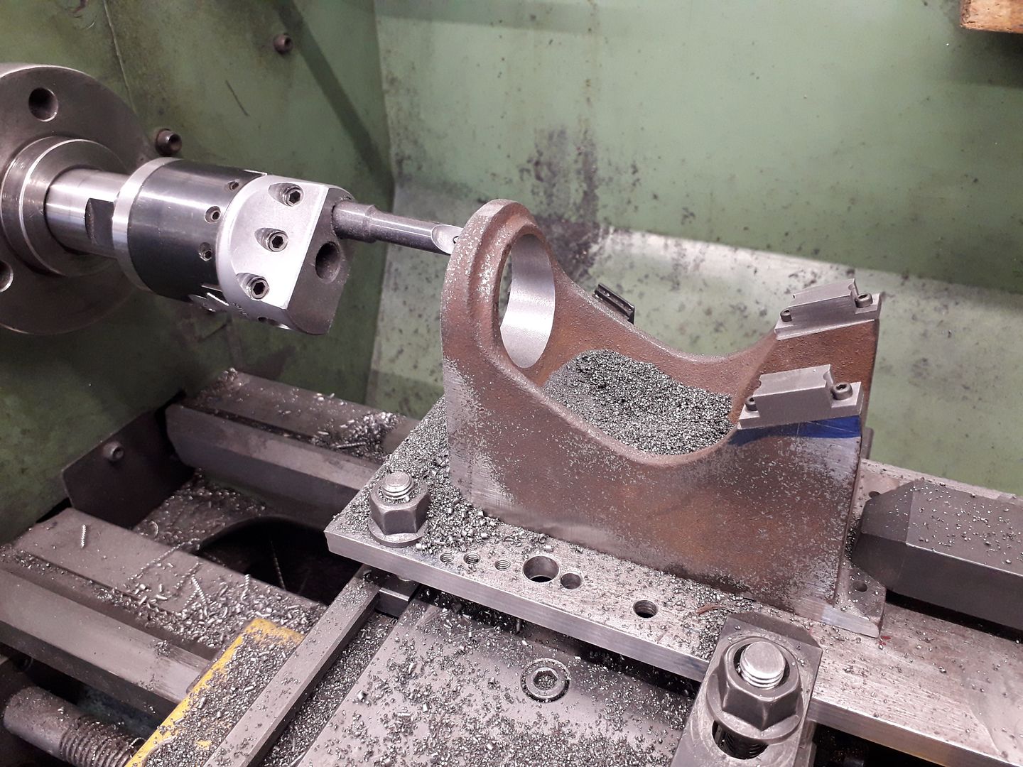
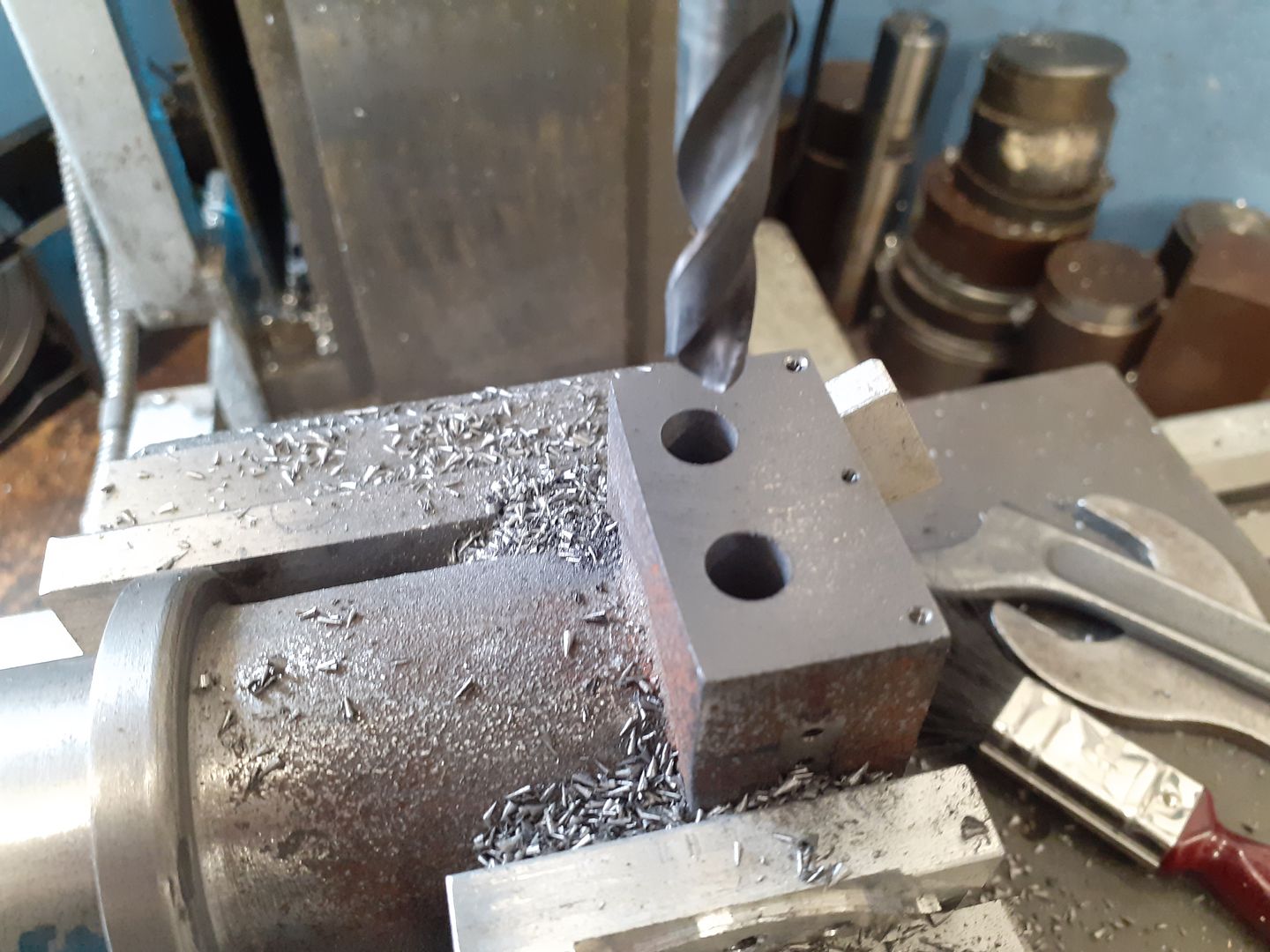
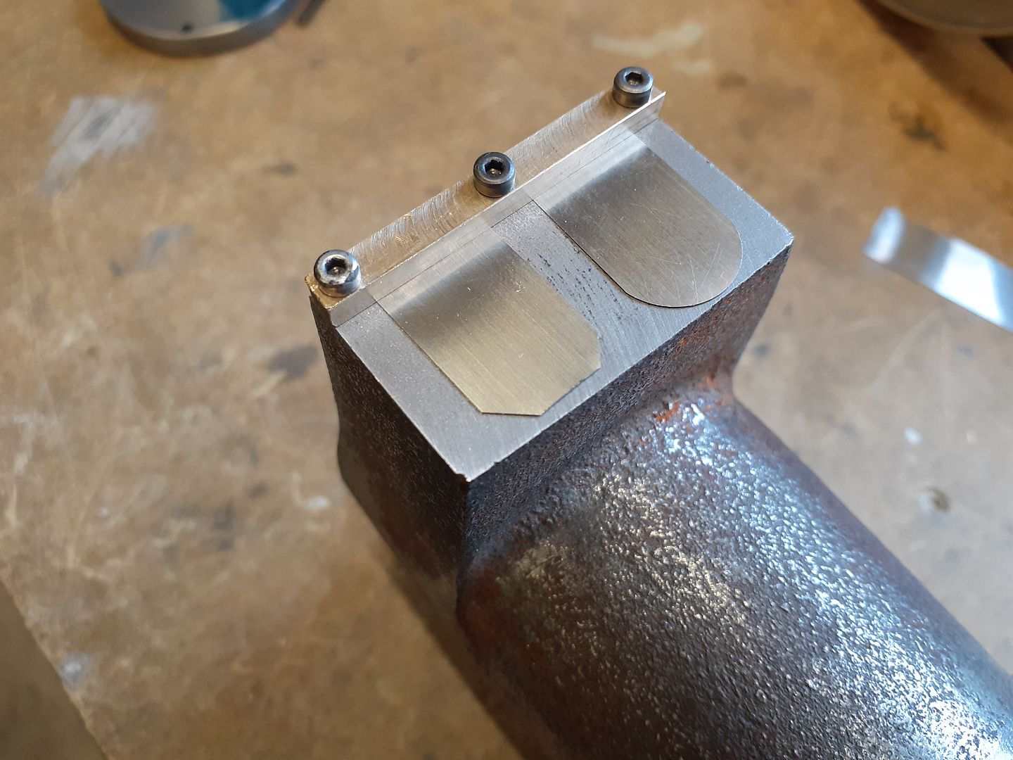
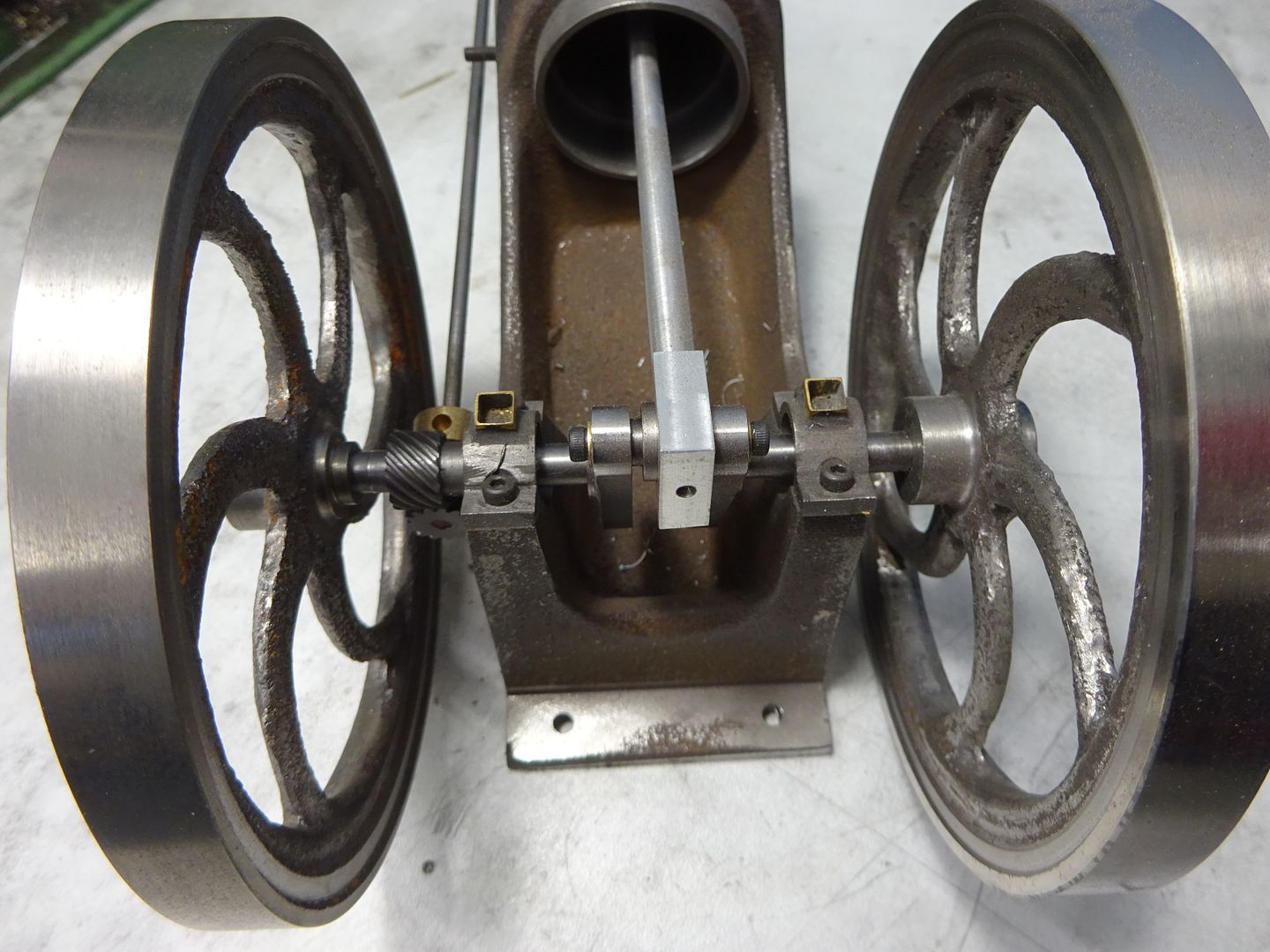
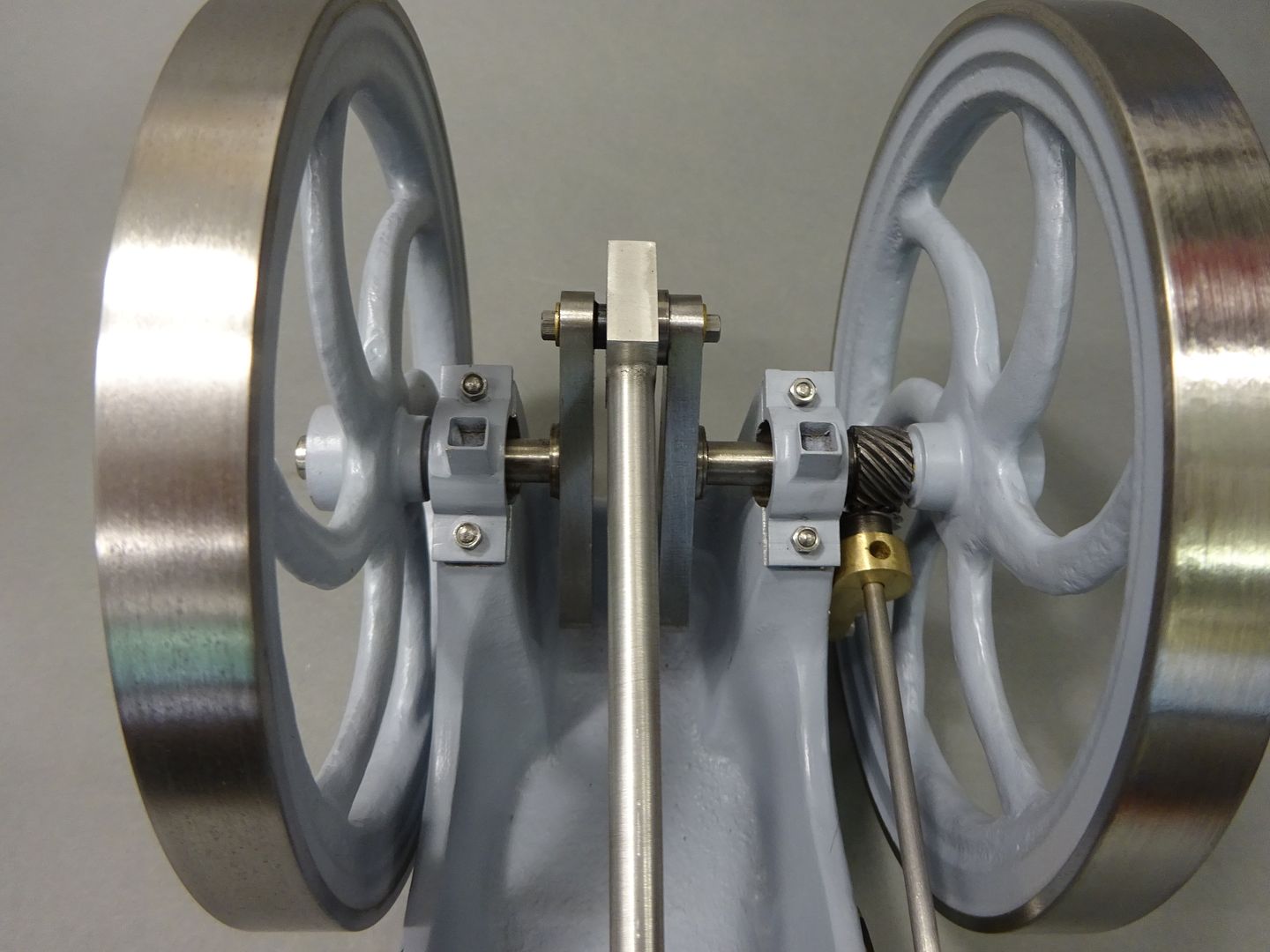
25215 forum posts 3105 photos 1 articles | So with the machining plate made the casting was screwed into place and it was then easy to set the angle of the plate and also make sure it was true to the mill axis. I then used an insert shell mill to remove the two integral casting caps after which holes were drilled & tapped for the bearing caps. |
| JasonB | 04/07/2023 18:53:00 |
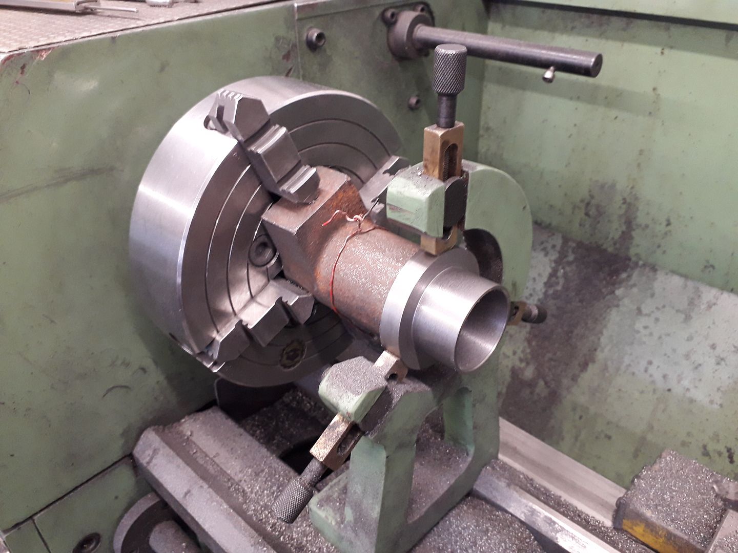
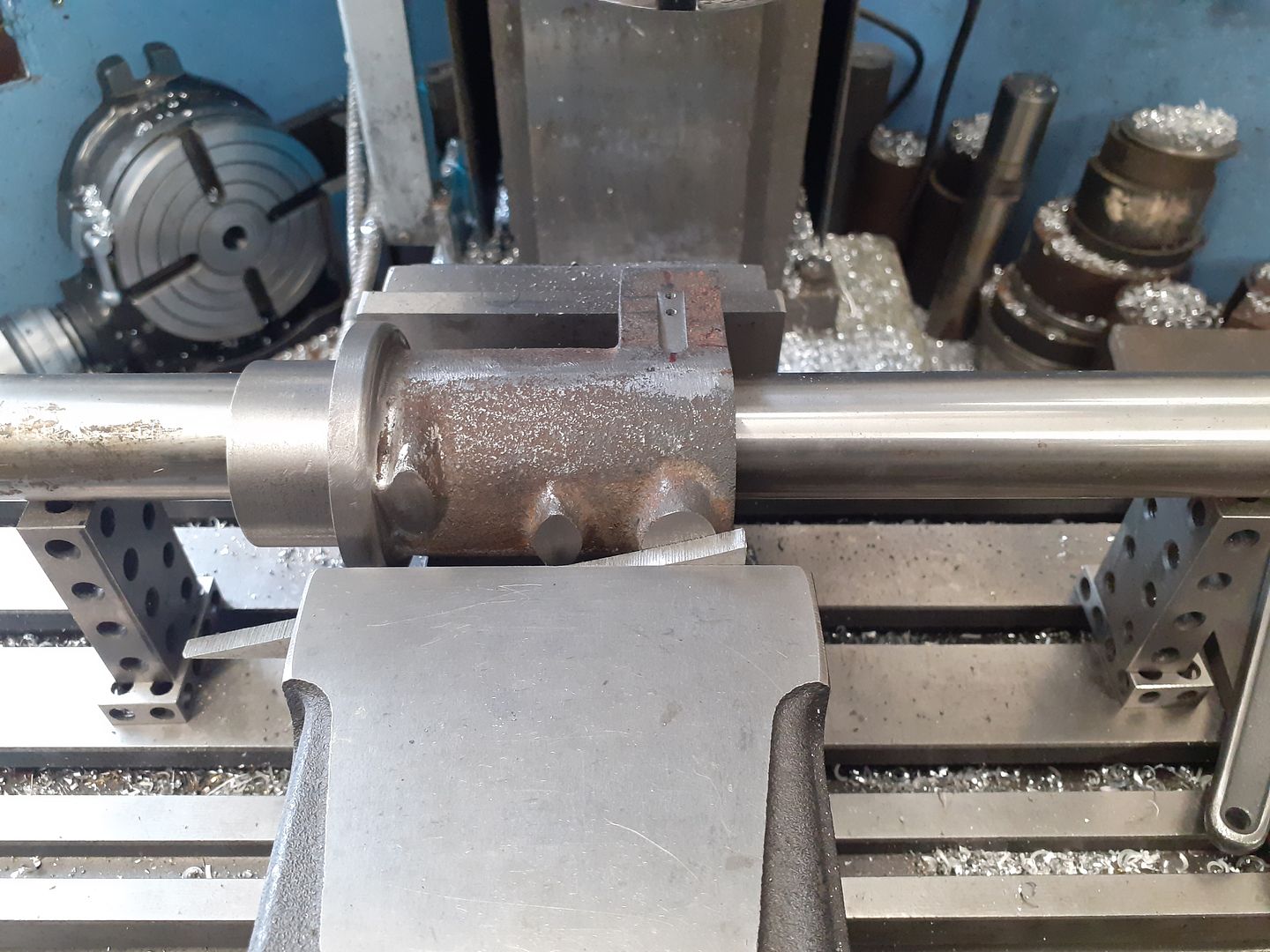
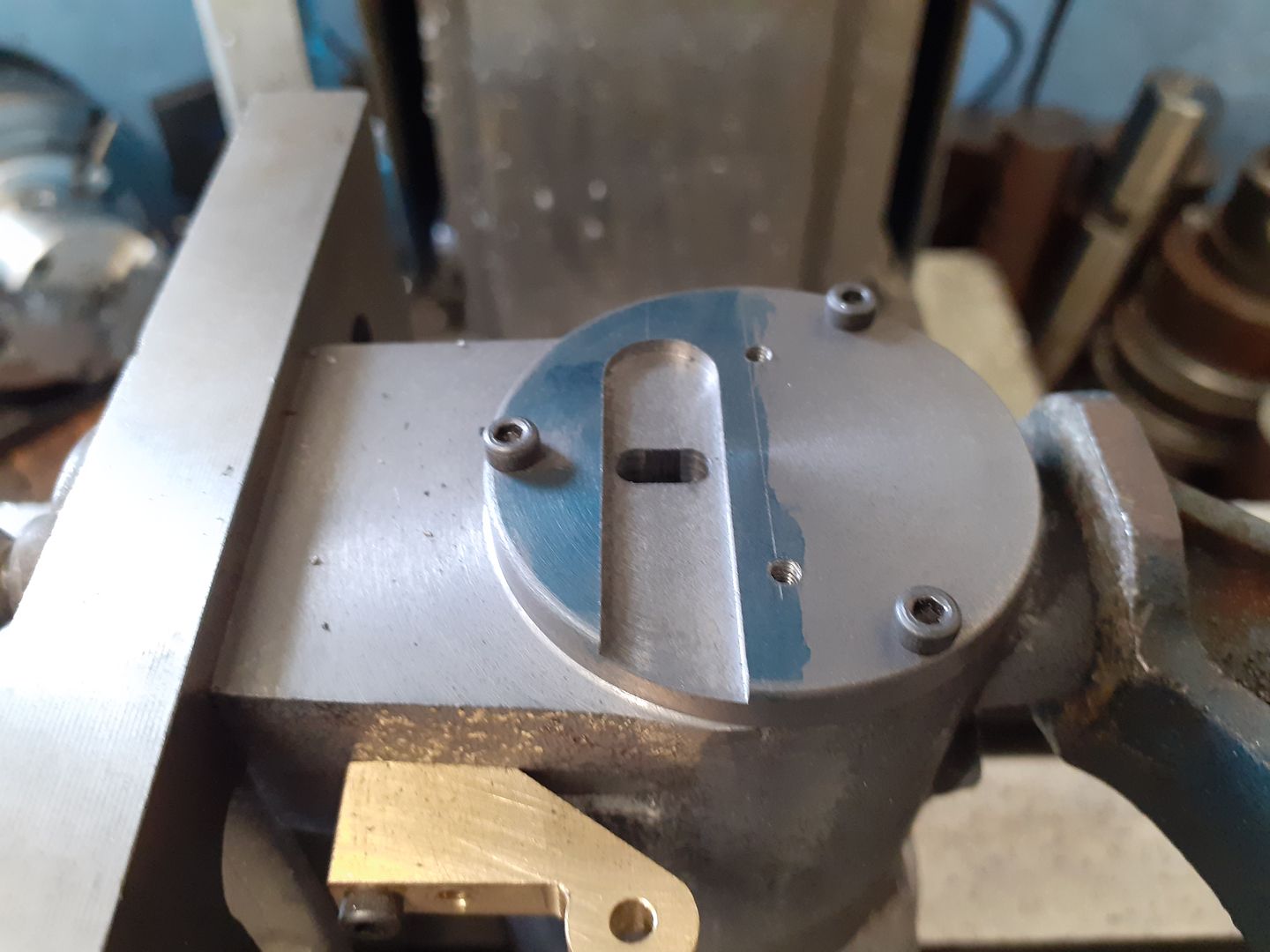
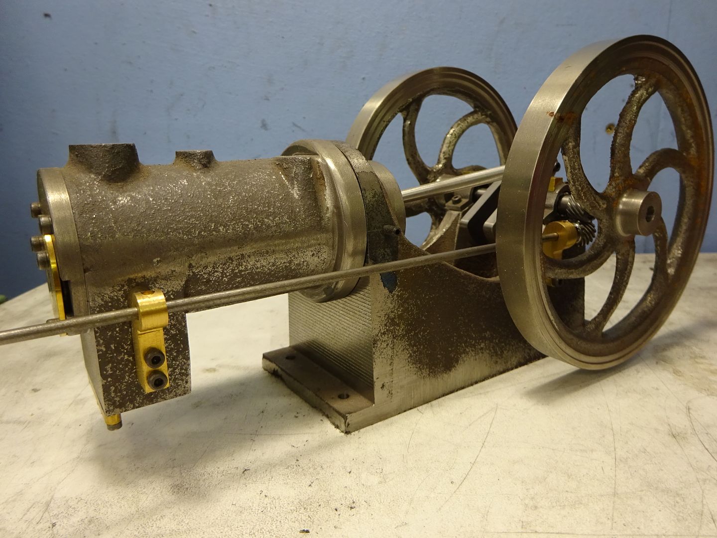
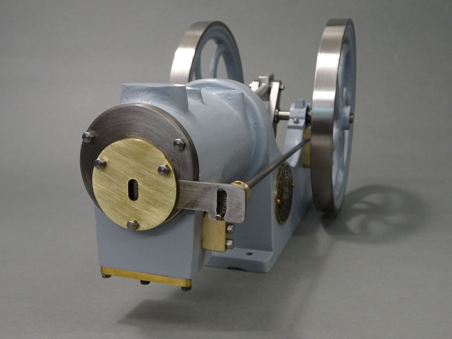
25215 forum posts 3105 photos 1 articles | The head was turned from some CI bar and then screwed onto the cylinder so that the slot for the shutter could be milled in the right orientation. The other two holes together with teh bottom one of the three head studs are to hold a brass disc that retains the shutter in it's slot. |
| Ady1 | 04/07/2023 19:49:03 |
 6137 forum posts 893 photos | Very nice Jason. As usual you make it look easy peasy Is it about 20KGs? |
| JasonB | 04/07/2023 20:35:26 |
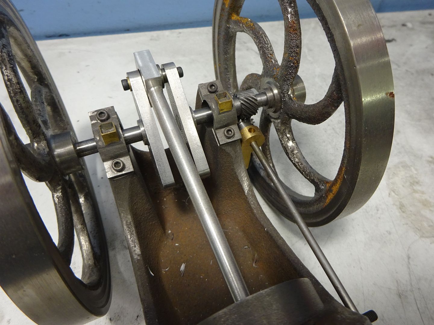
25215 forum posts 3105 photos 1 articles | Thanks Ady It's only a little one - 36mm bore 120mm flywheels, comes out about 4kg at the most |

Please login to post a reply.
Magazine Locator
Want the latest issue of Model Engineer or Model Engineers' Workshop? Use our magazine locator links to find your nearest stockist!
Sign up to our Newsletter
Sign up to our newsletter and get a free digital issue.
You can unsubscribe at anytime. View our privacy policy at www.mortons.co.uk/privacy
Latest Forum Posts
- *Oct 2023: FORUM MIGRATION TIMELINE*
05/10/2023 07:57:11 - Making ER11 collet chuck
05/10/2023 07:56:24 - What did you do today? 2023
05/10/2023 07:25:01 - Orrery
05/10/2023 06:00:41 - Wera hand-tools
05/10/2023 05:47:07 - New member
05/10/2023 04:40:11 - Problems with external pot on at1 vfd
05/10/2023 00:06:32 - Drain plug
04/10/2023 23:36:17 - digi phase converter for 10 machines.....
04/10/2023 23:13:48 - Winter Storage Of Locomotives
04/10/2023 21:02:11 - More Latest Posts...
- View All Topics
Support Our Partners


Shopping Partners
Subscription Offer

Latest "For Sale" Ads
- Reeves** - Rebuilt Royal Scot by Martin Evans
by John Broughton
£300.00 - BRITANNIA 5" GAUGE James Perrier
by Jon Seabright 1
£2,500.00 - Drill Grinder - for restoration
by Nigel Graham 2
£0.00 - WARCO WM18 MILLING MACHINE
by Alex Chudley
£1,200.00 - MYFORD SUPER 7 LATHE
by Alex Chudley
£2,000.00 - More "For Sale" Ads...
Latest "Wanted" Ads
- D1-3 backplate
by Michael Horley
Price Not Specified - fixed steady for a Colchester bantam mark1 800
by George Jervis
Price Not Specified - lbsc pansy
by JACK SIDEBOTHAM
Price Not Specified - Pratt Burnerd multifit chuck key.
by Tim Riome
Price Not Specified - BANDSAW BLADE WELDER
by HUGH
Price Not Specified - More "Wanted" Ads...
Get In Touch!
Do you want to contact the Model Engineer and Model Engineers' Workshop team?
You can contact us by phone, mail or email about the magazines including becoming a contributor, submitting reader's letters or making queries about articles. You can also get in touch about this website, advertising or other general issues.
Click THIS LINK for full contact details.
For subscription issues please see THIS LINK.
Digital Back Issues


Donate

 Register
 Log-in
Model Engineer Magazine
- Percival Marshall
- M.E. History
- LittleLEC
- M.E. Clock

ME Workshop
- An Adcock
- & Shipley
- Horizontal
- Mill

Subscribe Now
- Great savings
- Delivered to your door

Pre-order your copy!
- Delivered to your doorstep!
- Free UK delivery!
All Forum Topics > Stationary engines > Alyn Foundry Nattie #104