Using a Dividing head
| Tony Martins | 08/03/2023 11:32:04 |
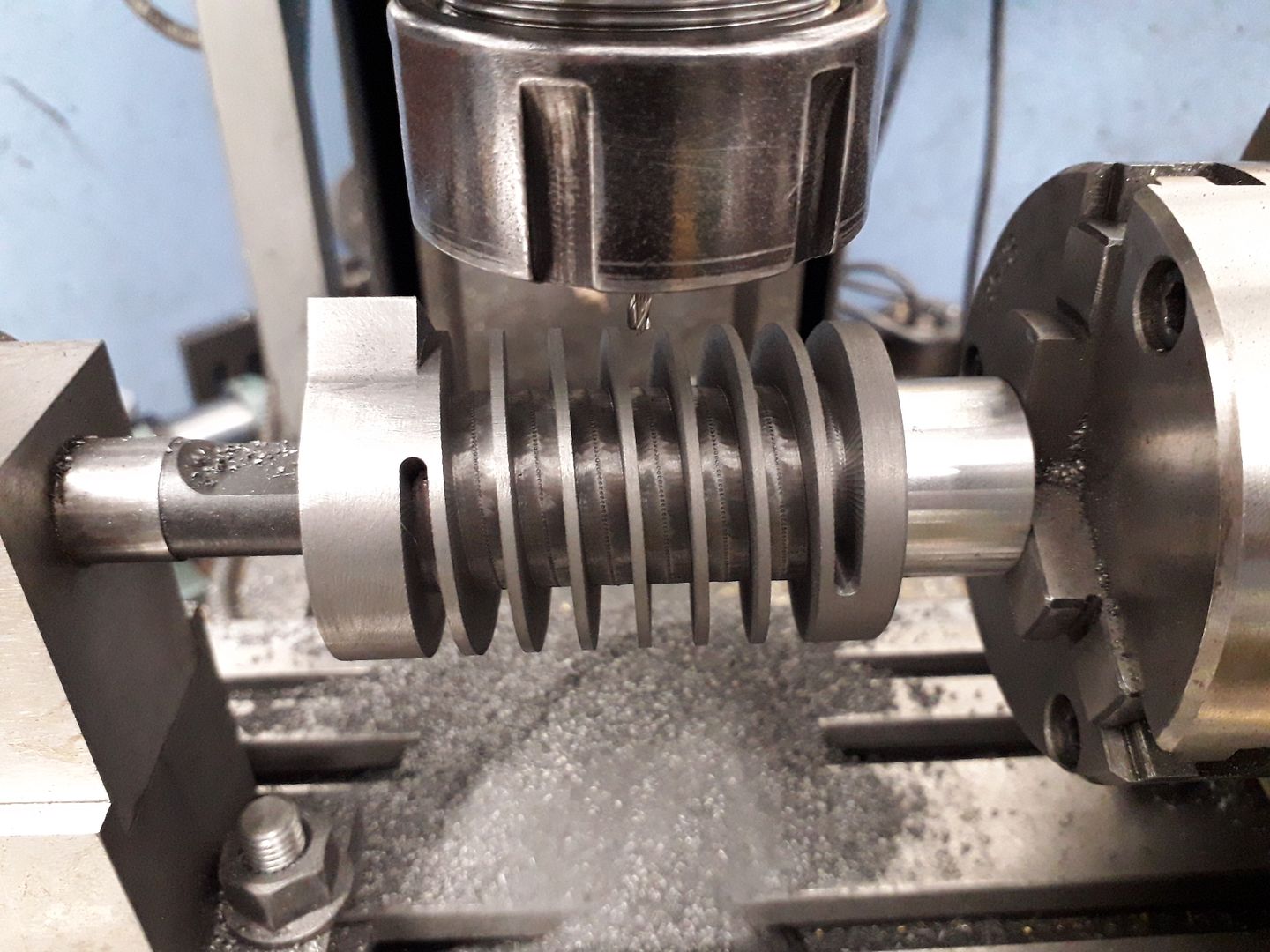
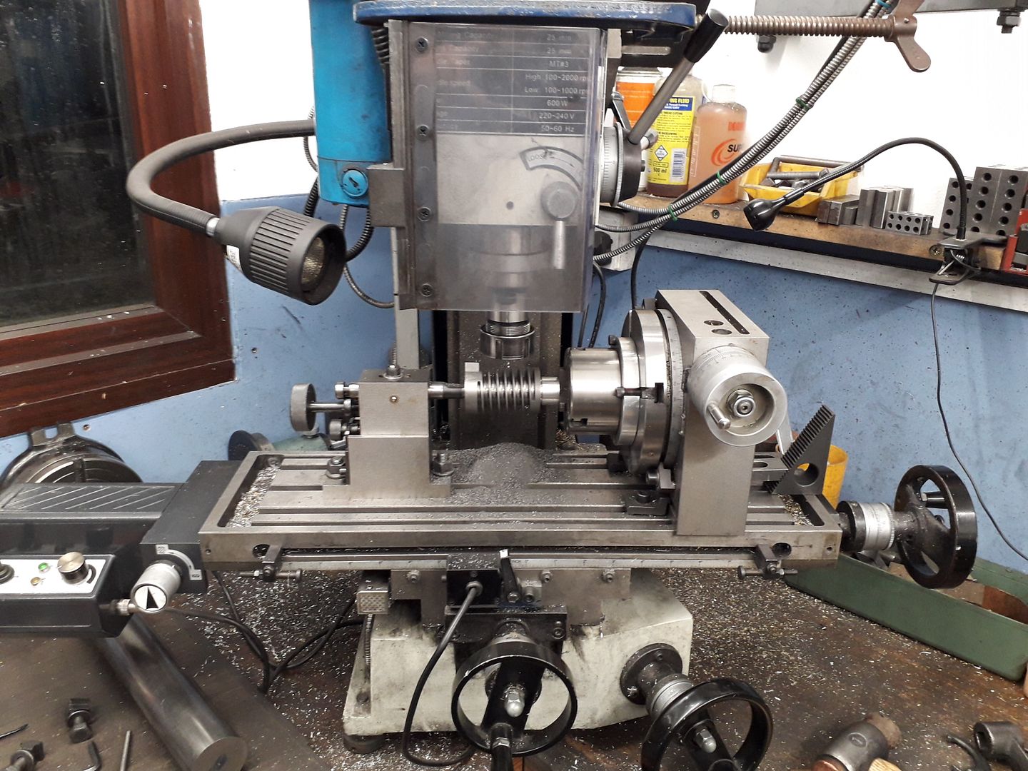
| 2 forum posts | Good morning all I have a need to machine a length of 1.5" dia x 1" TPI straight cut thread, my 1800 Student lathe is not man enough therefore I dreamed I may be able to use my indexing head on the mill and mill a spiral thread but as my indexing head is not a universal head I would like to know if it can easily be converted in some way to manually power the mill table by using a timing belt type drive or should I go back to sleep again. Any ideas will be much appreciated. Regards Tony ABM |
| JasonB | 08/03/2023 11:37:22 |
25215 forum posts 3105 photos 1 articles | Depends on how smooth the thread needs to be but it can simply be done in increments moving the table then rotating the work and depending on form you may need to make up a cutter.
I have seen other lash ups where the drive to the dividing head or rotary table was disengaged and various belts and pullies linked to the table handwheel so work turned when the table was moved which all seem to work OK and probably better than trying to drive the table from the dividing head Edited By JasonB on 08/03/2023 11:39:57 |
| John Haine | 08/03/2023 11:39:47 |
| 5563 forum posts 322 photos | Prof Chaddock recommended cutting the column thread for the Quorn using a powered milling spindle on the lathe carriage, and driving the headstock mandrel from the leadscrew using a handle on the leadscrew. |
| Martin Johnson 1 | 08/03/2023 12:45:50 |
| 320 forum posts 1 photos | Here is my set up for a steering box screw on a Tom Senior M1 and the usual Taiwan 6" rotary table: https://www.flickr.com/photos/140734312@N06/37334008234/in/album-72157669955074511/ Sorry dont know how to do a hyperlink. Martin Edited By JasonB on 08/03/2023 13:13:53 |
| Clive Foster | 08/03/2023 14:15:44 |
| 3630 forum posts 128 photos | Martin Cunning set up. Driving the rotary table directly via a chain of gears was, for me, a classic "D'oh obvious" now someone has shown me thing. Would work just as well with a spindexer too. Brilliant lateral thinking. Many professional dividing heads, like my Cincinnati copy Edgewick have a drive shaft provided for this sort of use. Cincinnati had whole bolt on change wheel bracket, gear set and cover assembly to use their heads on their mills. My dividing head came with couple of chain and sprocket assemblies that were used to connect it to a Bridgeport for, as I recall it, some sort of mould making work. Clive |
| John P | 08/03/2023 14:47:43 |
| 451 forum posts 268 photos |
I have done here almost the same as what you are trying to do at 1.480" dia |
| Clive Foster | 08/03/2023 16:56:41 |
| 3630 forum posts 128 photos | John P Martins method of directly driving a rotary table, spin-dexer or simple spindle seems much more appropriate than attempting to drive a dividing head via its normal worm and wheel. Direct 1:1 drive will replicate the feedscrew pitch. Coarser pitches will need the rotary drive stepped down in the same ratio as the feedscrew and desired pitch. So, for example, if the feedscrew is 8 tip and the desired pitch 1" then 8:1 step down will do the deed. It's unlikely that any ratio be large enough to be wildly impractical. Its the method I shall adopt should I ever need to do "figure 8" oiling grooves. Admittedly producing a metric pitch on an imperial machine or imperial pitch on a metric machine will be tricky as the conversion gear(s) need to be arranged. Arranging temporary metric or imperial feedscrew using decent studding might be more attractive in that case. As Y-axis feed will not be needed once all is set up an external screw is feasible with the nut clamped to the Y dovetails. Clive |
Please login to post a reply.
Want the latest issue of Model Engineer or Model Engineers' Workshop? Use our magazine locator links to find your nearest stockist!
Sign up to our newsletter and get a free digital issue.
You can unsubscribe at anytime. View our privacy policy at www.mortons.co.uk/privacy
- hemingway ball turner
04/07/2025 14:40:26 - *Oct 2023: FORUM MIGRATION TIMELINE*
05/10/2023 07:57:11 - Making ER11 collet chuck
05/10/2023 07:56:24 - What did you do today? 2023
05/10/2023 07:25:01 - Orrery
05/10/2023 06:00:41 - Wera hand-tools
05/10/2023 05:47:07 - New member
05/10/2023 04:40:11 - Problems with external pot on at1 vfd
05/10/2023 00:06:32 - Drain plug
04/10/2023 23:36:17 - digi phase converter for 10 machines.....
04/10/2023 23:13:48 - More Latest Posts...
- View All Topics
- Reeves** - Rebuilt Royal Scot by Martin Evans
by John Broughton
£300.00 - BRITANNIA 5" GAUGE James Perrier
by Jon Seabright 1
£2,500.00 - Drill Grinder - for restoration
by Nigel Graham 2
£0.00 - WARCO WM18 MILLING MACHINE
by Alex Chudley
£1,200.00 - MYFORD SUPER 7 LATHE
by Alex Chudley
£2,000.00 - More "For Sale" Ads...
- D1-3 backplate
by Michael Horley
Price Not Specified - fixed steady for a Colchester bantam mark1 800
by George Jervis
Price Not Specified - lbsc pansy
by JACK SIDEBOTHAM
Price Not Specified - Pratt Burnerd multifit chuck key.
by Tim Riome
Price Not Specified - BANDSAW BLADE WELDER
by HUGH
Price Not Specified - More "Wanted" Ads...
Do you want to contact the Model Engineer and Model Engineers' Workshop team?
You can contact us by phone, mail or email about the magazines including becoming a contributor, submitting reader's letters or making queries about articles. You can also get in touch about this website, advertising or other general issues.
Click THIS LINK for full contact details.
For subscription issues please see THIS LINK.
Model Engineer Magazine
- Percival Marshall
- M.E. History
- LittleLEC
- M.E. Clock
ME Workshop
- An Adcock
- & Shipley
- Horizontal
- Mill
Subscribe Now
- Great savings
- Delivered to your door
Pre-order your copy!
- Delivered to your doorstep!
- Free UK delivery!


 Register
 Log-in


