Forum sponsored by:

Help to identify make of rotary table and unusual lever.
| Keith Payne 1 | 12/02/2023 17:37:57 |
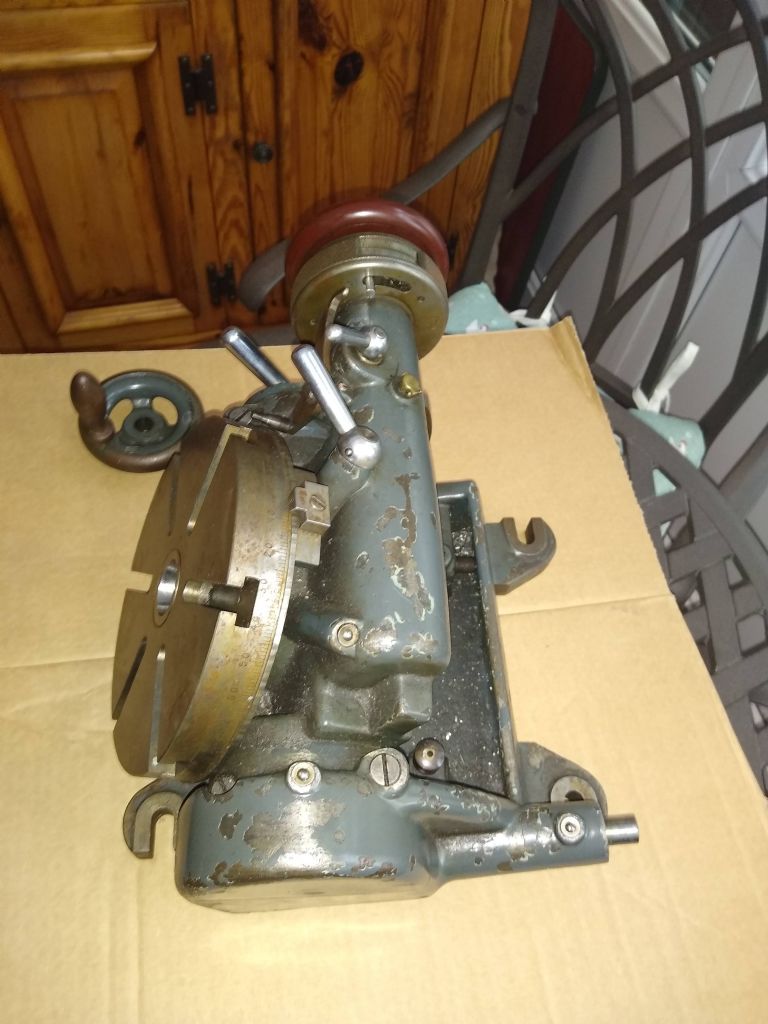
| 10 forum posts 7 photos | I have just bought this 5 inch tilting rotary table that does not have a makers name on it. It is really nicely made and feels very smooth when rotating it. It is a 90:1 ratio table with a 5 second vernier scale. The one thing that I have not seen before is the lever that pivots between the table and the scale. This is easily moved but I am not sure as to it's intended function. The table has small notches all around the circumference which the lever end locates in. I would be very gratifull if anyone knows the makers name and any idea as to the use for the lever. Many thanks for your help. |
| Nigel Graham 2 | 12/02/2023 22:23:06 |
| 3293 forum posts 112 photos | A fine find! I've not seen a rotary table like that but as you say the level's detent engages notches on the table, my first guess is this is some form of spin-indexing arrangement, used with the the worm-drive.disengaged. The fact that it also engages a pin on the scale is more puzzling. It might allow a dividing function, of sorts. The Vernier scale, 1-12, would I think give 5' of arc definition, not 5" as you suggest, if the main scale is in 1º steps. However, the table notches do not look very distinct at all, not enough to lock the table. They seem almost shallow enough to act as cams, and the lever is not ever so substantial, so does this arrangement actually drive the scale from rotating the table by hand, with its normal worm-gear disengaged? If so, it might give an angle measurement finer than the table scale - though that's a very elaborate way to do what would be possible with a Vernier scale on the table! Best thing really, is to place a big mug of tea, a pencil and notebook, next to the device on the table, and experiment with it manually to see what happens when you rotate things. Looking at it overall, I'd suggest the various handles: - lock the tilt function driven by the worm-shaft at the opposite end, - engage / disengage the table-driving worm to allow rapid positioning and spin-indexing or dividing. - lock the table itself. The lever nearest the hand-wheel seems to lock a plate having an elegantly curved "ear". That won't be ornament but it is hard to determine its purpose, unless it is a short lever to move the table worm in and out of engagement; once you've released its locking-lever.. . This looks to be a high-quality, high-precision tool that has had a busy life but in careful hands - no 'orrible 'oles in the table, etc. - perhaps in an instrument-making or a prototyping workshop; or on a large engraving-machine. Or had been used in a laboratory for aligning test-pieces or parts of the measuring-system in elevation and azimuth. Strange and rather sad that it has lost its name-plate though! As for restoring it fully, it does look very conveniently like Myford Grey! |
| Hopper | 12/02/2023 23:14:00 |
 7881 forum posts 397 photos | The lever looks like it interfaces with that pin sticking out the back of the handwheel/dial assembly. What does that pin do? |
| not done it yet | 13/02/2023 07:46:54 |
| 7517 forum posts 20 photos | Strange and rather sad that it has lost its name-plate though! As for restoring it fully, it does look very conveniently like Myford Grey! Somehow I doubt it. Did myford make anything with a table that large? Looks lie 6” centres in both directions for the fixing bolts. Certainly strange. Edited By not done it yet on 13/02/2023 07:47:32 |
| Martin Connelly | 13/02/2023 08:35:46 |
 2549 forum posts 235 photos | The lever looks like a brake to me that interacts with the rim of the table. The rim of the table looks like it has plenty of witness marks from the pressure. The lever behind the handwheel could be a brake on the handwheel. They do not look like they interact to me. Martin C Edited By Martin Connelly on 13/02/2023 08:38:28 Edited By Martin Connelly on 13/02/2023 08:40:14 |
| Nigel Graham 2 | 13/02/2023 09:07:08 |
| 3293 forum posts 112 photos | NDIY- I did not say it may have been made by Myford, at all. I'd commented the colour is conveniently close to one available for Myford machines. . Martin - Stop-blocks? I don't see those on this specimen at all, but I would not expect them to mark the table. Stop-blocks on rotary-tables are normally similar to those on milling-machine tables: clamped in a T-slot round the rim, and acting on a fixed point alongside it. The little indentations that apparently engage the pin on the lever don't appear sufficient for the purpose, but might be part of an indexing function that also uses the pin enquired of by Hopper.. . My approach would simply be as I'd suggested: sit down at the table with it, and try gently operating its various functions and controls. Doing that, everything should soon become clear. The lack of brand might arise from it being originally a normal, standard part of something much larger, so the maker would not have thought its own label necessary.. ' Keith - Please do analyse it, and put all our minds at rest by describing it!
|
| Keith Payne 1 | 13/02/2023 11:44:08 |
| 10 forum posts 7 photos | Thanks for all the replies. I am going to look into it more so plenty of tea at the ready. The idents around the table are equally spaced and all the same depth. They seem to be indexing as has been suggested rather that locks. It came from a one off , prototype toolroom that is unfortunately closing due to the increase in fuel costs. They equipment they have is mainly German but this is a lot older than the current machines. I remember when I was working in the proto shop, we had all sorts of wonderful bits of equipment which, if part of a makers accessory kit, did not always carry the makers name. This would make sense here. I will get on with measuring and report back. Thanks again. |
| Martin Connelly | 13/02/2023 13:01:31 |
2549 forum posts 235 photos | Nigel, I edited out the stop blocks comment just after I had written it, I realised it was the index mark at the top when returning to the pictures. I did this quite rapidly but you managed to spot this error and commented after the correction was made. Martin |
| Bazyle | 13/02/2023 13:38:11 |
 6956 forum posts 229 photos | So what are the angles that have indents and how much does the far end of the lever move as it drops into the indent. there seems to be a spigot next to the end of the lever that moves in a slot. What does it do? If nothing then perhaps it is to hold an item that is moved by the lever such as a counter that helps keep track of the position eg every ten degrees. |
| Keith Payne 1 | 13/02/2023 15:58:41 |
| 10 forum posts 7 photos | Hi all. I have been in touch with the toolroom i bought it from and was told they think it is a Hauser in Switzerland. They made jig borers as well as other precision instruments and eventually joined as part of S.I.P. group. I have been checking this and it matches the type used on their earlier jig borers. I have managed to find parts of a manual for a larger table and this solves the riddle of the lever and marks around the table. It was made as a very high precision table with worm gear correction. The lever touches both the circumference of the table and a bar which extends from the back of the vernier scale. The vernier is spring loaded and in constant contact with the lever and therefore the table. As the table rotates, the vernier is moved slightly back and forth by the lever which responds to the depths of scrapped cutouts on the table circumference. This system is called a compensation lever and compensates for slight imperfections of the worm screw driving the table. It was used on the Hauser and SIP jig borers and therefore the table was likely part of a jig boring kit and have no individual makers name on it. I have attached a section of the manual which describes what I mean.
This is very new to me and thank everyone for their help. I intend to strip and clean the table and will document this as I go along. |
| Nigel Graham 2 | 13/02/2023 16:13:55 |
| 3293 forum posts 112 photos | Thank you Keith, For rescuing the table, and for discovering and telling us what it all does! |
| old mart | 13/02/2023 18:45:45 |
| 4655 forum posts 304 photos | I looked on Lathes UK at Hauser and their rotary tables and couldn't find a match. Too many differences between the 160mm and your 6". |
| Michael Gilligan | 13/02/2023 18:56:01 |
 23121 forum posts 1360 photos | Great result, Keith Isn’t it good to see that the people who really know about this stuff admit to the fact that there are inevitable imperfections. MichaelG. |
| Keith Payne 1 | 17/02/2023 12:40:17 |
| 10 forum posts 7 photos | Just a quick update. The Hauser rotary table uses W20 collets also known as schaublin collets. I bought one and tried it today . The w20 collet is a perfect fit to the table so further confirms the tables identity. Thanks for all the help and interest in this table. |
| Colin Heseltine | 17/02/2023 22:20:45 |
| 744 forum posts 375 photos | Keith, I am intrigued by your comment regarding W20 collets fitting the RT. I have the large Hauser RT that you have shown in the photocopied page above. Do the collets fit directly in the central bore. If so how are they pulled tight. Colin |
| Hopper | 18/02/2023 03:59:29 |
7881 forum posts 397 photos | Thanks for reporting back on what that lever is for. Quite intriguing. |
| Keith Payne 1 | 18/02/2023 12:12:08 |
| 10 forum posts 7 photos | Hi Colin, The collet pushes directly in the centre opening. It is clear through to the back and appears to possible be draw in by a suitable drawbar. I would think that this would be easy to make for when the table is orientated vertically but need to look in to whether there is enough room underneath when the table is horizontal. I have just ordered a w20 to M.T.1 conversion sleeve from Luxembourg. with a few to making a Morse taper centering ball piece for when the table is tilted. I will be cleaning and servicing the table so will hopefully get a better understanding of the way it works. It is extremely well made and uses high quality materials. If anyone has a Hauser table manual that is available to copy , I would be grateful if you could please get in touch. I intend to investigate making a drawbar for the table and will let you know how I get on.
|
| Michael Gilligan | 18/02/2023 14:58:27 |
23121 forum posts 1360 photos | You may find this useful, Keith .
. MichaelG. |
| Keith Payne 1 | 18/02/2023 16:21:39 |
| 10 forum posts 7 photos | Hi Michael, Thank you so much for that information. I can use this when grinding the threading cutter. It is interesting that it seems to equate to a 15 TPI thread which I think was a buttress thread as shown by the American Walter company hence the W designation. I will design a short drawbar with maybe a pin wheel type of end diameter to allow for tightening of the collet without too much stick out from the table. I always enjoy the way one thing leads to another in the matching world. Thanks for your help.
|
| Adam Harris | 18/02/2023 21:05:28 |
| 533 forum posts 26 photos | Keith, I do have the 6" Hauser tilting rotary table from the 70's / 80's and there are far too many design differences between mine and yours in my opinion for yours to be an earlier "rounder" version. One difference which is obviously superior (ie unlikely to be on an earlier version) is that your tilt rack is covered whereas mine is open and exposed to swarf. Edited By Adam Harris on 18/02/2023 21:07:22 |


Please login to post a reply.
Magazine Locator
Want the latest issue of Model Engineer or Model Engineers' Workshop? Use our magazine locator links to find your nearest stockist!
Sign up to our Newsletter
Sign up to our newsletter and get a free digital issue.
You can unsubscribe at anytime. View our privacy policy at www.mortons.co.uk/privacy
Latest Forum Posts
- *Oct 2023: FORUM MIGRATION TIMELINE*
05/10/2023 07:57:11 - Making ER11 collet chuck
05/10/2023 07:56:24 - What did you do today? 2023
05/10/2023 07:25:01 - Orrery
05/10/2023 06:00:41 - Wera hand-tools
05/10/2023 05:47:07 - New member
05/10/2023 04:40:11 - Problems with external pot on at1 vfd
05/10/2023 00:06:32 - Drain plug
04/10/2023 23:36:17 - digi phase converter for 10 machines.....
04/10/2023 23:13:48 - Winter Storage Of Locomotives
04/10/2023 21:02:11 - More Latest Posts...
- View All Topics
Support Our Partners


Shopping Partners
Subscription Offer

Latest "For Sale" Ads
- Reeves** - Rebuilt Royal Scot by Martin Evans
by John Broughton
£300.00 - BRITANNIA 5" GAUGE James Perrier
by Jon Seabright 1
£2,500.00 - Drill Grinder - for restoration
by Nigel Graham 2
£0.00 - WARCO WM18 MILLING MACHINE
by Alex Chudley
£1,200.00 - MYFORD SUPER 7 LATHE
by Alex Chudley
£2,000.00 - More "For Sale" Ads...
Latest "Wanted" Ads
- D1-3 backplate
by Michael Horley
Price Not Specified - fixed steady for a Colchester bantam mark1 800
by George Jervis
Price Not Specified - lbsc pansy
by JACK SIDEBOTHAM
Price Not Specified - Pratt Burnerd multifit chuck key.
by Tim Riome
Price Not Specified - BANDSAW BLADE WELDER
by HUGH
Price Not Specified - More "Wanted" Ads...
Get In Touch!
Do you want to contact the Model Engineer and Model Engineers' Workshop team?
You can contact us by phone, mail or email about the magazines including becoming a contributor, submitting reader's letters or making queries about articles. You can also get in touch about this website, advertising or other general issues.
Click THIS LINK for full contact details.
For subscription issues please see THIS LINK.
Digital Back Issues


Donate

 Register
 Log-in
Model Engineer Magazine
- Percival Marshall
- M.E. History
- LittleLEC
- M.E. Clock

ME Workshop
- An Adcock
- & Shipley
- Horizontal
- Mill

Subscribe Now
- Great savings
- Delivered to your door

Pre-order your copy!
- Delivered to your doorstep!
- Free UK delivery!
All Forum Topics > Workshop Tools and Tooling > Help to identify make of rotary table and unusual lever.