Forum sponsored by:

Experimental Pendulum Clock
| SillyOldDuffer | 27/11/2022 19:57:07 |
| 10668 forum posts 2415 photos | Ages ago I built a pendulum clock with a bob on the end of a short thin carbon rod with no suspension, the idea being that the rod would act as a spring that's not temperature sensitive. Didn't keep good time, partly because the rod tends to swing in an ellipse, with low Q, and partly because it's sensitive to humidity. (I guess the plastic matrix is effected and humidity alters it's springiness, nothing to do with the fibre.) Bit of reinventing the wheel because I can't find the notes describing where I'd got to, but I've made a start by adding a suspension:
Zooming in on the suspension, I'd welcome comments on the design:
The spring, 0.1mm thick, is cut from the blade of a disposable razor, edge blunted to avoid spilling blood. It's clamped between brass cheeks, with about 2mm free to flex. The 0.8mm diameter carbon fibre rod is superglued into the cone, which is 10mm long. Is this a good design? The results are odd. The graph is a run of about 25 hours,
The top graph shows tick times vary and that the variation is slowly getting worse. A perfect pendulum would graph as a straight line. Worse than expected; the average tick is 13369412 Arduino Clock Cycles, which has a 16MHz quartz crystal, actually averaging 15998101Hz. However the fastest tick took 13275269 cycles, and the slowest 13471208. The range is 195939 cycles, about 0.012s, which I feel is too much. The second graph is a moving average of the first. It shows that the pendulum is gradually speeding up, and its not related to temperature, air pressure or humidity. Most confusing is the third graph, which is the wrong shape! It counts the number of beats in each of 20 buckets across the range of variation and shows the slow and fast tick counts, both outnumber the average. I'd expect the distribution to be concentrated in buckets closest to the average. Instead, the graph implies the pendulum has two modes of oscillation. Any ideas what might cause a pendulum to display these symptoms? Dave
|
| Andrew Johnston | 27/11/2022 20:35:13 |
 7061 forum posts 719 photos | How do you know that the Arduino Clock Cycle is accurate and stable? A quartz crystal probably won't vary enough to give the results seen. But they do drift, usually 50 to 100ppm at the lower cost end. Stability is also dependent on the quality of the oscillator. Presumably there is softare between the crystal oscillator and the measurement being made? Andrew |
| Robert Atkinson 2 | 27/11/2022 21:08:34 |
 1891 forum posts 37 photos | Apart from Andrews comments re the reference, if this is the first period of running, could it be due to changes in the flexture? Either work hardening or fatigue. I guess use as a pendulum flexture was not on the razor designers mind when the chose the steel for the blade. On references, how do you know the Arduino crystal is 15.998101 MHz? The crystals used for microcotrollers are not known for their accuracy. Robert G8RPI. |
| Michael Gilligan | 27/11/2022 21:46:14 |
 23121 forum posts 1360 photos | Instinct says that your spring is too short an too thick, Dave … I think that you might find the rod is taking some of the bending. As a quick check … try clamping a few strands of silk thread [or some-such] between the cheeks instead of the razor blade. MichaelG. |
| duncan webster | 28/11/2022 00:35:31 |
| 5307 forum posts 83 photos | Many moons ago, razor blades were the go to source for suspension springs for home made clocks. These would have been the old carbon steel ones. I used some 0.004" stuff I got from who knows where. Not stainless but too hard to drill, had to punch it. Humidity has 2 effects apart from any material effects, firstly it makes the air less dense, so it reduces buoyancy, effectively increasing g. Second less dense air will have lower drag. I was advised by a BHI chap to make my suspension spring 'no more than 10 mm'. I know 2mm is not more than 10, but it's at the other end of the spectrum. All depends on angle of swing I suppose. How constant is that? Edited By duncan webster on 28/11/2022 00:36:22 |
| John Haine | 28/11/2022 08:10:14 |
| 5563 forum posts 322 photos | Does your illustration show the full cheek arrangement or is it missing the clamping part? |
| SillyOldDuffer | 28/11/2022 09:39:08 |
| 10668 forum posts 2415 photos | Posted by John Haine on 28/11/2022 08:10:14:
Does your illustration show the full cheek arrangement or is it missing the clamping part? Easy question first: to show the construction I left the clamps out of the illustration. In complete form it looks like this:
The clamps are threaded M2, and each is pulled against the body by single M2 screw passing through the square holes fortuitously added to the razor blade by the manufacturer. A few more construction details, because the whole thing is novel. The free-standing clock is less than 300mm high and the pendulum frame is a tripod made of aluminium tubing braced by M4 studding. I assume it's proportionally rigid compared to the small bob:
The structure is sized to fit inside a length of drainpipe and evacuated so the bob swings in a good vacuum. The feature is built but not tested because the pendulums performance so far isn't good enough to justify pumping the air out.
And a shot of the actual suspension:
Dave Edit Ooops. Fixed the photos, thanks Michael! Edited By SillyOldDuffer on 28/11/2022 10:09:11 |
| Michael Gilligan | 28/11/2022 10:00:06 |
23121 forum posts 1360 photos | You need a Moderator to rotate those photos, Dave
MichaelG. |
| SillyOldDuffer | 28/11/2022 10:08:14 |
| 10668 forum posts 2415 photos | Posted by Michael Gilligan on 27/11/2022 21:46:14:
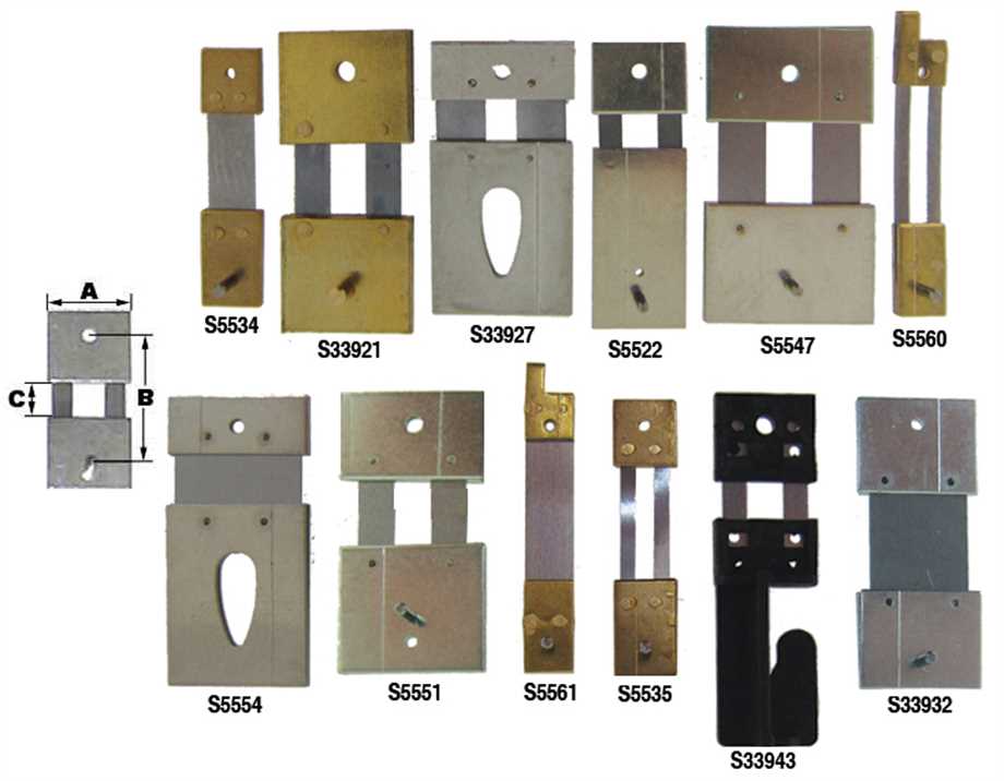
Instinct says that your spring is too short an too thick, Dave … I think that you might find the rod is taking some of the bending. As a quick check … try clamping a few strands of silk thread [or some-such] between the cheeks instead of the razor blade. MichaelG. My worry too. I need to re-read my books because my memory is terrible, but I don't recall any of them discussing the optimum length or strength of a suspension spring. I assumed the spring should simply be strong enough to support the weight of the bob, and noted that spares sold for big clocks mostly look short compared with their pendula. (Pic from Cousins) I was also keen to reduce the amount of temperature sensitive metal in the pendulum by not exposing more spring than necessary.
I haven't attempted to measure Q yet. If a 0.1mm ( 0.004" ) razor blade is too thick, I could sand it down. Should be easy enough to Dremel out a slot as well. My authorities aren't keen on silk suspensions in high performance clocks, I guess because threads don't resist twisting as well as a blade spring. The more I get into clocks the more I find I don't understand. Beyond simply lightening the spring, does anyone know what needs to be done to optimise a pendulum spring suspension? Dave Edited By SillyOldDuffer on 28/11/2022 10:09:59 |
| Robert Atkinson 2 | 28/11/2022 10:11:43 |
1891 forum posts 37 photos | I hope you are not testing it sat on the windowsill..... |
| Michael Gilligan | 28/11/2022 10:20:55 |
23121 forum posts 1360 photos | Posted by SillyOldDuffer on 28/11/2022 10:08:14:
[…]
My authorities aren't keen on silk suspensions in high performance clocks,
. Did you notice that I used the words “As a quick check …” Dave ? Also [with the greatest respect] … You don’t currently have a high performance clock there. MichaelG. |
| Bazyle | 28/11/2022 10:34:57 |
 6956 forum posts 229 photos | I'm not an Arduino user recently so don't know how you might be measuring period but are you using a RTOS mode and if it is saving or outputting results how does it do that without affecting the measurement. The existence of two period peaks implies one with and one without an extra interrupt routine. Bit like the LinuCNC timing problem on unsuitable computers. |
| Michael Gilligan | 28/11/2022 10:37:06 |
23121 forum posts 1360 photos |
. This crams a lot of good stuff into its 145 pages MichaelG. |
| SillyOldDuffer | 28/11/2022 11:55:53 |
| 10668 forum posts 2415 photos | Posted by Andrew Johnston on 27/11/2022 20:35:13:
How do you know that the Arduino Clock Cycle is accurate and stable? A quartz crystal probably won't vary enough to give the results seen. But they do drift, usually 50 to 100ppm at the lower cost end. Stability is also dependent on the quality of the oscillator. Presumably there is softare between the crystal oscillator and the measurement being made? AND Apart from Andrews comments re the reference, if this is the first period of running, could it be due to changes in the flexture? Either work hardening or fatigue. I guess use as a pendulum flexture was not on the razor designers mind when the chose the steel for the blade. On references, how do you know the Arduino crystal is 15.998101 MHz? The crystals used for microcotrollers are not known for their accuracy. Robert G8RPI. Good questions. The microcontroller is a Sparkfun Pro Micro, a miniaturised version of an Arduino Leonardo. It comes with a quartz crystal rather than a cheap unstable ceramic resonator. However, the crystal is an ordinary 50 - 100ppm type, there's no capacitor, and I've made no attempt to stabilise the temperature. The microcontroller measures the number of crystal ticks per swing and for best resolution this is mostly done in hardware. The 16MHz system clock feeds a hardware counter triggered on/off by the pendulum blocking an IR beam. The counter is zero at start and on overflow, it clocks another counter. When the off signal is received both counters are frozen and a simple sum gives the total number of crystal pulses per swing. As the counters run at 16MHz, the pendulum is measured in ticks of about 0.0625 microseconds, considerably better than doing the same in software (worse than 4 microsecond resolution.) Accuracy depends on the quartz crystal, which of course could be wrong by 100 parts per million, and is temperature sensitive. The same counter technique can be used to measure the actual frequency of the crystal. Substituting the seconds pulse output of a GPS module for the pendulum, the microcontroller counts the number of oscillations made in one second. This can be repeated and averaged. In the clock, during the 0.8s between swings, environmental data is read, and everything logged to a Raspberry Pi3B. The data is: 13432949 0.7461 200 0 994.76 81.29 14.87 836040 1669630663 148802507 Tick Count - 13432949 In the current set up I'm measuring the crystal's average frequency by comparing it with Network Time. The Raspberry Pi3B is connected to the internet and synchronises using NTP every 38 minutes. It timestamps log data on receipt, making it possible to compare pendulum clock time with network time, but otherwise has little else to do that might interfere. The arrangement isn't brilliant, but the Pi3B's notion of time is always better than 0.1s accurate, making it suitable for long-term comparisons. The number of crystal ticks counted over several accurate hours gives the frequency. I should also analyse the data by time slots, to see how the average frequency alters hour by hour. Until this morning, results suggested the experimental clock wasn't sensitive to the environment, but today suggests it could be tracking air-pressure. In the graphs below, the moving average falls with the millibar line until this morning when both lift together. Far from conclusive! I need to let the clock run for a lot longer. I'm flummoxed by the shape of the 'Ticks by Bucket' graph. Next job is to check my code for the fifth time! Maybe I've misunderstood matplotlib or messed up the analysis. Otherwise I can't imagine how a pendulum's period could vary like that. Robert's point about this being the first period of running is good. Although the clock has been run several times to test it and the software, they were all short runs. This is the first long one and perhaps it's shaking down. If so, it's taking a long time! Let Robert's confession to being a 'time-nut' be a dire warning to others. The pursuit of accuracy time is addictive. I'm wasting lots of time on this and lust after Rubidium too... Dave |
| SillyOldDuffer | 28/11/2022 11:57:54 |
| 10668 forum posts 2415 photos | Posted by Michael Gilligan on 28/11/2022 10:20:55:
Posted by SillyOldDuffer on 28/11/2022 10:08:14:
[…]
My authorities aren't keen on silk suspensions in high performance clocks,
. Also [with the greatest respect] … You don’t currently have a high performance clock there. MichaelG. I know, that's the problem...
|
| SillyOldDuffer | 28/11/2022 12:04:34 |
| 10668 forum posts 2415 photos | Posted by Robert Atkinson 2 on 28/11/2022 10:11:43:
I hope you are not testing it sat on the windowsill..... Guilty. It's in an unoccupied north facing bedroom, and mostly safe from the cat. Where's the best place in an ordinary semi for a sensitive clock? Under stairs? Dave
|
| Peter Cook 6 | 28/11/2022 12:31:01 |
| 462 forum posts 113 photos | Dave, One way a pendulum could appear to behave like that is if it is slightly off vertical (out of beat), and you were comparing the timing of the left-right swing with the right-left swing. Looking at the numbers (0.86sec period = about 180mm pendulum length), it seems that you are correctly counting full cycles, i.e. left-right-left. If you are, then you need to drop the next left-right transition before starting the cycle again otherwise your system or code could be alternately timing left-right-left, and right-left-right which could give you the results you are getting. PS a second thought - could the pendulum with its spring and flexible rod be behaving as a double pendulum. They do weird things! In regular clocks the pendulum rod is very rigid compared to the suspension spring. Sorry my math is not up to analysing a double pendulum.
Edited By Peter Cook 6 on 28/11/2022 13:52:35 |
| Peter Cook 6 | 28/11/2022 15:24:16 |
| 462 forum posts 113 photos | Dave - sorry - I got myself confused between positions and transitions - but the idea of the pendulum being out of beat stands. |
| SillyOldDuffer | 28/11/2022 15:35:01 |
| 10668 forum posts 2415 photos | Posted by Peter Cook 6 on 28/11/2022 15:24:16:
Dave - sorry - I got myself confused between positions and transitions - but the idea of the pendulum being out of beat stands. Best suggestion yet! I need to look at the program to see if it's possible, and if so what to do about it. Just back from a hospital visit and found there was a power cut whilst I was out. My plan to let the clock run for a few more days has crashed and burned. Never mind, it's an opportunity to move the clock off the windowsill and tweak the code again. Maybe I should install battery backup too! Dave |
| jaCK Hobson | 28/11/2022 16:25:57 |
| 383 forum posts 101 photos | How is the pendulum support located? There seems to be a correlation between pressure and period - so try sucking the air out. The perfect pendulum doesn't involve a spring at all. Any hint of a spring gets it further from perfect doesn't it? You want the suspension to be very much stiffer in every direction other than where you want it to swing. And not stiff at all in the direction of swing. Thinner section, but wider suspension. You can get very good time keeping by having a mechanism to adjust for air differences rather than trying to eliminate the air. But I can see eliminating air is a fun project. I think you should get a better RTC. I think you can get much better ones that the arduino for peanuts. |


Please login to post a reply.
Magazine Locator
Want the latest issue of Model Engineer or Model Engineers' Workshop? Use our magazine locator links to find your nearest stockist!
Sign up to our Newsletter
Sign up to our newsletter and get a free digital issue.
You can unsubscribe at anytime. View our privacy policy at www.mortons.co.uk/privacy
Latest Forum Posts
- *Oct 2023: FORUM MIGRATION TIMELINE*
05/10/2023 07:57:11 - Making ER11 collet chuck
05/10/2023 07:56:24 - What did you do today? 2023
05/10/2023 07:25:01 - Orrery
05/10/2023 06:00:41 - Wera hand-tools
05/10/2023 05:47:07 - New member
05/10/2023 04:40:11 - Problems with external pot on at1 vfd
05/10/2023 00:06:32 - Drain plug
04/10/2023 23:36:17 - digi phase converter for 10 machines.....
04/10/2023 23:13:48 - Winter Storage Of Locomotives
04/10/2023 21:02:11 - More Latest Posts...
- View All Topics
Support Our Partners


Shopping Partners
Subscription Offer

Latest "For Sale" Ads
- Reeves** - Rebuilt Royal Scot by Martin Evans
by John Broughton
£300.00 - BRITANNIA 5" GAUGE James Perrier
by Jon Seabright 1
£2,500.00 - Drill Grinder - for restoration
by Nigel Graham 2
£0.00 - WARCO WM18 MILLING MACHINE
by Alex Chudley
£1,200.00 - MYFORD SUPER 7 LATHE
by Alex Chudley
£2,000.00 - More "For Sale" Ads...
Latest "Wanted" Ads
- D1-3 backplate
by Michael Horley
Price Not Specified - fixed steady for a Colchester bantam mark1 800
by George Jervis
Price Not Specified - lbsc pansy
by JACK SIDEBOTHAM
Price Not Specified - Pratt Burnerd multifit chuck key.
by Tim Riome
Price Not Specified - BANDSAW BLADE WELDER
by HUGH
Price Not Specified - More "Wanted" Ads...
Get In Touch!
Do you want to contact the Model Engineer and Model Engineers' Workshop team?
You can contact us by phone, mail or email about the magazines including becoming a contributor, submitting reader's letters or making queries about articles. You can also get in touch about this website, advertising or other general issues.
Click THIS LINK for full contact details.
For subscription issues please see THIS LINK.
Digital Back Issues


Donate

 Register
 Log-in
Model Engineer Magazine
- Percival Marshall
- M.E. History
- LittleLEC
- M.E. Clock

ME Workshop
- An Adcock
- & Shipley
- Horizontal
- Mill

Subscribe Now
- Great savings
- Delivered to your door

Pre-order your copy!
- Delivered to your doorstep!
- Free UK delivery!
All Forum Topics > Clocks and Scientific Instruments > Experimental Pendulum Clock