Forum sponsored by:

A Lightweight Husky
| JasonB | 03/12/2021 16:47:07 |
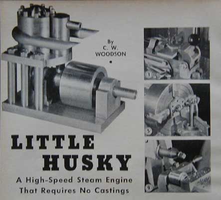
 25215 forum posts 3105 photos 1 articles | Having recently enjoyed making the Gamages and Bassett Lowke small marine steam engines the next engine to catch my eye while looking for something else was C W Woodson's "Little Husky" as it was a similar type engine and being a Uniflow would allow me to tick off making one of those too. It also had those tempting words "Requires no Castings"
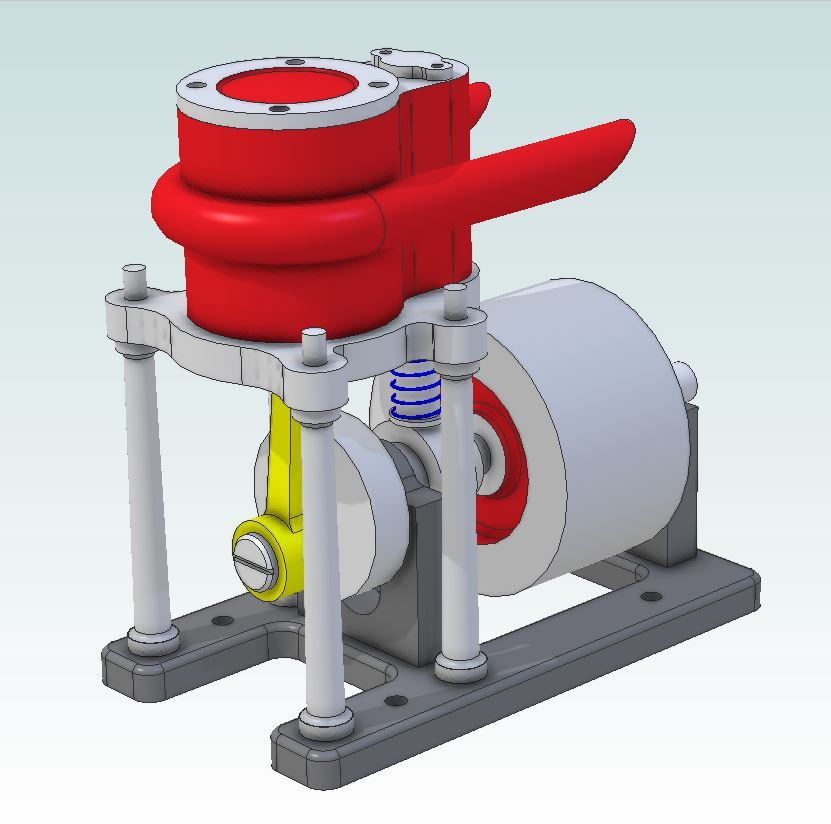
The original article appeared in Popular Science Magazine in 1944 and can be read here There have been a few of these built on the various forums and even Julius has done a version but they all looked a bit heavy and bulky to my eye. So as well as redrawing it in metric I set about putting this little puppy on a diet and adding a few curves and features while I was at it. The main areas of attention are: - Entablature and Base. Both made of thinner material and some additional machining to remove excess metal and add some shape particularly to the entablature and I also added some holes so it could be mounted in a hull if needed. - Columns. Reduced in number from six to four, smaller diameter and also a bit taller with a tapered profile rather than just straight bar. - Bearing Supports. A couple of holes to reduce bulk and separate bronze bearings added - Cylinder / Valve chest. Rather than solder two cylinders together I cut this from solid. The valve hole was reamed right through rather than try and ream a blind hole to the end, this also made lapping the valve into the hole easier. And this is what I came up with.
|
| duncan webster | 03/12/2021 17:37:56 |
| 5307 forum posts 83 photos | stop tempting me, I've already got too many projects on the go. A version with a poppet valve would be neat, rather like the ETW Spartan engine |
| DiogenesII | 03/12/2021 17:56:10 |
| 859 forum posts 268 photos | ..looks good - a hot-rod classic is always welcome.. |
| Howard Lewis | 03/12/2021 18:01:23 |
| 7227 forum posts 21 photos | Interesting! Wonder if it would be within my capabilities, to produce such an engine? Howard |
| Clive Foster | 03/12/2021 18:11:28 |
| 3630 forum posts 128 photos | Looks nice Jason. Vastly more svelte than the original and much prettier as a result. I imagine the blocky original design was primarily to keep construction time and difficulty under control in a world where the target audience wouldn't have access to small milling machines. Just a lathe, bench drill, hand tools and, possibly, a shaper for the seriously advanced folk. Under wartime conditions I imagine the chances of folk with machine shop access slipping a foreigner or "government job" through were somewhat remote. Reading further down the link the next article covers a decently simple tailstock tap holder which, judging by recent threads, has a certain topical relevance. I shall steal the idea but enlarge things to fit the tailstock on my Smart & Brown 1024 and utilise one of the salvaged ex-B&D pistol drill chucks that I've fitted to plain 5/8" stalks to use in my tailstock turret. The whole magazine is worth a skim read. If only to illustrate how much has changed. Especially in electronics and the dumbing down of what an interested guy & gal in the street can be expected to understand about technology and how things work. Clive Edited By Clive Foster on 03/12/2021 18:22:44 |
| JasonB | 03/12/2021 18:40:09 |
25215 forum posts 3105 photos 1 articles | Thanks for all the interest Duncan, it should be fairly straightforward to do a poppet valve version, just a smaller dia hole for the valve stem and cut a seat at the top, could change the legs for an "A frame" standard to get the Spartan look or just stay with the 4 legs. That will have to wait as I have my eye on a Stuart "Simplex" as next in the line. If anyone has a Simplex and could share a few basic dimensions that would be most useful. Diagenes, initial test runs show it sounds like a hot rod with a good bark. I had actually intended to have the slash cut exhausts face upwards but a last minute change in how I jigged it for soldering them on meant I did them facing downwards and could not face unsoldering it. Howard, worth giving it a try, even if you stick a bit closer to the original drawings. Really you can do what you like so long as the important dimensions stay the same. Clive, yes I'm sure it was aimed at those with a limited workshop and materials as well as being a practical engine that would run and power something rather than eye candy to spend most of it's time in a display cabinet. I to enjoy looking through these old mags, not just the articles but the adverts too the only problem is I tend to spot potential new projects faster than even I can make them |
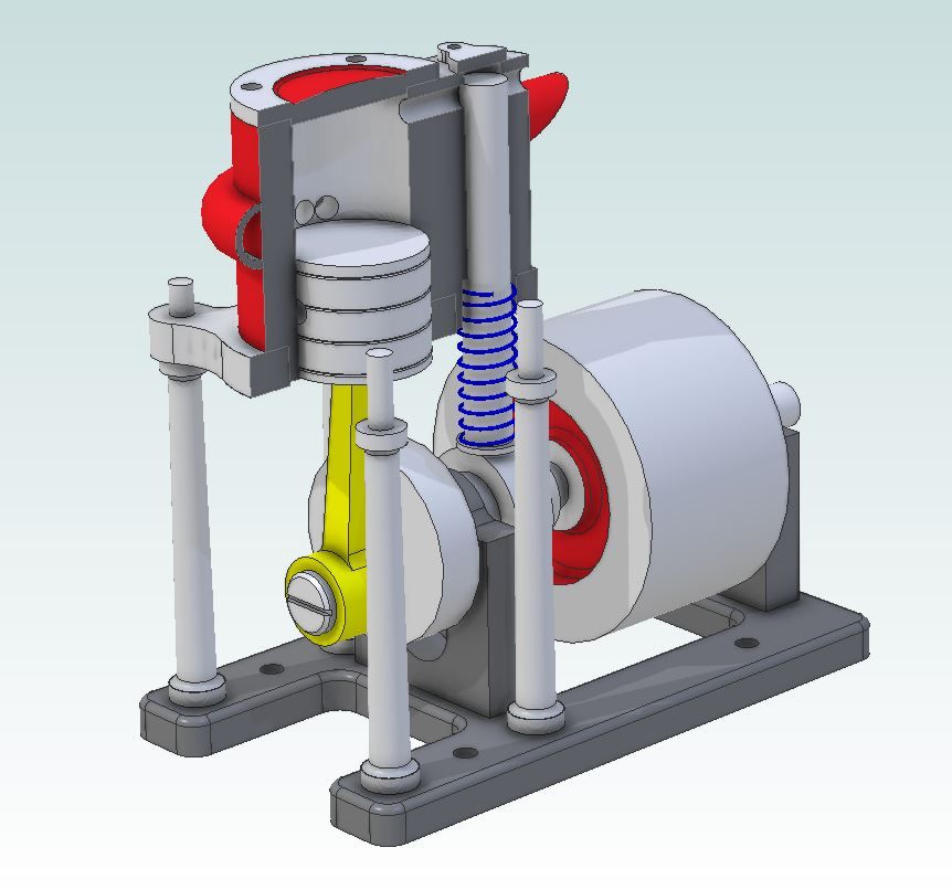
| JasonB | 03/12/2021 19:02:30 |
25215 forum posts 3105 photos 1 articles | A little more temptation, this would roughly be the poppet valve version which does not need much changing. Not shown is the cam that would need altering to work the other way as the valve now lifts to open the inlet rather than lifting to close.
|
| geoff walker 1 | 04/12/2021 09:48:57 |
| 521 forum posts 217 photos | Very nice Jason, really like your design. Will be your popular 24mm size? Can you explain to me how the exhaust works? Hope that's not a daft question. It's the dynamics that puzzle me. Is there any significance in the shape of the exhaust, twin and being wrapped around the cylinder Would it function just as well with a single exhaust pipe at the front of the cylinder. Cheers geoff |
| JasonB | 04/12/2021 10:21:37 |
25215 forum posts 3105 photos 1 articles | I've kept this one quite close to the original sizes by working with the conversion of 1/16" on the original equals 1.5mm which works out well in most cases giving whole millimetre numbers or #.5mm if a 32nd . This means that the original 3/4" bore comes out at 18mm ( 12sixteenths x 1.5mm). The Uniflow design has the inlet at the top of the cylinder and the exhaust so it is just fully uncovered when the piston reaches BDC meaning the air/steam flows in one direction. So as the valve opens around TDC the piston is pushed down, valve should close just as the exhaust ports start to get uncovered which then lets any still expanding steam out of the cylinder. On the up stroke it is only the momentum stored in the flywheel that moves the piston and that also has to compress any remaining air/steam as the exhaust and valve are closed, probably works better on steam as you will get a little condensing of what was left in the cylinder so less force needed to bring the piston back to TDC. The exhaust could just as easily be two separate stubs sticking out each side of a single at the front provided it did not reduce the area, I have seen images of it with just the bare holes. Really just comes down to how you want it to look and where you want any oily exhaust to go. This was quite likely to find it's way into a boat so out the back seems like a good idea. |
| geoff walker 1 | 04/12/2021 15:09:16 |
| 521 forum posts 217 photos | Hi Jason, Thanks for the reply, that helps a lot. I found it difficult to see how the exhaust would work efficiently with the piston leading and therefore without a stroke of the piston backing it up, so to speak. But clearly it does and seems to be in some respects a matter of having sufficient surface area to allow the expanding steam to escape. I shall follow this project with interest. I would like to make it but my big problem is I have no silver soldering facility and I assume that will be how the exhaust is attached to the cylinder. Is JBW an option? Final point. The three exhaust holes, could that be an elongated hole cut through the side with a slot drill? Cheers Geoff
|
| Niels Abildgaard | 04/12/2021 15:53:12 |
| 470 forum posts 177 photos | A little engineering can make it much sweeter running. Make piston and pin as low-mass as You dare. Put a mass on the conrod opposite piston so that piston -pin and conrod balances on the crank hole. Put countermass on crankshaft so that the hole mowing cirkus has center of mass on crank centerline. It sounds complicated but is about half an hour on a CAD system. The engine will be much,much nicer running fast. If there is interest I will make some picture. Offer me a bore (mm please) ,stroke and conrod inter hole distance and I go ballistic. |
| JasonB | 04/12/2021 16:31:25 |
25215 forum posts 3105 photos 1 articles | Posted by Niels Abildgaard on 04/12/2021 15:53:12:
If there is interest I will make some picture. Oh for a moment there I thought you were going to say you would make a better running one It was something I was going to come to in the write up, it certainly wants to jump along the workbench if not clamped down so would benifit from some shaping of the crank web, piston could be shaved a little more too, it is already made from 6082. I have done this on the previous small marine engines to help with smooth running. Bore 18mm, stroke 15mm. Conrod ctrs 39.5mm. Crank 25mm dia x 6mm thick, crank pin 6mm dia x 6.5mm long with 8mm dia x 1.5mm head
Edited By JasonB on 04/12/2021 16:38:54 |
| JasonB | 04/12/2021 16:38:20 |
25215 forum posts 3105 photos 1 articles | Geoff, yes I should think you will be OK with JBWeld and I did consider it at one time before deciding on silver solder. A slot would be fine, I expect the original was shown with drilled holes as it was the easier option for limited workshop tooling |
| JasonB | 04/12/2021 18:40:59 |
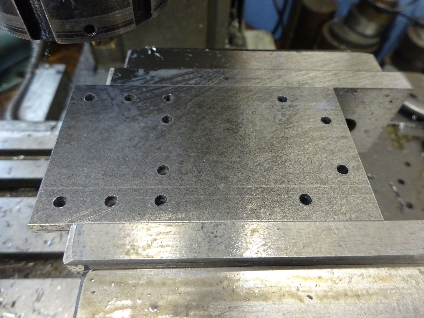
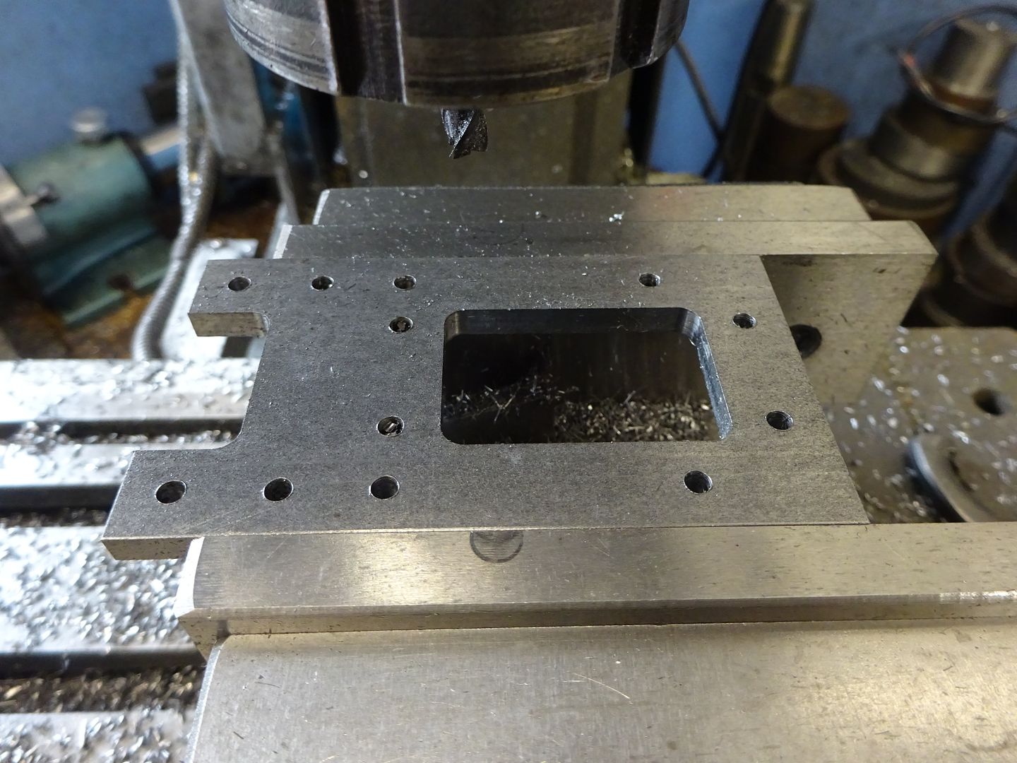
25215 forum posts 3105 photos 1 articles | I did not take many photos of this build but as there has been some interest shown by Pm and on other forums I'll add a bit of commentary to what images I do have. Starting with the base a piece of 5mm plate was milled to the overall size and then the datum located following which the various 3mm holes were drilled.
Followed by milling out some of the unwanted material firstly by doing a few passes 0.2mm inside the line and then a full depth pass to remove the last 0.2mm of material. After this the holes for the bearing blocks and columns were countersunk on the underside.
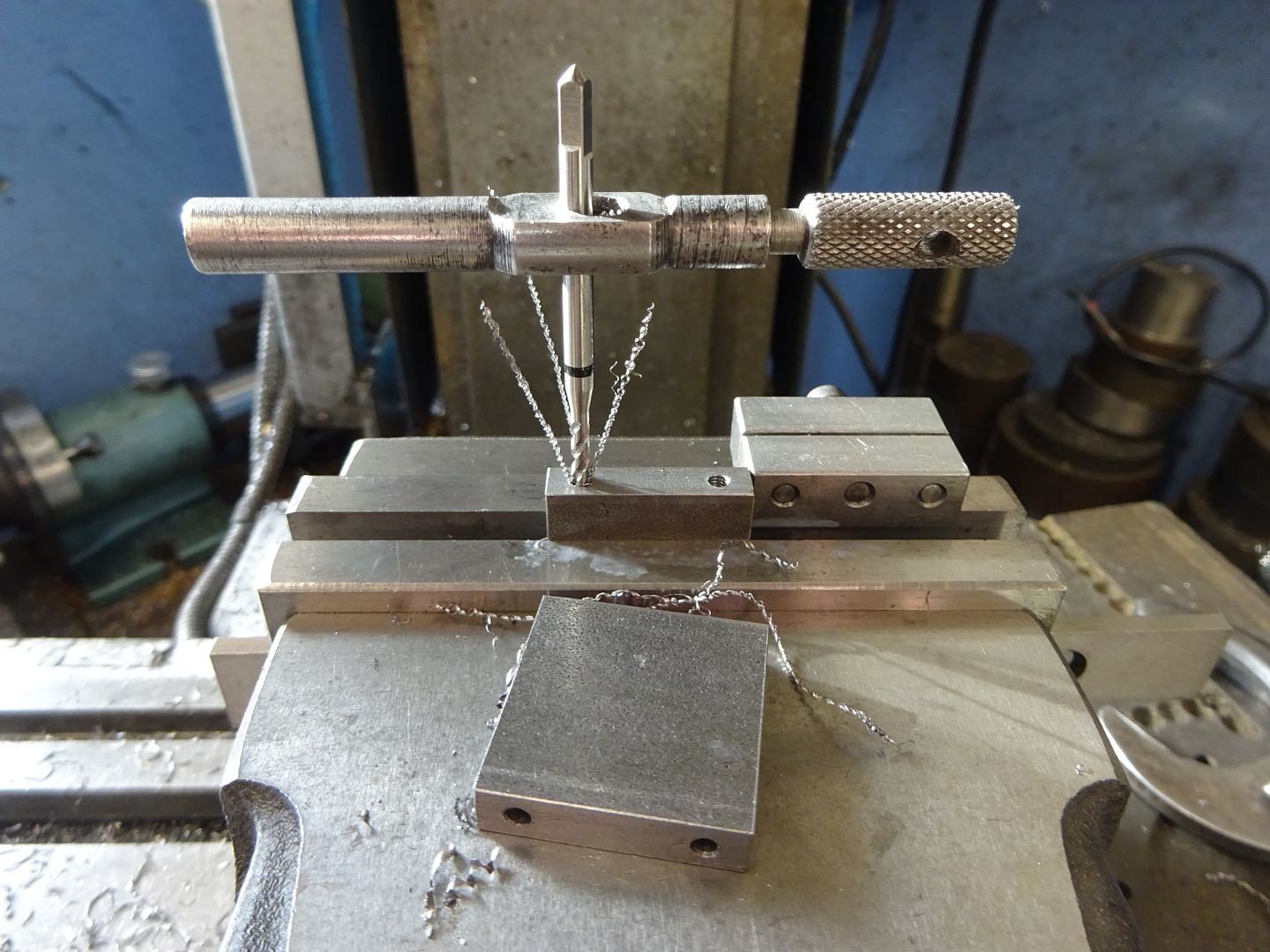
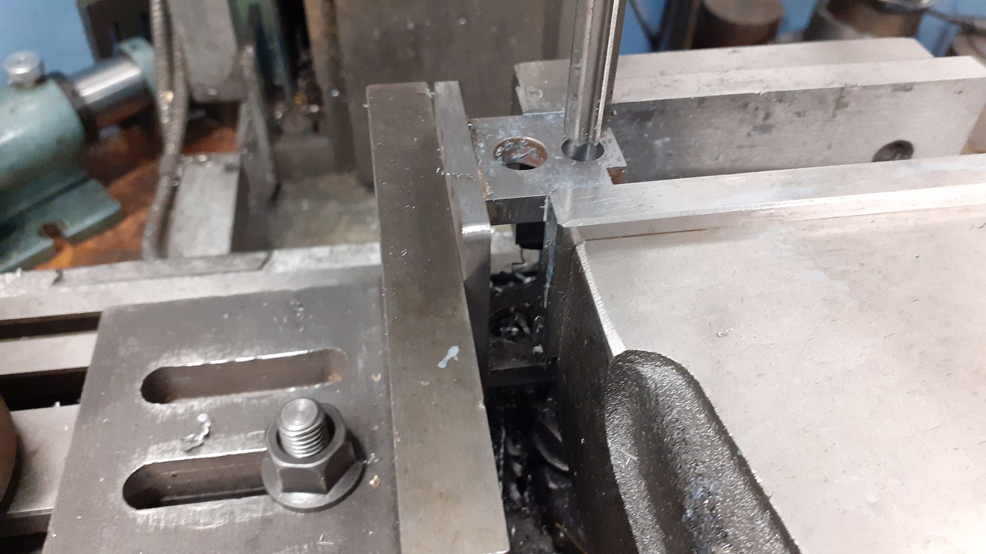
Two pieces of 6mm thick material were squared up and then drilled & tapped M3, the spiral flute tap makes tapping a quick and easy process as you don't need to keep backing the tap off to break the chips - just let them curl out the top.
It would be possible to just use a couple of CSK screws to hold the bearing blocks on or add a bit of JBWeld to get a fillet for that cast look but I opted to silver solder. Once out of the pickle the bearing holes were line bored , well actually drilled and reamed with an 8mm machine reamer.
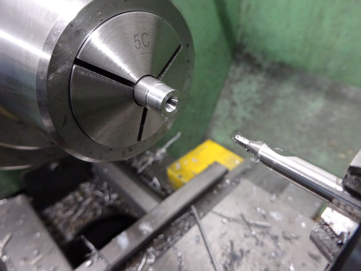
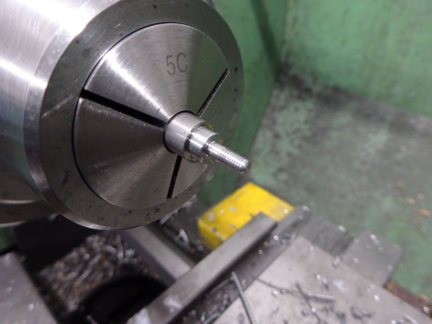
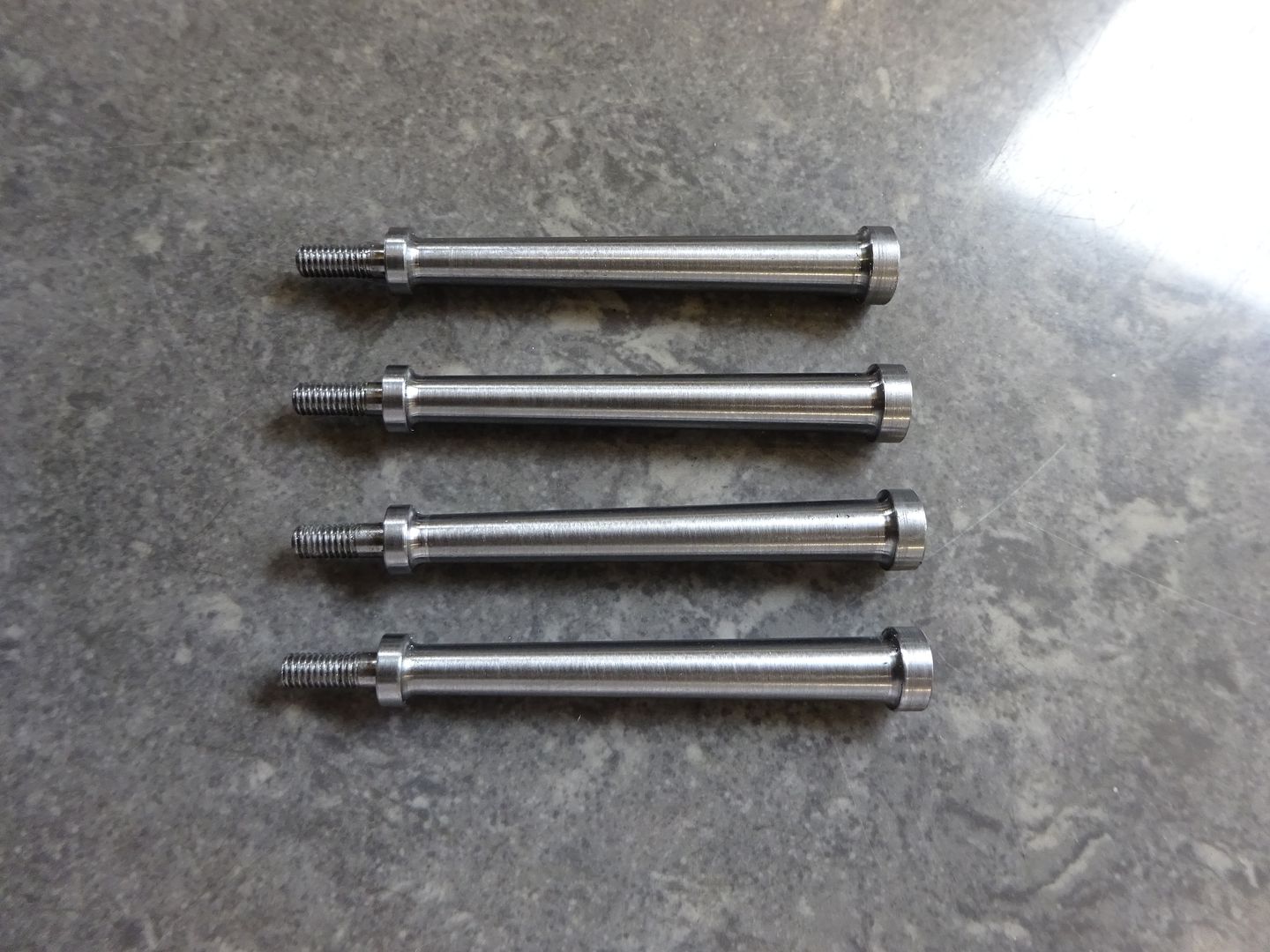
I had intended to file the curved top to the bearing caps using a couple of buttons but realised I could do it on the CNC and at just over 60seconds each quicker than I could turn up the buttons. I left the oil holes until the end once the bearings had been Loctited into place drilling both at the same time. Next up were the columns, after facing four pieces of 8mm stock to the same lengths one end of each was reduced to 7mm dia, drilled and tapped M3 and then a ctr hole drilled for later tailstock support.
The other end was reduced to 6mm and a 3mm spigot formed and threaded M3 then the end of the exposed thread rounded with a file.
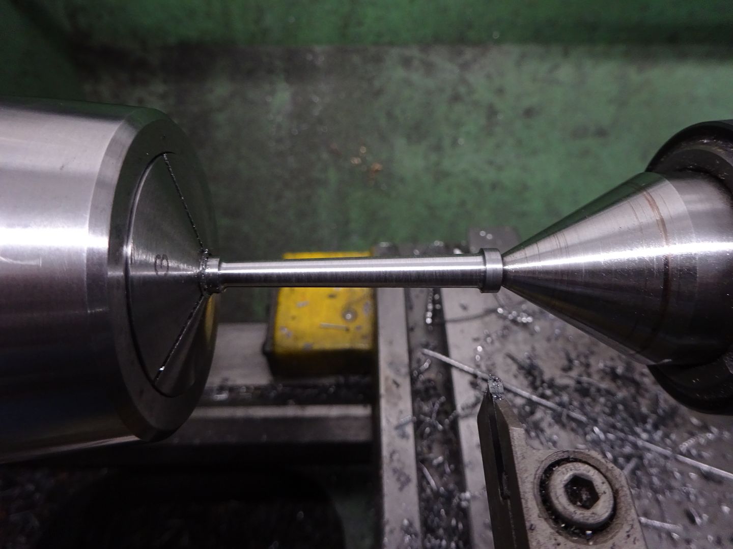
It was then just a case of holding by the 3mm section, adding tailstock support and then setting over the topslide to turn the taper. A 2mm dia grooving insert left a nice 1mm radius fillet at each end of the taper to blend into the flanges.
The crank was just a piece of 25mm bar faced off and reamed 6mm then sawn off a bit over length. This was loctited to some 6mm PGMS and once set turned down to the finished 6mm thickness before transferring to the mill for tapping the M4 hole at a throw of 7.5mm. The pin was a simple turning job followed by cutting the saw slot with a slitting saw. |
| JasonB | 04/12/2021 18:58:56 |
25215 forum posts 3105 photos 1 articles | While I was waiting that half hour I came up with this which may smooth things out. I guess this will be the Ultralite version. Counterbalanced crank web Thinned down piston with 1mm thick skirt and crown, slot rather than hole for small end Drilled out crank and wrist pins Rounded corners of conrod bosses, a change to 2014 aluminium would get the weight down a bit more
|
| Niels Abildgaard | 04/12/2021 19:38:17 |
| 470 forum posts 177 photos | First picture is the original parts as described by Jason
|
| Niels Abildgaard | 04/12/2021 19:39:40 |
| 470 forum posts 177 photos | Next picture is balance improved by Niels
|
| Niels Abildgaard | 04/12/2021 19:42:29 |
| 470 forum posts 177 photos | The conrod has got an extension so that center of mass for piston parts and conrod is at the crank hole? The crankshaft is then modified so that all moving parts are mass centered on centerline. Edited By Niels Abildgaard on 04/12/2021 19:43:13 |
| duncan webster | 05/12/2021 18:47:04 |
| 5307 forum posts 83 photos | Nice idea Nils, but what I think you've done is swapped liner vibration for rotational. The conrod/weight assembly is being accelerated/decelerated in a rotary motion, and the only force which can supply this is side force at the piston, reacted by another force at the crankshaft, so the engine assembly sees a twisting vibration. Whether this is better or worse than just balancing half the reciprocating and all the rotating mass would be an interesting experiment. The only way to fully balance a single cylinder engine is to have 2 counter-rotating weights (used in many modern motorcycles) or to have a second throw to the crank which wags a dead weight up and down (think boxer engine, but only one active cylinder). I read that Triumph (the old one, pre bankruptcy) actually drew something up on these lines |
| Niels Abildgaard | 05/12/2021 19:30:36 |
| 470 forum posts 177 photos | Posted by duncan webster on 05/12/2021 18:47:04:
Nice idea Nils, but what I think you've done is swapped liner vibration for rotational. The conrod/weight assembly is being accelerated/decelerated in a rotary motion, and the only force which can supply this is side force at the piston, reacted by another force at the crankshaft, so the engine assembly sees a twisting vibration. Whether this is better or worse than just balancing half the reciprocating and all the rotating mass would be an interesting experiment. It is my feeling that trading forces for torques is a good deal,but as you say an experiment will be nice.Then afterward everybody can join with What did I say and that is nice in this troubled times. |


Please login to post a reply.
Magazine Locator
Want the latest issue of Model Engineer or Model Engineers' Workshop? Use our magazine locator links to find your nearest stockist!
Sign up to our Newsletter
Sign up to our newsletter and get a free digital issue.
You can unsubscribe at anytime. View our privacy policy at www.mortons.co.uk/privacy
Latest Forum Posts
- *Oct 2023: FORUM MIGRATION TIMELINE*
05/10/2023 07:57:11 - Making ER11 collet chuck
05/10/2023 07:56:24 - What did you do today? 2023
05/10/2023 07:25:01 - Orrery
05/10/2023 06:00:41 - Wera hand-tools
05/10/2023 05:47:07 - New member
05/10/2023 04:40:11 - Problems with external pot on at1 vfd
05/10/2023 00:06:32 - Drain plug
04/10/2023 23:36:17 - digi phase converter for 10 machines.....
04/10/2023 23:13:48 - Winter Storage Of Locomotives
04/10/2023 21:02:11 - More Latest Posts...
- View All Topics
Support Our Partners


Shopping Partners
Subscription Offer

Latest "For Sale" Ads
- Reeves** - Rebuilt Royal Scot by Martin Evans
by John Broughton
£300.00 - BRITANNIA 5" GAUGE James Perrier
by Jon Seabright 1
£2,500.00 - Drill Grinder - for restoration
by Nigel Graham 2
£0.00 - WARCO WM18 MILLING MACHINE
by Alex Chudley
£1,200.00 - MYFORD SUPER 7 LATHE
by Alex Chudley
£2,000.00 - More "For Sale" Ads...
Latest "Wanted" Ads
- D1-3 backplate
by Michael Horley
Price Not Specified - fixed steady for a Colchester bantam mark1 800
by George Jervis
Price Not Specified - lbsc pansy
by JACK SIDEBOTHAM
Price Not Specified - Pratt Burnerd multifit chuck key.
by Tim Riome
Price Not Specified - BANDSAW BLADE WELDER
by HUGH
Price Not Specified - More "Wanted" Ads...
Get In Touch!
Do you want to contact the Model Engineer and Model Engineers' Workshop team?
You can contact us by phone, mail or email about the magazines including becoming a contributor, submitting reader's letters or making queries about articles. You can also get in touch about this website, advertising or other general issues.
Click THIS LINK for full contact details.
For subscription issues please see THIS LINK.
Digital Back Issues


Donate

 Register
 Log-in
Model Engineer Magazine
- Percival Marshall
- M.E. History
- LittleLEC
- M.E. Clock

ME Workshop
- An Adcock
- & Shipley
- Horizontal
- Mill

Subscribe Now
- Great savings
- Delivered to your door

Pre-order your copy!
- Delivered to your doorstep!
- Free UK delivery!
All Forum Topics > Stationary engines > A Lightweight Husky