Forum sponsored by:

Grinding Tool Bits from Cylindrical HSS Blanks
| William Harvey 1 | 02/10/2021 13:51:13 |
| 176 forum posts | Hi, I was about to posts this and saw the thread on Grinding Tool Bits. The thread seems to cover standard square HSS tool bits, but I need to cut a tool bit from a piece of cylindrical HSS blank. I have a thread showing a custom fly cutter / single point end cutter that I am trying to make. It is basically a fly cutter with a pilot guide in the base. To keep things simple I was advise to use cylindrical HSS so that I only need to drill a hole for the tool bit to fit in and secure it with a grub screw at 90 degrees. For ease here I have extracted the info from the other thread ref the tool bit here. Posted by William Harvey 1 on 02/07/2021 10:27:05:Posted by Stueeee on 01/07/2021 21:35:14: Machine the cutter from a single piece of mild steel. Doesn't need to be anything fancy; I usually use EN3B, EN1A should be OK too. 'A' series valves are 9/32 diameter, so that's going to be the size you're going to machine your pilot to. Once you've machined the pilot, put the job in a pair of vee blocks and drill across the piece immediately above the 9/32" section to the same size as whatever piece of round HSS you're going to use. Once that's done, turn the piece 90 degrees and drill the hole for the grubscrew. The drilled hole needs to be the tapping size for whatever size grubscrew you choose. It needs to be smaller than the toolbit diameter; e.g. if you are using a 5/16" diameter toolbit, then aim for a 1/4" or 6mm grubscrew. At the top of the piece crossdrill again for the tommy bar. Re. grinding the toolbit, to produce a flat cut, the cutting edge needs to be at 90 degrees to the pilot. Orientate the tool bit in the hole so that it has zero or negative rake, otherwise the toolbit will 'dig in' while you're cutting. Extracted Thread Stops here. So, following that advice I bought the 5/16 HSS and some 6mm Grub Screws The tool is based on this image, however the tool in the image is for cutting an angled valve seat. The tool I am making is for cutting a reference cut in the valve seat area for lowering the chamber floor (or more accurately, raising the chamber roof). So instead of a radiused cutting tip the cutting tip will be flat.
In the image below, this is what I believe the tool tip will need to look like, to achieve the recessed cut around the valve seat area. The image below shows a clearance of 5 - 8 degrees, however instead of positive rake (as in the image below) my tool bit will need a negative rake.
In the image above I assume we are looking directly at the end of the tool bit. I see from the Grinding Tool Bit thread, cutting HSS is hard. The piece I have is 100mm and I need to cut it in half - what's the best way to do this? I bought a White Grinding Wheel to grind the bit, but don't have a tool bit grinding rest? Can anyone point me to any guides or videos on making and sharpening a square ended round cutting tool from a round piece of HSS? Many thanks
|
| JasonB | 02/10/2021 14:06:37 |
 25215 forum posts 3105 photos 1 articles | As your blank is cylindrical you only need to grind it to the half way point and you will then get all the side clearance needed, then grind the end to give 5 to 10 degrees of clearance. Does not have to be too accurate an angle, I don't have anything special on my grinder just eyeball it. To cut the HSS into smaller pieces use a thin parting disk or the corner of your grinding wheel to just cut a notch approx 1mm deep. hold in a vice with notch just above the jaws and hit with a hammer. Advisable to put a rag over the end so it does not fly off.
Edited By JasonB on 02/10/2021 14:35:39 |
| DiogenesII | 02/10/2021 16:30:24 |
| 859 forum posts 268 photos | Posted by William Harvey 1 on 02/10/2021 13:51:13:
...the image below... ...however instead of positive rake (as in the image below) my tool bit will need a negative rake...
In the image above I assume we are looking directly at the end of the tool bit. Many thanks Not sure that I understand the need for negative rake - it is an 'aluminium' head? ..surely cutting this will need similar (if not even a little more) positive rake as shown..? |
| William Harvey 1 | 02/10/2021 16:55:13 |
| 176 forum posts | Posted by DiogenesII on 02/10/2021 16:30:24:
Posted by William Harvey 1 on 02/10/2021 13:51:13:
...the image below... ...however instead of positive rake (as in the image below) my tool bit will need a negative rake...
In the image above I assume we are looking directly at the end of the tool bit. Many thanks Not sure that I understand the need for negative rake - it is an 'aluminium' head? ..surely cutting this will need similar (if not even a little more) positive rake as shown..? Old A Series Mini / Mini Metro Engine, Cast Iron, not Aluminium |
| JasonB | 02/10/2021 17:03:24 |
25215 forum posts 3105 photos 1 articles | How much are you intending to cut as I would think Chatter will be an issue once the cutter engagement gets to 3mm or so. Is this the sort of thing you are trying to do?
|
| William Harvey 1 | 02/10/2021 17:58:37 |
| 176 forum posts | Posted by JasonB on 02/10/2021 17:03:24:
How much are you intending to cut as I would think Chatter will be an issue once the cutter engagement gets to 3mm or so. Is this the sort of thing you are trying to do?
Very similar tool. Only looking at remove around 0.025" from the existing level. |
| JasonB | 02/10/2021 18:31:36 |
25215 forum posts 3105 photos 1 articles | So as I said a simple way would be to grind to half diameter
Then grind the end to 5-10 degrees
That 5-10 degrees will need to be enough so that there is clearance behind the tool as it swings in a circle as arrowed
Slight rotation of the tool in the holder will take you from zero rake to negative but I don't think that will be needed
If you wanted to run with positive rake then you would need to add a third ground surface meeting the first at say 80degrees which would allow about 5deg positive rake to the front of the tool a sit is rotated in the holder
Edited By JasonB on 02/10/2021 18:43:11 |
| William Harvey 1 | 02/10/2021 20:53:31 |
| 176 forum posts | Posted by JasonB on 02/10/2021 18:31:36:
So as I said a simple way would be to grind to half diameter Slight rotation of the tool in the holder will take you from zero rake to negative but I don't think that will be needed Edited By JasonB on 02/10/2021 18:43:11 That absolutely brilliant, thank you so much. With regards to holding the tool bit in place with the 6mm grub screw, will this on its own be sufficient to hold the in position. I was thinking of grinding a flat run but it would have to be correctly positioned to ensure correct positioning to ensure the correct rake of the tool bit? |
| JasonB | 03/10/2021 06:49:29 |
25215 forum posts 3105 photos 1 articles | A single grub screw should do the job OK |
| William Harvey 1 | 03/10/2021 10:21:53 |
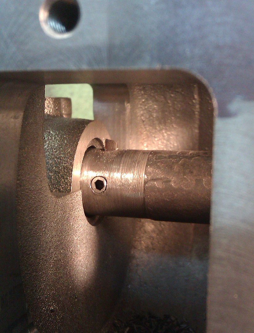
| 176 forum posts | Quick question. How much material can I safely leave in the tool head below the tool bit, without it fracturing? Here is a pic showing the centre of the 5/16" bit being positions 14mm from the base - this leaves 10mm below the base of the tool bit:
And another showing the central hole being at 9mm which leaves 5mm below the tool bit?
As mentioned tool is being designed to cut very shallow depths, but what if I wanted to say use it to enlarge the valve throat. Obviously I would be restricted to bottoming out on the base of the throat. |
| JasonB | 03/10/2021 13:02:46 |
25215 forum posts 3105 photos 1 articles | the 9mm should be fine |
| William Harvey 1 | 11/10/2021 09:07:10 |
| 176 forum posts | Posted by JasonB on 03/10/2021 13:02:46:
the 9mm should be fine Done - well the tool holder at least
According to one of the cylinder head modification guides I am using, I need to put a radius on the bottom outer edge of the cutting tool of 0.040". This will ensure that the corner of the chamber will not be has a sharp edge. I guess I just touch the corner of the tool with grinding wheel to achieve this?
|
| Grindstone Cowboy | 11/10/2021 11:17:43 |
| 1160 forum posts 73 photos | I'd give it a rub on an oilstone, you don't want to take too much off and have to start again. Rob |
| Nigel Graham 2 | 11/10/2021 19:06:53 |
| 3293 forum posts 112 photos | A simple grinding-holder made by appropriately drilling and tapping a short length of square-section bar to hold the tool-bit protruding from its end, will help make the process easier, safer and more accurate. It helps too if the grinder's tool-rest is a larger plate than the usual bit of strip-steel, if yours is a basic bench-grinder (as mine is). |


Please login to post a reply.
Magazine Locator
Want the latest issue of Model Engineer or Model Engineers' Workshop? Use our magazine locator links to find your nearest stockist!
Sign up to our Newsletter
Sign up to our newsletter and get a free digital issue.
You can unsubscribe at anytime. View our privacy policy at www.mortons.co.uk/privacy
Latest Forum Posts
- hemingway ball turner
04/07/2025 14:40:26 - *Oct 2023: FORUM MIGRATION TIMELINE*
05/10/2023 07:57:11 - Making ER11 collet chuck
05/10/2023 07:56:24 - What did you do today? 2023
05/10/2023 07:25:01 - Orrery
05/10/2023 06:00:41 - Wera hand-tools
05/10/2023 05:47:07 - New member
05/10/2023 04:40:11 - Problems with external pot on at1 vfd
05/10/2023 00:06:32 - Drain plug
04/10/2023 23:36:17 - digi phase converter for 10 machines.....
04/10/2023 23:13:48 - More Latest Posts...
- View All Topics
Support Our Partners


Shopping Partners
Subscription Offer

Latest "For Sale" Ads
- Reeves** - Rebuilt Royal Scot by Martin Evans
by John Broughton
£300.00 - BRITANNIA 5" GAUGE James Perrier
by Jon Seabright 1
£2,500.00 - Drill Grinder - for restoration
by Nigel Graham 2
£0.00 - WARCO WM18 MILLING MACHINE
by Alex Chudley
£1,200.00 - MYFORD SUPER 7 LATHE
by Alex Chudley
£2,000.00 - More "For Sale" Ads...
Latest "Wanted" Ads
- D1-3 backplate
by Michael Horley
Price Not Specified - fixed steady for a Colchester bantam mark1 800
by George Jervis
Price Not Specified - lbsc pansy
by JACK SIDEBOTHAM
Price Not Specified - Pratt Burnerd multifit chuck key.
by Tim Riome
Price Not Specified - BANDSAW BLADE WELDER
by HUGH
Price Not Specified - More "Wanted" Ads...
Get In Touch!
Do you want to contact the Model Engineer and Model Engineers' Workshop team?
You can contact us by phone, mail or email about the magazines including becoming a contributor, submitting reader's letters or making queries about articles. You can also get in touch about this website, advertising or other general issues.
Click THIS LINK for full contact details.
For subscription issues please see THIS LINK.
Digital Back Issues


Donate

 Register
 Log-in
Model Engineer Magazine
- Percival Marshall
- M.E. History
- LittleLEC
- M.E. Clock

ME Workshop
- An Adcock
- & Shipley
- Horizontal
- Mill

Subscribe Now
- Great savings
- Delivered to your door

Pre-order your copy!
- Delivered to your doorstep!
- Free UK delivery!
All Forum Topics > Beginners questions > Grinding Tool Bits from Cylindrical HSS Blanks