Forum sponsored by:

General mill engine design
| AStroud | 14/07/2021 16:41:41 |
| 44 forum posts 12 photos | Hi All Having built a Potty mill engine, a Monitor and an MEM Corliss for my next build I am planning an own design mill engine. I want it to be slow running and silent. I seem to remember a bore to stroke of 1:2 is good and a connecting rod length of c. 5 x the stroke gives a pleasant motion, is that about right ? Am I also right in saying as long as the steam ports 'match' the eccentric throw then the steam chest size and dimensions do not really matter as long as the ports are large enough for the estimated air flow ? I want to eliminate any possible sources of knock, I know that means tight bearing tolerances but any recommendations out there to minimize mechanical noise ? thanks for any advice Andrew |
| Jon Lawes | 14/07/2021 16:48:34 |
 1078 forum posts | Do you plan to run on air or steam? Your valve timing will be dictated by your choice. I'm currently doing a similar project. As with yours, I want it to run very smoothly at low pressure and speed so as to be a nice display engine. |
| JasonB | 14/07/2021 17:23:33 |
 25215 forum posts 3105 photos 1 articles | Those proportions sound about right for a slow running engine. Similar to the Stuart Victoria and the Thompston that I have just had covered in ME mag. Steam chest size does not really affect much so can be made to suit what looks pleasing to the eye. As Jon says timing usually needs less lead with air than it does with steam but that's just down to the position of the eccentric. As for avoiding knocks then you want good close fits on all the bearings, cross head and various pivot pins as any excess will show up as a knock at either end of the stroke. I like to bore as many of these as possible you I can get the feel right but do have to resort to reamers for things like cross head pins and smaller ones in the valve linkages. Also keep friction from gland packing a slow as possible and if just ticking over for display then you can leave any piston ring out provided you have a good bore/piston fit. That way you should be able to run on a couple of psi of air and get a nice slow tick over. |
| AStroud | 14/07/2021 21:27:10 |
| 44 forum posts 12 photos | Thanks. Yes I am planning to run on air. Another objective was to build from my existing material stock, so preliminary design is 1" bore x 2 1/4" stroke, a tubular crosshead guide from material left over from the Corliss build and a 7" dia flywheel. I do not have material to fabricate a base frame so it will sit on a 6mm plate, probably on a plinth made from wood. Minimising the gland and piston seals sounds like a good tip but I don't like the sound of constant hissing indicating leaks either so a trade off is needed. |
| Andrew Johnston | 14/07/2021 22:13:29 |
 7061 forum posts 719 photos | Posted by AStroud on 14/07/2021 16:41:41: Am I also right in saying as long as the steam ports 'match' the eccentric throw then the steam chest size and dimensions do not really matter as long as the ports are large enough for the estimated air flow ? If you do the maths you'll find that the size of the steam chest does matter. It acts as reservoir to minimise pressure drop when the inlet ports are open. Of course if the supply pipe from the source to the valve has a much larger area than the inlet port then the size of chest is less important as the supply pipe takes over the reservoir function. But the pipe might look a bit non-scale. Andrew |
| Ramon Wilson | 14/07/2021 23:14:46 |
 1655 forum posts 617 photos | Hello Andrew (Stroud), I much prefer to see an engine running slow and throughout a build pay close attention to running fits as the build progresses rather than at the end. Friction and tight spots is the bug bear of slow running. I have long been a keen advocate of using PTFE impregnated yarn as a piston seal on engines to be run on air. Piston/liner tolerances can be relaxed considerably to give a virtually frictionless fit whilst giving a superb compressive seal. I prefer using graphite yarn - unravelled to provide a single strand - for the glands. I have made my slide valves with no lap. If your design is to feature an outrigger bearing pedestal then the crank shaft needs to be exactly parrallel to the cross head pin and con rod bearings. If not even the slightest angle means the crankpin plane is out of square and this will induce a knock - however slight the error. Good luck with your project Tug
|
| JasonB | 15/07/2021 07:38:33 |
25215 forum posts 3105 photos 1 articles | Posted by Andrew Johnston on 14/07/2021 22:13:29:
Posted by AStroud on 14/07/2021 16:41:41: Am I also right in saying as long as the steam ports 'match' the eccentric throw then the steam chest size and dimensions do not really matter as long as the ports are large enough for the estimated air flow ? If you do the maths you'll find that the size of the steam chest does matter. It acts as reservoir to minimise pressure drop when the inlet ports are open. Of course if the supply pipe from the source to the valve has a much larger area than the inlet port then the size of chest is less important as the supply pipe takes over the reservoir function. But the pipe might look a bit non-scale. Andrew I have not done the maths but instinct tells me that this will become more of a factor as running pressure goes up, if we are talking of running an a couple of psi then the chest will not be storing as much as it would if running at 100psi. There is also the lack of expansion with air running compared to steam which may also make chest size less critical. The Stuarts have a fair volume in the chests but some of Anthony Mount's designs like the Benson ( my Muncaster uses same design) are very tight but I've been able to get then both ticking over slowly. On home build engines or those with small cast cylinders where the passages are mostly drilled rather than cast in the area of the passage is usually less than that of the (exposed) port area which is where the restriction may be so keeping the supply equal to or above that will also help with air flow. My Filer & Stow with it's rocking valve has zero space around the valve and will run fast or slow, Corliss engines don't really have a chest but going by Ramon's run quite slow and smooth Andrew(S) you should not get hissing from leaking air, it's just a case of not winding in the gland nuts and over compressing the yarn packing. Think about putting your finger on the end of the air hose, at 5psi you won't need to apply much force to stop air escaping, at 100psi you will need a lot more force, the packing is your finger. If the cylinder did let by a little you won't hear that as there is almost always air being exhausted from one side of the piston anyway, though the fit I go for is quite close. Edited By JasonB on 15/07/2021 07:57:43 |
| AStroud | 15/07/2021 09:09:22 |
| 44 forum posts 12 photos | Some interesting points made, thanks. I think Ramon's advice about ensuring parallelism between the crankshaft pin and cross head pin is spot on and is probably the cause of a small knock I have on my Corliss which instinctively makes you think is bearing clearances somewhere but I cannot find any. I need to think of a way to check the alignment with my limited equipment. Andrew |
| JasonB | 15/07/2021 09:26:46 |
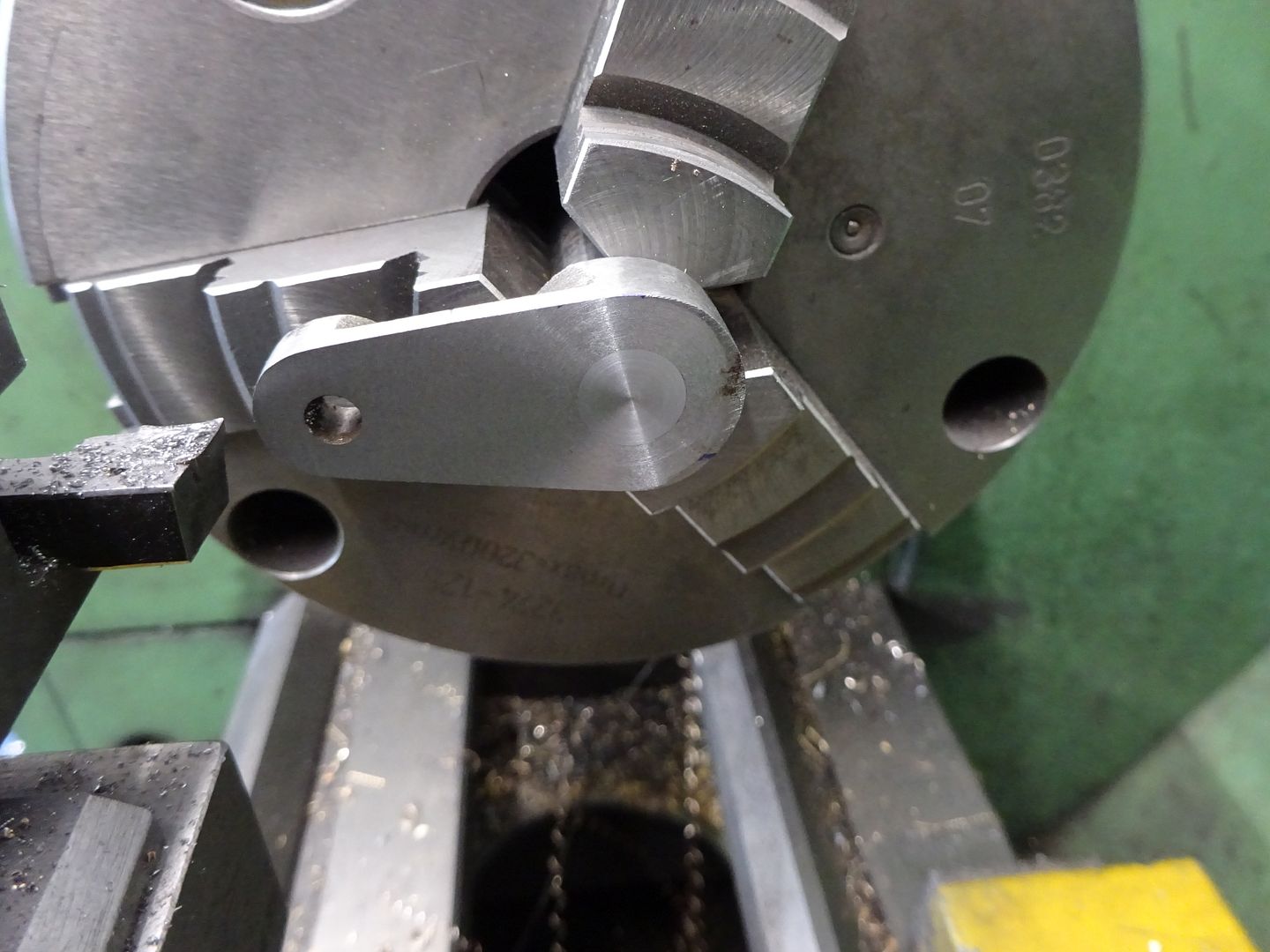
25215 forum posts 3105 photos 1 articles | Without pulling the engine apart too much you could slip the cross head pin out and move the cross head by hand so the small end is not in the slot. compare where the little end is at TDC and BDC to see if there is any sideways difference. With that type of crankshaft the fit of the crank onto the shaft can make a lot of difference as if the flat face of the crank is off then the pin's axis will be too so I always like to make the crank a bit thicker and then assemble onto the shaft before taking a final skim to get the face true to the shaft's axis. The MEM plans just call for a 3/8" hole and 3/8" MS shaft. any slop in this will affect how true the web is to the shaft, really needs the hole boring to fit the actual not nominal size of the shaft. Also relieve the base of the thread or hole so the pin screws right in and sits flat, true thread goes without saying. The Victoria that I made recently was a good example, it was part made when I got it with crank fitted and pinned to shaft but the crank was at an angle, this picture shows it with 12thou already taken off and you can just see there is still a little more to go so that is something like 15thou over 1.5". As the pin is screwed down to that surface the rod will therefor also be running at a similar angle so that's more like 0.060" over the rods 6" length which equates to a lot of sideways movement at the little end. If your chuck is not good use a collet or split bush so shaft is as true as possible.
Edited By JasonB on 15/07/2021 09:48:53 Edited By JasonB on 15/07/2021 10:00:14 |
| Andrew Johnston | 15/07/2021 09:51:27 |
7061 forum posts 719 photos | Oooops, looks like I was getting confused between engineering and modelling regarding the steam chest. Andrew |
| JasonB | 15/07/2021 10:21:34 |
25215 forum posts 3105 photos 1 articles | Though still raises the point that a working engine driven by steam that has rocking, corliss or piston valves would generally have a lot less "chest volume" than a spacious slide valve design, even the closeness of the regulator would have an effect At the other end of the scale the requirements for a compound engine running on steam mean that it needs the chest and pipework from HP exhaust to act as a receiver, could be why triple expansion engines don't run well if at all on air unless you start fiddling about with them. Thinking about it the lack of chest volume may be a good thing for slow air running as any build up may push the piston harder than you really want. Ramon also mentioned lap, with no lap there is not going to really be any time for pressure to build up in the chest as neither port is closed for any length of time. It's all engineering, just different requirements as a model that is to do work needs to be treated differently to a model that is just for display and I expect indicator diagrams would be quite different for the two. |
| AStroud | 15/07/2021 11:17:57 |
| 44 forum posts 12 photos | Thank you Jason, good advice about machining the crank and pin, I will follow your sequence for my new build and I will take a lot more care with the alignments. Andrew |
Please login to post a reply.
Magazine Locator
Want the latest issue of Model Engineer or Model Engineers' Workshop? Use our magazine locator links to find your nearest stockist!
Sign up to our Newsletter
Sign up to our newsletter and get a free digital issue.
You can unsubscribe at anytime. View our privacy policy at www.mortons.co.uk/privacy
Latest Forum Posts
- *Oct 2023: FORUM MIGRATION TIMELINE*
05/10/2023 07:57:11 - Making ER11 collet chuck
05/10/2023 07:56:24 - What did you do today? 2023
05/10/2023 07:25:01 - Orrery
05/10/2023 06:00:41 - Wera hand-tools
05/10/2023 05:47:07 - New member
05/10/2023 04:40:11 - Problems with external pot on at1 vfd
05/10/2023 00:06:32 - Drain plug
04/10/2023 23:36:17 - digi phase converter for 10 machines.....
04/10/2023 23:13:48 - Winter Storage Of Locomotives
04/10/2023 21:02:11 - More Latest Posts...
- View All Topics
Support Our Partners


Shopping Partners
Subscription Offer

Latest "For Sale" Ads
- Reeves** - Rebuilt Royal Scot by Martin Evans
by John Broughton
£300.00 - BRITANNIA 5" GAUGE James Perrier
by Jon Seabright 1
£2,500.00 - Drill Grinder - for restoration
by Nigel Graham 2
£0.00 - WARCO WM18 MILLING MACHINE
by Alex Chudley
£1,200.00 - MYFORD SUPER 7 LATHE
by Alex Chudley
£2,000.00 - More "For Sale" Ads...
Latest "Wanted" Ads
- D1-3 backplate
by Michael Horley
Price Not Specified - fixed steady for a Colchester bantam mark1 800
by George Jervis
Price Not Specified - lbsc pansy
by JACK SIDEBOTHAM
Price Not Specified - Pratt Burnerd multifit chuck key.
by Tim Riome
Price Not Specified - BANDSAW BLADE WELDER
by HUGH
Price Not Specified - More "Wanted" Ads...
Get In Touch!
Do you want to contact the Model Engineer and Model Engineers' Workshop team?
You can contact us by phone, mail or email about the magazines including becoming a contributor, submitting reader's letters or making queries about articles. You can also get in touch about this website, advertising or other general issues.
Click THIS LINK for full contact details.
For subscription issues please see THIS LINK.
Digital Back Issues


Donate

 Register
 Log-in
Model Engineer Magazine
- Percival Marshall
- M.E. History
- LittleLEC
- M.E. Clock

ME Workshop
- An Adcock
- & Shipley
- Horizontal
- Mill

Subscribe Now
- Great savings
- Delivered to your door

Pre-order your copy!
- Delivered to your doorstep!
- Free UK delivery!
All Forum Topics > General Questions > General mill engine design