Forum sponsored by:

The Senior - The Engineers’ Emporium
| Bert Francis | 19/05/2021 21:14:36 |
| 1 forum posts | Hello all,
I’m considering the viability of building The Senior (internal combustion) engine, sold as castings by The Engineers’ Emporium. It’s advertised as being possible to build on a “Myford or similar capacity lathe”, with references to a 3.5” lathe being acceptable. I have a Myford Super 7 (no milling machine, but a vertical slide) - how realistic is this likely to be? I think my primary concern would be the main bed casting: the face which mounts to the cylinder, and the main bearing cap ‘flats’. Can these be achieved on a Myford 7? I’d very much welcome the thoughts of those with experience! Creative set-ups aren’t my forte, but I’m eager to learn Many thanks, Bert |
| Hopper | 21/05/2021 06:58:25 |
 7881 forum posts 397 photos | No experience. But the spec says 7" flywheels and 8" overall length so should be doable in a Myford with the faceplate. In a pinch you could bolt the bed to the cross slide and machine it with a flycutter. |
| JasonB | 21/05/2021 07:13:34 |
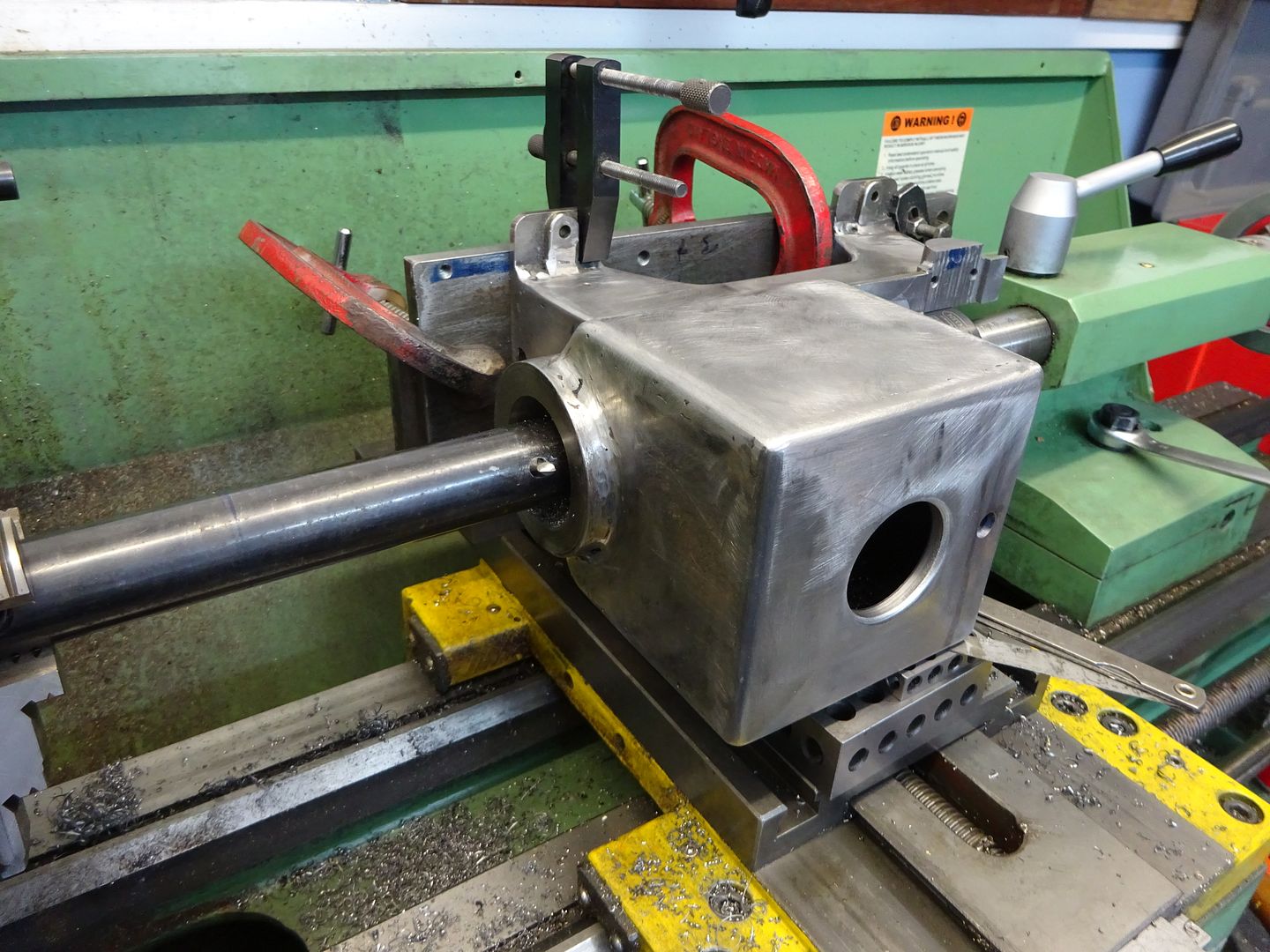
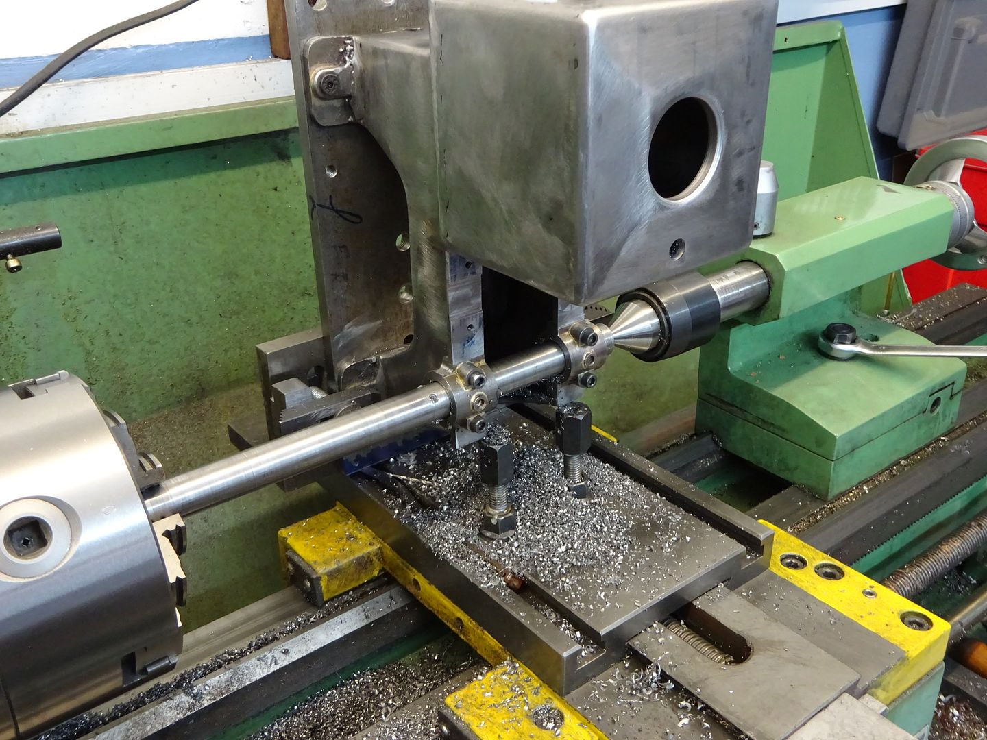
 25215 forum posts 3105 photos 1 articles | You will likely have to mount the bed casting on it's side and end to machine it on a Myford as you are unlikely to have the height above the cross slide to do it sitting the right way up Once the bottom of the bed is flat which may well have to be done by hand drill the mounting holes and then screw it to a rectangular plate as that will make it easier to clamp and you can run a dti along the plate to check for square. You then need to get inventive with angle plates etc to bore the hole for the end of the cylinder liner and flycut at the same setting, then reposition to bore the main bearings which are likely to be the hardest to set up as the front mounting lug looks like it is at least 3.5" beyond the vertical ctr line of the crank. Something like these setups
Edited By JasonB on 21/05/2021 07:15:02 Edited By JasonB on 21/05/2021 07:31:33 |
| DMB | 21/05/2021 08:34:23 |
| 1585 forum posts 1 photos | Streuth! Looks like you dont have a mill, JasonB. John |
| JasonB | 21/05/2021 09:11:03 |
25215 forum posts 3105 photos 1 articles | Just felt it was the better setup for the job, having 5-6" of cutter sticking out of a boring head can start to flex a bit so the between ctrs bar keeps things parallel and you get a nice steady cut with carriage feed. Also add to that the length of a boring head and the part which is 11" long and you can run out of head room on all 3 of my mills |
Please login to post a reply.
Magazine Locator
Want the latest issue of Model Engineer or Model Engineers' Workshop? Use our magazine locator links to find your nearest stockist!
Sign up to our Newsletter
Sign up to our newsletter and get a free digital issue.
You can unsubscribe at anytime. View our privacy policy at www.mortons.co.uk/privacy
Latest Forum Posts
- hemingway ball turner
04/07/2025 14:40:26 - *Oct 2023: FORUM MIGRATION TIMELINE*
05/10/2023 07:57:11 - Making ER11 collet chuck
05/10/2023 07:56:24 - What did you do today? 2023
05/10/2023 07:25:01 - Orrery
05/10/2023 06:00:41 - Wera hand-tools
05/10/2023 05:47:07 - New member
05/10/2023 04:40:11 - Problems with external pot on at1 vfd
05/10/2023 00:06:32 - Drain plug
04/10/2023 23:36:17 - digi phase converter for 10 machines.....
04/10/2023 23:13:48 - More Latest Posts...
- View All Topics
Support Our Partners


Shopping Partners
Subscription Offer

Latest "For Sale" Ads
- Reeves** - Rebuilt Royal Scot by Martin Evans
by John Broughton
£300.00 - BRITANNIA 5" GAUGE James Perrier
by Jon Seabright 1
£2,500.00 - Drill Grinder - for restoration
by Nigel Graham 2
£0.00 - WARCO WM18 MILLING MACHINE
by Alex Chudley
£1,200.00 - MYFORD SUPER 7 LATHE
by Alex Chudley
£2,000.00 - More "For Sale" Ads...
Latest "Wanted" Ads
- D1-3 backplate
by Michael Horley
Price Not Specified - fixed steady for a Colchester bantam mark1 800
by George Jervis
Price Not Specified - lbsc pansy
by JACK SIDEBOTHAM
Price Not Specified - Pratt Burnerd multifit chuck key.
by Tim Riome
Price Not Specified - BANDSAW BLADE WELDER
by HUGH
Price Not Specified - More "Wanted" Ads...
Get In Touch!
Do you want to contact the Model Engineer and Model Engineers' Workshop team?
You can contact us by phone, mail or email about the magazines including becoming a contributor, submitting reader's letters or making queries about articles. You can also get in touch about this website, advertising or other general issues.
Click THIS LINK for full contact details.
For subscription issues please see THIS LINK.
Digital Back Issues


Donate

 Register
 Log-in
Model Engineer Magazine
- Percival Marshall
- M.E. History
- LittleLEC
- M.E. Clock

ME Workshop
- An Adcock
- & Shipley
- Horizontal
- Mill

Subscribe Now
- Great savings
- Delivered to your door

Pre-order your copy!
- Delivered to your doorstep!
- Free UK delivery!
All Forum Topics > Beginners questions > The Senior - The Engineers’ Emporium