Forum sponsored by:

A monoblock twin study
Started years ago, lost interest, now I try to finish it
| Gerhard Novak | 22/02/2021 14:08:26 |
 109 forum posts 114 photos | Years ago (and I mean many years) I started work on a twin engine, where the cylinders are made from one block of brass stock. The machine is rather small, bore 12mm, stroke 13mm. Unfortunately I lost my drawings (probably threw them away during some miserable phase). The cylinderblock was moved from Austria to Italy, and from Italy to the UK. It has probably survived 8 house-moves. Now, just finishing my late fathers Stuart 10v which I found in a rather rusty condition, I decided to do something with this old cylinder block.
There were no pistons in the machine - so I made some, just to see how bad it has been machined. And - I am surprised - after some playing around I could make them to move quite free inside their block. So this brought me to the decision not to throw the thing into the scrap metal box at the New Bradwell dump - sorry - MK waste disposal and recycling centre - but to start re-doing the drawing. Well, I am an engineer, I have some past (25 years ago...) experience with autocad - so on we go. Autocad is too expensive for an almost retired part time worker so I use QCAD, where I have a little bit of experience in. Pretty time consuming, and I am far away from where I want to be, but I can say it should be possible, if I can machine a crankshaft which is neat enough for this machine. I had my doubts if there is enough space for the valve excenter between bearing block and crank. Just measured 10.9mm on my drawing, so it should be doable. If you want to see if it ends up in the dump finally - watch this space....
|
| Michael Gilligan | 22/02/2021 14:38:25 |
 23121 forum posts 1360 photos | Should be an interesting ‘design & build’ to follow ... Good luck with it. MichaelG. |
| Gerhard Novak | 02/03/2021 19:53:40 |
109 forum posts 114 photos | A little bit of work in QCAD - and putting the parts together it looks like this. There are still a few bits missing, but it can be seen how it will look. Back into the workshop to transfer some of my ideas from paper to metal...
|
| Gerhard Novak | 13/04/2021 18:31:42 |
109 forum posts 114 photos | After some break a sign of life. A crankshaft has arrived. The first one I made I killed during milling, as it flexed and the milling cutter caught deep into it. All bent, cutter broken. I improved the clamping by making exact matching packing pieces to grab the shaft in a normal machine vice, I had it in a turning table during my first attempt. I also invested into a cheap DRO for the other 2 axis of my Sieg SX2, all 3 axis together under 100£
Here the second attempt, still not perfect but it shoud do it.
Unbelievable how much fine metal pieces and/or dust are on the part. You hardly see it with the naked eye, but the photo is cruel. Everything comes to the surface....
Edited By Gerhard Novak on 13/04/2021 18:36:29 |
| Ady1 | 13/04/2021 19:18:22 |
 6137 forum posts 893 photos | I've found those cheapo dros great, you can stick then onto anything and get very reasonable results |
| Nigel Graham 2 | 13/04/2021 22:46:42 |
| 3293 forum posts 112 photos | Interesting project! Looking forwards to seeing it progress. Looking at the drawing, you might need make an offset connection between each eccentric-rod and its valve-rod, but that should not be particularly difficult. You seem unhappy with the milled finish on the edges of the crank-webs, but they should yield to careful draw-filing. I used that recently on the milled rectangular part of an operating-lever, and succeeded in replacing the cutter-arcs with a lovely satin sheen. Wind a few layers of electrical insulating-tape or masking-tape around the pins and shafts to protect them from accidental slips of the file. ' Those basic DROs can give good results, but some types at least are very prone to failure by swarf or even the thinnest layer of lubricants like cutting-oils contaminating the reader unit. As I have found.... |
| Hopper | 14/04/2021 23:53:37 |
 7881 forum posts 397 photos | Looks good. Is it usual to have 90 degree crank offset on such steam engines? I know the new Triumph motorcycles use such a crankshaft but they fire only every second stroke so are regarded as a 270-degree crank. One guy I know made a 350cc two-stroke engine with 90 degree crank and it vibrated something awful due to firing every stroke. But a steam engine is a much gentler machine of course. Just wondering if it was done commonly so the engine could be started in any position etc? |
| Jim Nic | 15/04/2021 12:21:23 |
 406 forum posts 235 photos | This picture of my version of John Moore's Paddleduck engine shows a similar layout to Gerhard's.
In this design the eccentrics are located outside the crankshaft bearings whereas Gerhad is showing his inside. There appears from his sketch to be plenty of room for this without resorting to offset valve rods. Paddleduck has 3 main bearings which are necessary due to the built up crankshaft but could be incorporated to add stiffness anyway. The 90 degree crank offset does indeed allow for self starting from any position and also in either direction depending on the throttle valve position. Jim
|
| Gerhard Novak | 15/04/2021 13:59:00 |
109 forum posts 114 photos | Posted by Hopper on 14/04/2021 23:53:37:
Looks good. Is it usual to have 90 degree crank offset on such steam engines?
As Jim said this setup allows self starting from any position. As you have double acting pistons (minimum on my model) you divide the power into 4 equal parts, with a peak every 90 degrees. This gives you the smoothest running possible. Of course, the power is not completely equal between the piston going up or down, as during the "up" cicle you lose the area of the piston rod and you may have some loss due to the gland packing of the rod.
But let's leave this aside, I am happy if the machine runs!
Jim, lovely machine! You went for a reversing valve - am I right?
I am not sure what to do - I would like to have a Stephenson valve gear, but there is not too much space available. Anyway, I can make that later, I just need to leave enough vertical space for it. |
| Jim Nic | 15/04/2021 16:13:27 |
406 forum posts 235 photos | Gerhard The reversing valve was part of the design as it is intended for use in model boats. It works well by crossing over the airflow across the piston valves, although mine leaks a little air mainly because of my inexperience of machining (it was 10 years ago!) It also acts as a throttle control. Jim |
| Gerhard Novak | 15/04/2021 17:52:22 |
109 forum posts 114 photos | I have actually seen this design also for other model boat engines. By the way - I have a swimming bath tub in my office - my late fathers masterpiece. The Reliant. If you ever have been in the Maritime museum in Greenwich you may have seen one of the engines (full scale) and a model. My dad built this years ago, and after he passed away I drove to Vienna to get it over. Didn't want to post it, you never know what arrives. It would be a project and a half to put the two twins into this boat. Probably it is too small for that, but it could take one horizontal twin like for instance the Stuart Score. Length of the model boat is 40" - same as the model in the museum. Of course I have also a replica of the Greenwich clock on the wall...
|
| Jim Nic | 15/04/2021 19:53:22 |
406 forum posts 235 photos | A lovely model. I'm not a boatbuilder myself but I always admire well made wooden boats and ships such as that. Jim |
| Hopper | 15/04/2021 23:17:46 |
7881 forum posts 397 photos | Posted by Gerhard Novak on 15/04/2021 13:59:00:
Posted by Hopper on 14/04/2021 23:53:37:
Looks good. Is it usual to have 90 degree crank offset on such steam engines?
As Jim said this setup allows self starting from any position. As you have double acting pistons (minimum on my model) you divide the power into 4 equal parts, with a peak every 90 degrees. This gives you the smoothest running possible. Of course, the power is not completely equal between the piston going up or down, as during the "up" cicle you lose the area of the piston rod and you may have some loss due to the gland packing of the rod.
But let's leave this aside, I am happy if the machine runs!
Jim, lovely machine! You went for a reversing valve - am I right?
I am not sure what to do - I would like to have a Stephenson valve gear, but there is not too much space available. Anyway, I can make that later, I just need to leave enough vertical space for it. Ah yes of course the dowiuble-acting makes "firing" intervals all even. Ingenious. Plus the self starting aspect. Looks like it will be a little beauty when finished. |
| Gerhard Novak | 13/07/2021 21:53:19 |
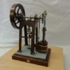
109 forum posts 114 photos | Just to let the readers know that I didn't completely stop working... There is much going on, a planned house move and all the related decluttering ect. If it happens I will have a 7m long workshop (others call it garage) Anyway.
Cylinder block fixed to the bearing blocks. Crankshaft already starting to rust.... My fingers must be acidic... And I am fighting with the album. No matter how I turn the blooming photo it is always at its side.... May be time to update the forum...
Edited By Gerhard Novak on 13/07/2021 21:55:27 Edited By JasonB on 14/07/2021 06:57:39 |
| Gerhard Novak | 14/07/2021 07:07:56 |
109 forum posts 114 photos | Thanks Jason! |


.jpg")
.jpg")


.jpg")

Please login to post a reply.
Magazine Locator
Want the latest issue of Model Engineer or Model Engineers' Workshop? Use our magazine locator links to find your nearest stockist!
Sign up to our Newsletter
Sign up to our newsletter and get a free digital issue.
You can unsubscribe at anytime. View our privacy policy at www.mortons.co.uk/privacy
Latest Forum Posts
- hemingway ball turner
04/07/2025 14:40:26 - *Oct 2023: FORUM MIGRATION TIMELINE*
05/10/2023 07:57:11 - Making ER11 collet chuck
05/10/2023 07:56:24 - What did you do today? 2023
05/10/2023 07:25:01 - Orrery
05/10/2023 06:00:41 - Wera hand-tools
05/10/2023 05:47:07 - New member
05/10/2023 04:40:11 - Problems with external pot on at1 vfd
05/10/2023 00:06:32 - Drain plug
04/10/2023 23:36:17 - digi phase converter for 10 machines.....
04/10/2023 23:13:48 - More Latest Posts...
- View All Topics
Support Our Partners


Shopping Partners
Subscription Offer

Latest "For Sale" Ads
- Reeves** - Rebuilt Royal Scot by Martin Evans
by John Broughton
£300.00 - BRITANNIA 5" GAUGE James Perrier
by Jon Seabright 1
£2,500.00 - Drill Grinder - for restoration
by Nigel Graham 2
£0.00 - WARCO WM18 MILLING MACHINE
by Alex Chudley
£1,200.00 - MYFORD SUPER 7 LATHE
by Alex Chudley
£2,000.00 - More "For Sale" Ads...
Latest "Wanted" Ads
- D1-3 backplate
by Michael Horley
Price Not Specified - fixed steady for a Colchester bantam mark1 800
by George Jervis
Price Not Specified - lbsc pansy
by JACK SIDEBOTHAM
Price Not Specified - Pratt Burnerd multifit chuck key.
by Tim Riome
Price Not Specified - BANDSAW BLADE WELDER
by HUGH
Price Not Specified - More "Wanted" Ads...
Get In Touch!
Do you want to contact the Model Engineer and Model Engineers' Workshop team?
You can contact us by phone, mail or email about the magazines including becoming a contributor, submitting reader's letters or making queries about articles. You can also get in touch about this website, advertising or other general issues.
Click THIS LINK for full contact details.
For subscription issues please see THIS LINK.
Digital Back Issues


Donate

 Register
 Log-in
Model Engineer Magazine
- Percival Marshall
- M.E. History
- LittleLEC
- M.E. Clock

ME Workshop
- An Adcock
- & Shipley
- Horizontal
- Mill

Subscribe Now
- Great savings
- Delivered to your door

Pre-order your copy!
- Delivered to your doorstep!
- Free UK delivery!
All Forum Topics > Stationary engines > A monoblock twin study