Forum sponsored by:

Resurrecting a Stuart 10V
| Colin Heseltine | 27/01/2021 22:51:07 |
| 744 forum posts 375 photos | Many moons ago I bought a built Stuart 10V on Ebay. When it arrived I had a quick look and due to work commitments it got put on one side. I have recently finished two of the Alyn Foundry engines and then saw Dr_GMJN's build of his Stuart 10V and this prompted me to take a look at the one bought a few years ago. I quickly found a few problems. The main bearing bolts on one side were loose, so I tightened them up. Bad move, engine locked up completely. Decided to strip it completely, repair any issues, add a few bits and paint it. The bearings were a major problem, they had been drilled completely out of alignment and needed 25 thou of shims underneath both the flanges on one of the bearings. Also found he had filed the base and the sole plate but not very squarely and the locations of the bolts for the main bearings were all over the place. Some things I would have to live with others would be fixed. New bearings extrusion ordered, along with valve chest cover, drain valves etc. along with small 7ba nuts. Also 5BA and 7BA taps and dies. Whilst waiting for the bits to arrive I started on the steam chest. The slots in the steam valve for the fixing nut were filed but not square and to depth. Also the nut was tapped at an angle. Bit of work with a 3mm slot mill in the Cowells Mill saw the looking a lot better a new nut was fabricated and tapped. The steam chest had also been fitted back to front and had an out of square piece of gauge plate for a cover. By now the ordered parts had arrived and so I machined up the new cover. Started this on the Cowells with a flycutter but it was so chilled around the edges I migrated to the big mill and used a carbide facemill. The cylinder and end covers appeared to have been made quite well and all I did with these was drill the cylinder for drain valves. In one of my other post you can see a fixture plate I made to use initially on this engine. I was able to clamp the soles plate down and facemill the bearing platforms and the standard mounts to get them all level.
Then flipped the casing over and flattened the bottom. I used the same clamp but files the bar so that it would fit between the lower inside of the casting and and not be proud of the top of the base whilst being machined. Colin |
| Colin Heseltine | 28/01/2021 14:15:27 |
| 744 forum posts 375 photos | I felt was going to have difficulty doing the bearings in the normal way by drilling/reaming or boring them in lathe and the turning the bosses down and then trying to fit them onto poorly aligned bolt /stud holes. I elected to fit them to the sole plate first, would rill/ream whilst fitted to the sole plate, then remove and turn bosses to length etc. I started by putting the sole plate in the vice and using the DRO on the Cowells to locate the co-ordinates of all four existing holes.
When I had noted these down I fixed (use this word advisedly) the bearing in place with carpet double sided tape and spotted the holes with a centre drill.
All appeared great so far. Removed the bearings and then used 1mm pilot drill to locate the bearings in vice to drill the holes to 7BA clearance.
One worked perfectly, the rear bearing had moved and one hole was offset by around 1/2 its diameter in two directions. I pondered this for a while. Do I get spare casting and start over or attempt repair. Opted for the repair. The 7BA clearance should be 2.55mm but I had done it at 2.5mm. I turned a short brass pin 2.52mm dia, Loctited the hole and used a punch to drive the pin into the hole then left on a radiator to go off for an hour. Reset the sole plate inthe vice and re-checked the co-ordinates of the holes. This time I was able to use one bolt to hole the bearing firmly in place whilst drilling the 1mm pilot hole. Removed when drilled and opened up to size. Both bearings now fit and are held down by bolts.
Next task to mount vertically on an angle place and drill ream the hole for the crankshaft.. What can go wrong?? Colin |
| Colin Heseltine | 30/01/2021 21:28:25 |
| 744 forum posts 375 photos | Was going to use angle plate and mount the fixture to it, but realised did not need the angle plate, just had to but fixture plate on edge in vice. All was square so centred on the middle of the bearing and went through upper bearing with centre drill and then with 3mm drill followed by 6mm drill. At this point I stopped and fitted long center drill and checked was still on centre in lower bearing.
All was okay so put 3mm and 6m drill through the lower bearing. Followed this with 9.8mm drill through both together. Followed this with 9/32" reamer. Then tried 9/32" drill blank. It fitted.
Removed the bearings and then made small mandrel to hold the bearing by the bore. Used the Cowells lathe and turned the bearings down to final dimensions. Refitted bearings to the sole plate to drill for pair of oil cups. Where are the b....y cups. I had them two weeks ago. Searched high and low through workshop and office. No sign whatsoever. Just about to order some and then decided to make my own. Again used the Cowells lathe as can work in the office in the warm at eye height. When happy with a pair I drilled and tapped the holes in the bearings.
Now to sort a few studs out. Colin Edited By Colin Heseltine on 30/01/2021 21:31:51 |
| Roger Best | 30/01/2021 22:56:03 |
 406 forum posts 56 photos | Great start. Another good advert for not buying someone else's mistakes. |
| Dr_GMJN | 31/01/2021 17:09:16 |
 1602 forum posts | Nice to see another 10V on here. From memory, I did all the boss o/ds, and turned the main bodies to soleplate width on the lathe, but bored the crank hole slightly undersized. The bosses were left long. Then you can drop them into the soleplate, and clamp them firmly in place with a bit of bar. Then drill the mount holes and tighten them down with bolts. This being their finished position. Then mount vertically, aligned with the drill I used to bore them undersize, and made sure I could freely move the head up and down with the drill in the bores. Then in the same setup, finally drill and ream them to finished size. The bosses were then machined to length using the outside of the crank webs to get the right width between them when fitted. Anyway, it looks like yours turned out well. |
| Colin Heseltine | 31/01/2021 20:32:03 |
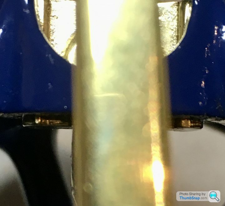
| 744 forum posts 375 photos | Dr_GMJN, My problem was the fact that the bearing mounting bolts were not very well placed which Is why I fitted the bearings and bolted them down before drill/reaming. I have now come across another little problem. Having machined the sole plate flat this has now lowered the cylinder by six or seven thou. The piston now hits the top of the cylinder and prevents the crank from going over centre. I have the "Building a Vertical Steam Engine" book but I think there are a few errors in it. On page 64 it gives the length of the piston rod as 45mm PLUS the 4mm and 6mm threaded portions giving total of 55mm. The plain section on this engine is approx 37mm long. Because of this the piston bottom is 2mm above the inner face of the lower cover. I have a feeling that 45mm in the book is the overall length and the plain section should be 35.719mm (1 13/32" I think I am going to have to shorten the piston rod by around 1.5mm. What is the clearance between the top of the cross-head and the bottom of the piston gland. This looks very close. Again I think I am going to have to take a 0.5mm skim of the top of the cross-head to bring it down to the 10.5mm given in the book. Colin |
| JasonB | 31/01/2021 20:42:25 |
 25215 forum posts 3105 photos 1 articles | It's 1 13/32" on the imperial drawing between Crosshead top and bottom of piston. |
| Colin Heseltine | 31/01/2021 21:11:41 |
| 744 forum posts 375 photos | Jason, Thank for that confirmation. This piston rod is 1.443", so it is 37thou too long. (just under 1mm too long). Plus the piston rod sticks out of the top of the piston by another 10 thou. Another minor issue is that the piston rod gland nut does not screw fully down. The hole is not fully tapped, had a lot of packing in it. But the cross-head is very close. If I can get a tap then can deepen the hole little deeper, put a bit less packing in and the cross-head will then clear. Fixing someone else's poor work takes a little longer than you would think. Colin |
| Dr_GMJN | 31/01/2021 22:59:39 |
1602 forum posts | Colin, the crosshead on mine is close to the gland nut, but then again it depends how far it’s screwed in: I understand now about the bearing holes. I think having read of the amazing powers of JB Weld on here, Id have filled the existing holes with it and started again as if it was untouched metal. You mentioned the steam chest being fitted back to front - mine’s symmetrical. |
| Colin Heseltine | 01/02/2021 22:32:57 |
| 744 forum posts 375 photos | With the mods to the piston rod and the gland nut thread in the bottom cover I temporarily assembled the engine this afternoon. Had a few issues with it locking up when tightening the nuts on the valve chest but eventually sorted this and finally had it running briefly with the air line nozzle blowing into the inlet port.. Gradually speeded up as it freed up. Ran it for about 5 minutes, it was a lot better after squirted some clock oil into the steam chest. Will now sort out the cladding and pipework. Whilst i am painting it I can continue with the reversing gear. Colin
|
| Dave Wootton | 02/02/2021 07:32:00 |
| 505 forum posts 99 photos | Nice work Colin, always interesting to see how others overcome these sort of problems with previous builders work, thanks for posting. I've been sorting out a part built locomotive chassis and posting on here,don't know about you, but I find it stimulates the brain no end trying to work out how to put it right. Like the little fixture for holding the soleplate casting, right up my street!. Keep up the good work and please keep posting. Dave |
| Colin Heseltine | 03/02/2021 16:37:45 |
| 744 forum posts 375 photos |
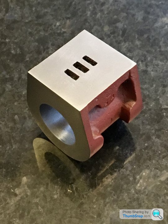
Does anyone have the exact port dimensions for a Stuart 10V or more particularly the depth. The ports on this one I am attempting to resurrect are not cast very well. especially the lh one in the picture above. I am not sure how they are would effect the running of the engine if they are left as is. Is it worth filling the left hand port with JB Weld and then re-machining to the correct size/location. The only dimension I can find anywhere on the plans is the width of 9/32". I assume because the slide valve is recess is 9/32" long then the distance between the outer edge of an inlet port and the outer edge of the exhaust port should also be 9/32". The dimensions I would like to confirm are shown as A,B and C in the drawing below.
The engine turns over quite easily by hand. It does not appear to be tight anywhere. The piston is very free in the bore (maybe too free). BUT It needs a quite high PSI to get it to run. Thanks, Colin Edited By Colin Heseltine on 03/02/2021 16:38:33 |
| Former Member | 03/02/2021 16:44:42 |
| 1085 forum posts | [This posting has been removed] |
| JasonB | 03/02/2021 16:50:02 |
25215 forum posts 3105 photos 1 articles | It's in your 10V book Colin. Who said the old castings were the best Edited By JasonB on 03/02/2021 16:51:03 |
| Former Member | 03/02/2021 17:00:42 |
| 1085 forum posts | [This posting has been removed] |
| Colin Heseltine | 03/02/2021 17:05:40 |
| 744 forum posts 375 photos | Jason, Certainly not on page 22 Fig & cylinder in my book. But my eyes have finally found it on the drawing you sent. Having stared at it for some length of time. The exhaust port is only 3/32". The gap between the lower inlet and the exhaust varied from 1/32" to 1/16" The upper inlet is correct as regards distance from exhaust and its width. What would be recommendation to correct.? Preferably not scrap it. Colin |
| JasonB | 03/02/2021 17:13:30 |
25215 forum posts 3105 photos 1 articles | One option would be to mill out a recess say 1/16" thick to just beyond the area that the steam chest covers and JBWeld in a plate that could be cut from brass. Mill the ports in it first rather than risk having to remove it if something goes wrong while machining in place. |
| Former Member | 03/02/2021 17:14:19 |
| 1085 forum posts | [This posting has been removed] |
| Colin Heseltine | 03/02/2021 17:20:09 |
| 744 forum posts 375 photos | Thanks Jason and Br. Need to have a think? Colin
|
| Dr_GMJN | 03/02/2021 17:28:14 |
1602 forum posts | Posted by br on 03/02/2021 17:00:42:
Posted by JasonB on 03/02/2021 16:50:02:
It's in your 10V book Colin. Who said the old castings were the best Edited By JasonB on 03/02/2021 16:51:03
ME. br
This was my new fangled casting after the port face was fly cut: |


 not 45mm.
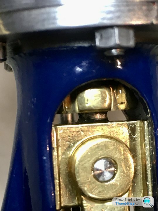


Please login to post a reply.
Magazine Locator
Want the latest issue of Model Engineer or Model Engineers' Workshop? Use our magazine locator links to find your nearest stockist!
Sign up to our Newsletter
Sign up to our newsletter and get a free digital issue.
You can unsubscribe at anytime. View our privacy policy at www.mortons.co.uk/privacy
Latest Forum Posts
- *Oct 2023: FORUM MIGRATION TIMELINE*
05/10/2023 07:57:11 - Making ER11 collet chuck
05/10/2023 07:56:24 - What did you do today? 2023
05/10/2023 07:25:01 - Orrery
05/10/2023 06:00:41 - Wera hand-tools
05/10/2023 05:47:07 - New member
05/10/2023 04:40:11 - Problems with external pot on at1 vfd
05/10/2023 00:06:32 - Drain plug
04/10/2023 23:36:17 - digi phase converter for 10 machines.....
04/10/2023 23:13:48 - Winter Storage Of Locomotives
04/10/2023 21:02:11 - More Latest Posts...
- View All Topics
Support Our Partners


Shopping Partners
Subscription Offer

Latest "For Sale" Ads
- Reeves** - Rebuilt Royal Scot by Martin Evans
by John Broughton
£300.00 - BRITANNIA 5" GAUGE James Perrier
by Jon Seabright 1
£2,500.00 - Drill Grinder - for restoration
by Nigel Graham 2
£0.00 - WARCO WM18 MILLING MACHINE
by Alex Chudley
£1,200.00 - MYFORD SUPER 7 LATHE
by Alex Chudley
£2,000.00 - More "For Sale" Ads...
Latest "Wanted" Ads
- D1-3 backplate
by Michael Horley
Price Not Specified - fixed steady for a Colchester bantam mark1 800
by George Jervis
Price Not Specified - lbsc pansy
by JACK SIDEBOTHAM
Price Not Specified - Pratt Burnerd multifit chuck key.
by Tim Riome
Price Not Specified - BANDSAW BLADE WELDER
by HUGH
Price Not Specified - More "Wanted" Ads...
Get In Touch!
Do you want to contact the Model Engineer and Model Engineers' Workshop team?
You can contact us by phone, mail or email about the magazines including becoming a contributor, submitting reader's letters or making queries about articles. You can also get in touch about this website, advertising or other general issues.
Click THIS LINK for full contact details.
For subscription issues please see THIS LINK.
Digital Back Issues


Donate

 Register
 Log-in
Model Engineer Magazine
- Percival Marshall
- M.E. History
- LittleLEC
- M.E. Clock

ME Workshop
- An Adcock
- & Shipley
- Horizontal
- Mill

Subscribe Now
- Great savings
- Delivered to your door

Pre-order your copy!
- Delivered to your doorstep!
- Free UK delivery!
All Forum Topics > Work In Progress and completed items > Resurrecting a Stuart 10V