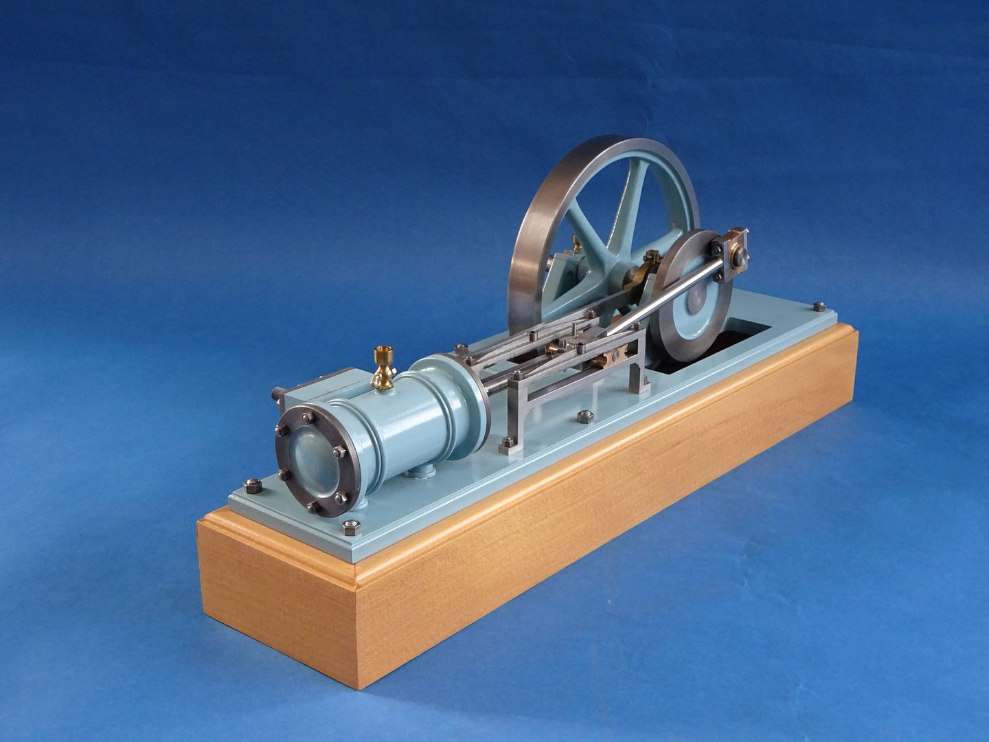
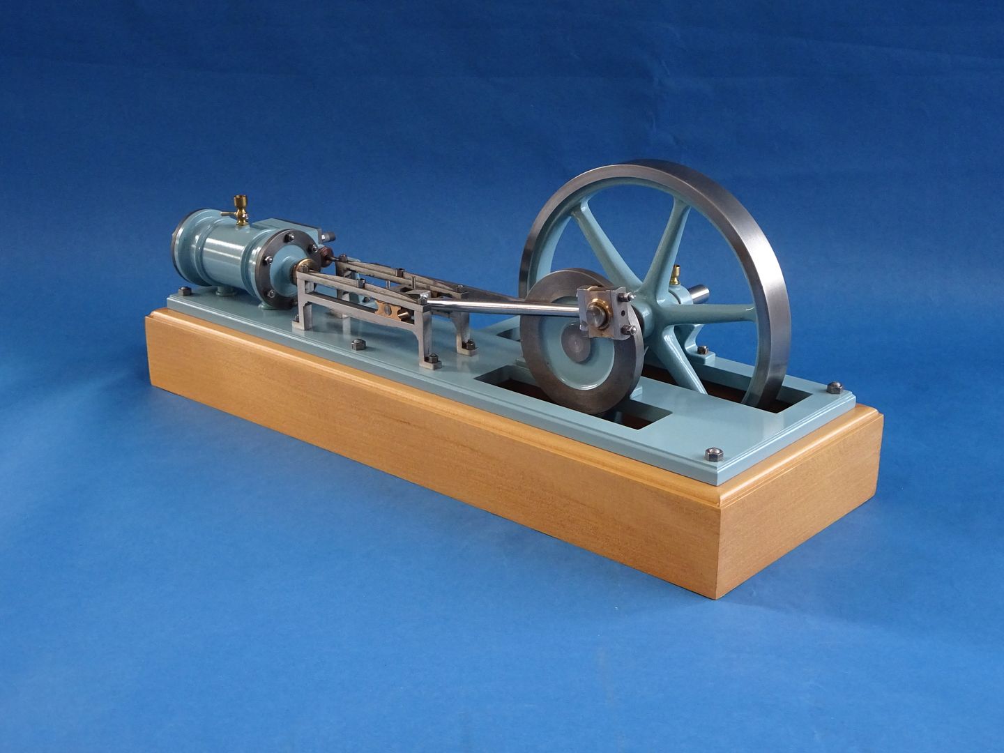
Thompstone Engine
A thread to accompany the build series in ME

| JasonB | 20/01/2021 18:52:21 |
25215 forum posts 3105 photos 1 articles | As ME 4662 has just hit the digital door step this thread can now be made active and will accompany my build series about my version of a horizontal mill engine originally described by S. L. Thompstone in an early edition of ME from 1901 This thread is for anyone who may have queries or comments about the engine such as alternative materials or construction methods to suit what tools you have. Additionally I will post extra photos that would have possibly packed out the article too much but that may still be of use to those building the Engine. Martin is kindly publishing in consecutive magazines so that the build won't be spread over too long a period. For those that have not seen my previous posts of the engine here is a video of it running of 2-3psi of air to wet your appetite and hopefully tempt you to give it a go. Edited By JasonB on 06/04/2021 16:04:23 |
| JasonB | 06/04/2021 16:23:15 |
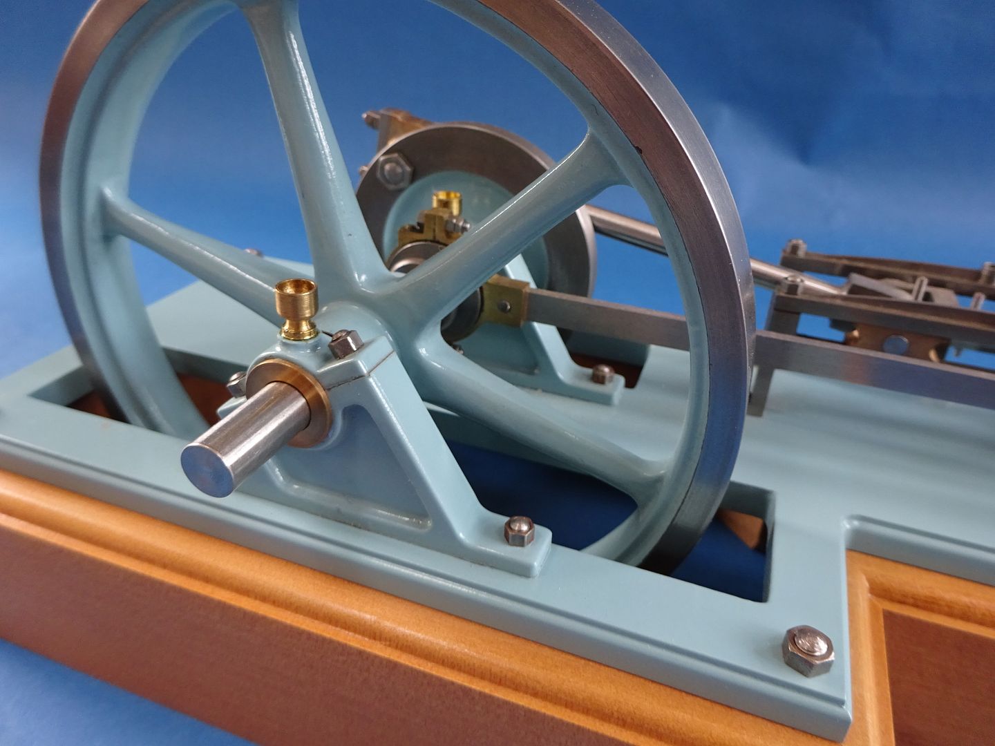
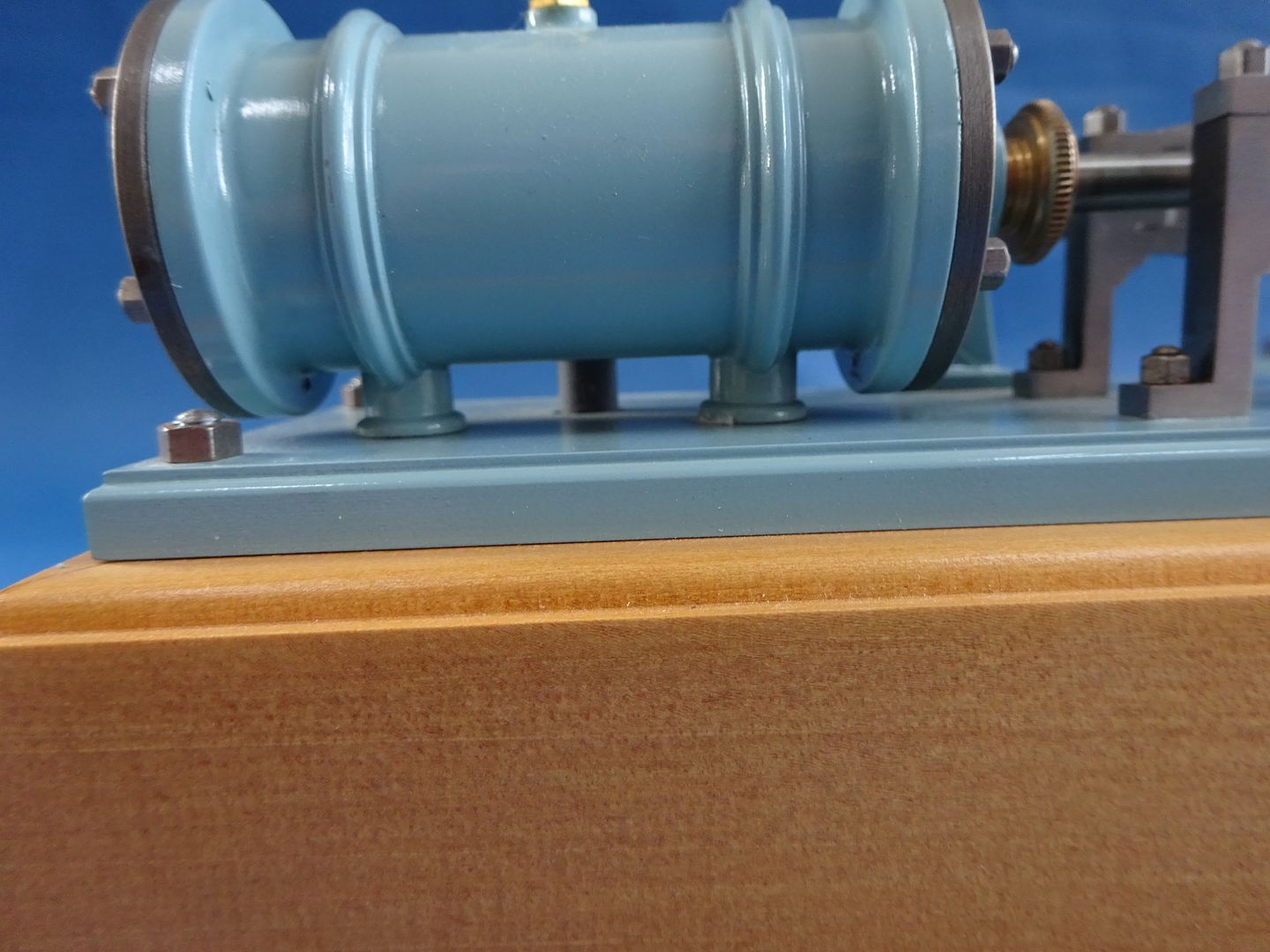
25215 forum posts 3105 photos 1 articles | Although I always suggest that a prospective builder go through the drawings to work out what materials they may need as this is a good way to familiarise yourself with the design and how you will need to hold parts to machine them there are those who like a bill of materials one of which can be downloaded from here. Note that these are the minimum overall sizes so allowance should be made for cutting, parting and holding to suit your own machines and methods. I have also listed what fixings will be needed, these are metric fasteners with small size hexagon heads available from Polly Engineering in the UK or direct from GHW in Germany. as they look nicer than commercial metric fixings. I would also suggest a few metric cap head screws are worth purchasing as these are more user friendly during construction where things will be assembled and taken apart several times. Somewhere like Model fixings do small packs and their ball ended hex drivers are a lot easier to use than a standard hex key. M2.5 and M3 should be sufficient for the cap heads. Here are a few more photos of my finished engine which should give an idea of what's to follow. |
| JasonB | 06/04/2021 20:07:52 |
25215 forum posts 3105 photos 1 articles | This is the drawing that was originally on ME issue No 49 |
| JasonB | 07/04/2021 07:45:52 |
25215 forum posts 3105 photos 1 articles | General Arrangements in B&W and colour. |
| Luker | 07/04/2021 07:58:15 |
230 forum posts 172 photos | Hi Jason, I read part one yesterday, enjoyed the write-up and I am looking forward to the rest of the series! That is one fine looking engine |
| Ferrum | 07/04/2021 14:59:29 |
| 23 forum posts | Hi Jason, The engine looks beautifully proportioned. I will follow the series and expect that I will learn a lot from your techniques. Ron |
| JasonB | 07/04/2021 16:32:56 |
25215 forum posts 3105 photos 1 articles | Thanks for the comments, Luker I will wait for my paper copy to have a read of your 3D printed pattern article. It is quite a nicely proportioned engine, having just done a Stuart Victoria which has almost the same bore and stroke the Stuart seems quite agricultural in some areas as well as being considerably larger. I went through the bill of materials last night and priced it up allowing for 300mm lengths of the smaller sections and the bigger bits in the nearest 25mm increments and allowing £25 for a flywheel casting the materials came in at £101.00. Allowing a further £25-30 for fixings etc as they tend to come in packs of 50 that still makes it about 1/3rd the cost of a set of Victoria castings with the added bonus that fabricating and cutting from solid will give you more workshop time for the lower outlay so another win win situation. If going for the JB Weld option over silver solder then you could actually use cast iron for all the cylinder parts and that would be a bit of a saving over bronze/brass. |
| Paul Horth | 14/04/2021 16:53:08 |
| 69 forum posts 18 photos | Hello Jason, I have a few questions about this model design by Thompstone, and the full size engine which it might have been based on. Do you have an idea of the scale that Thompstone intended? It looks like quite a small engine, maybe a bore of 1 foot, or smaller than that, having a screwed gland? I can't make out where the exhaust connection is. I would be interested in your opinion of some of the features which Thompstone has included.
Please understand that these comments are not meant as criticisms, I am just curious about the full size design features which I know little about. Paul |
| JasonB | 14/04/2021 18:40:40 |
25215 forum posts 3105 photos 1 articles | Hi Paul, No problem discussing aspects of the design. Thompstone does not say that the engine is based on any specific prototype, in fact he just presents it as a "Model Horizontal Engine. Since I first saw it I have always pictured it as a small workshop engine rather than anything large so bore would be in the region of 3 to 4 inches which gives a scale of around 1/3rd to 1/4. 1. It's a bit difficult to make out what he is describing in the text (I'll post that later) and the drawing does not help too much. The part I have arrowed in red seems to be shaded as if to represent a curved or rounded surface but there is not outer edge, I would have expected a line down from the end of the cylinder possibly? The way the bottom nuts are visible suggests that whatever support is to the valve chest side of ctr line ? He says that the exhaust has back nuts which make the cylinder fixing rigid so that may be acting as a third leg? I have assumed that the part arrowed blue in the middle is the exhaust going down into the base. So with those details not being clear I took a bit of artistic licence and used the two round feet which seemed right centred on the bands and just dropped the exhaust down into the base. I'm not keen on the angle brackets that the basic Stuart Victoria uses but it would not be out of keeping to add wider feet in the style of "Princess Royal" or similar which could easily be substituted for my round feet. The Victoria was based on another workshop engine of 5" bore so again quite a small prototype.
2. The decorative cast rings seem quite common when looking at other workshop and generally small engines and there may be even more with them but hidden from view under cladding. If you have a look at these three pages of horizontal engines on Preston's website you can see several examples of one or two bands around the cylinders.
3. Again there are several of the engines on Preston's that have a similar oil or fat pot centrally mounted on the cylinder so reasonable to assume it's not out of place on an engine like this.
4. I'm not sure if there is a specific reason that the split line of the main bearings is angled like this. On an IC engine they tend to be angled the other way which I have always assumed is to better resist the forces during the ignition stroke but as our steam engine is double acting that can't be why. Another thought is that by angling the split line of the bearing it puts the joint above and below the main angles of thrust as the piston moves back and forth which means an uninterrupted oil fil on the surface of the bearing where the load is greater. But I'd welcome any other comments on this one. It's something you see on most sizes of engine, from the small workshop ones at Preston's, Tangyes used it quite a bit on their various engines not just the popular one that gets modelled but also ones like their "colonial" and right upto some of the larger Corliss engines by various makers. Edited By JasonB on 14/04/2021 18:43:28 |
| JasonB | 14/04/2021 19:11:37 |
25215 forum posts 3105 photos 1 articles | I just remembered that I did sketch out a simplified version with crosshead guides like a Victoria and also went with a different foot arrangement for the cylinder. Edited By JasonB on 14/04/2021 19:12:05 |
| Paul Horth | 15/04/2021 13:43:36 |
| 69 forum posts 18 photos | Jason, Thank you for your helpful explanations. And thanks also for the link to Preston Services. I didn't know that such small engines were produced commercially.Nor did I realise the high prices they can get. You would need after all a decent sized boiler to run one of these (with its certificate and insurance), and a pump, feed tank, water treatment etc and the space to keep all this kit. That's why I'll stick with models for my steam kicks.
Paul
|
| Ron Laden | 15/04/2021 15:57:55 |
2320 forum posts 452 photos | Hi Jason, don't want to butt in other to say the cylinder looks every bit a casting, you certainly have it down to an art producing would be castings from bar stock. I wondered could the rings on the larger full size engines be there for stiffness/rigidity maintaining size and shape on a part like a cylinder which heats and cools, maybe not just a thought. Ron |
| JasonB | 15/04/2021 16:20:29 |
25215 forum posts 3105 photos 1 articles | Hi Ron, don't feel you are butting in, the more the merrier. Yes that is the only practical reason that I can thing of the bands being used to ass strength which may allow the rest of the cylinder side wall to be cast a bit thinner. Here is the text that went with the GA drawings I posted last week |
| JasonB | 15/04/2021 18:19:12 |
25215 forum posts 3105 photos 1 articles | I think I should buy a lottery ticket this week as what are the chances of this turning up on e-bay just as I've started this series. Looks to be based on the same original design, cylinder and the crosshead guides are right just the simpler upright bearing housings let it down. While I'm on does anyone have a copy of an early ME, Vol 6 No 69 as there is a mention of castings for this engine in it.
|
| Weary | 15/04/2021 20:22:01 |
| 421 forum posts 1 photos | Jason, and others, of course, Re: period castings for Thompstone Engine;: Model Engineer, Vol VI, No.69, March 15 1902, page 144, under heading 'Amateurs Supplies', text reads: Model Horizontal Engine Castings Readers of The Model Engineer will hardly need an introduction to the work of Mr S. L. Thompstone, some of it already having been published in these pages. A neat list, which he is issuing post free, on application, illustrates a model horizontal engine which is made in two sizes. Those who require castings of this type of engine should make application to Mr Thompstone, Nelson Street, Broughton, Manchester. End of text.
Regards, Phil.
|
| JasonB | 15/04/2021 20:27:06 |
25215 forum posts 3105 photos 1 articles | Thanks for that Phil, interesting to see it was being made available in two sizes |
| Ron Laden | 17/04/2021 07:13:22 |
2320 forum posts 452 photos | Morning Jason, I watched the video again I really do like the long stroke especially when running slowly, nice sounding engine also. I see from the Thompstone text that the engine is just 1/16" shy of being under square by 2 to 1. Is that about as long a stroke you see on stationary engines or can they be longer. Ron |
| Nigel Graham 2 | 17/04/2021 11:40:27 |
| 3293 forum posts 112 photos | A handsome engine! Paul - though freelance this design is very much in the spirit of any number of small horizontal and vertical engines produced by any number of companies in the late-19 - early 20C; ranging in power down to about 1HP. Though often called "mill-engines" they were the ubiquitous industrial prime-movers of their day, for all manner of applications. Some of the small ones were portable power-packs, combining an inverted-vertical (cylinder at the top) engine with a vertical boiler, on a rather crude horse- or man- pulled trolley. Their buyers were typically farmers, builders, timber-merchants, quarriers and the like. A horizontal stationary-engine of the genre, probably around 10NHP rating and built by Hindley for driving water-supply pumps, is preserved in running order in the waterworks museum at Sherborne, N. Dorset; open on some Summer weekends. Other examples in different forms are to be seen at Weston Zoyland [fenland] Pumping Station. ' Ron's query: Bore : Stroke = almost 1 : 2. Thompstone had it right, typical for such horizontal and vertical engines, according to a book I have published in 1911. The table is for "Strong" engines from 3 to 30 Nominal Horsepower. By the same table, a short-stroke "Light" version (1.5 - 16 NHP) was commonly over-square, about 1 : 0.8 . I am not sure what the adjectives meant in this context! ' My query - The rings round the cylinder were common practice so look right here, but I wonder if they were purely "ornamental" or also functional in some way - reinforcing perhaps, to support cladding where fitted, or to prevent cracking from the contraction stresses in cooling. (The curly spokes on some cast wheels was not prettiness but that anti-cracking precaution.) Some engines were quite highly ornamented - think of the giant beam-engines at Kew for example- but that would have added to the manufacturing cost. Still, places like Kew Bridge Pumping Station were among the prestige public-service projects of their day, so designers reflected that. Would it have been done for more modest machines though, more impressive in looks than are electric motors, but doing essentially the same thing? Anyway, it's a very elegant design, good to see revived. Edited By Nigel Graham 2 on 17/04/2021 11:41:28 |
| Nigel Graham 2 | 17/04/2021 11:58:27 |
| 3293 forum posts 112 photos | Adding to above.... Looking at the photos again, though the Thompstone engine (and Jason's working of it) look right, the e-Bay one seems to have an under-length connecting-rod. Though less definitive, that book I cite suggests Con-rod centres : Stroke at least 2 : 1 (about 27º max. angle); up to about 4 : 1. The lower value particularly for marine engines, for headroom and low centre of gravity needs. This engine's proportion is 2.6 : 1. It looks as if Thompstone used contemporary reference works published for the designers of the full-size engines. even if not modelling an actual engine. |
| JasonB | 19/04/2021 19:54:42 |
25215 forum posts 3105 photos 1 articles | Thanks for the Imput nigel. With a Bumper 5 pages on this engine in 4663 that has just been made available digitally there are a few extra photos that I did not include in the article that may still be of use to anyone thinking of having a go. Photo 10AThe port face having been milled flat and down to finished size and the stud holes tapped
Photo 14A. View of underside of the cylinder showing tapped exhaust outlet and feet
Photo 14B. End view of cylinder showing milled notch through to steam passage
Photo 15A. Two pieces of cast iron being milled to overall size for valve chest and cover, who said machining CI needs to be dusty when you can get nice swarf like that. Photo 16A. Using a round nosed tool to form the neck of the valve chest's gland boss Photo 20A. Boring the recess in the cylinder front cover to clear the piston lock nut. |
Please login to post a reply.
Want the latest issue of Model Engineer or Model Engineers' Workshop? Use our magazine locator links to find your nearest stockist!
Sign up to our newsletter and get a free digital issue.
You can unsubscribe at anytime. View our privacy policy at www.mortons.co.uk/privacy
- *Oct 2023: FORUM MIGRATION TIMELINE*
05/10/2023 07:57:11 - Making ER11 collet chuck
05/10/2023 07:56:24 - What did you do today? 2023
05/10/2023 07:25:01 - Orrery
05/10/2023 06:00:41 - Wera hand-tools
05/10/2023 05:47:07 - New member
05/10/2023 04:40:11 - Problems with external pot on at1 vfd
05/10/2023 00:06:32 - Drain plug
04/10/2023 23:36:17 - digi phase converter for 10 machines.....
04/10/2023 23:13:48 - Winter Storage Of Locomotives
04/10/2023 21:02:11 - More Latest Posts...
- View All Topics
- Reeves** - Rebuilt Royal Scot by Martin Evans
by John Broughton
£300.00 - BRITANNIA 5" GAUGE James Perrier
by Jon Seabright 1
£2,500.00 - Drill Grinder - for restoration
by Nigel Graham 2
£0.00 - WARCO WM18 MILLING MACHINE
by Alex Chudley
£1,200.00 - MYFORD SUPER 7 LATHE
by Alex Chudley
£2,000.00 - More "For Sale" Ads...
- D1-3 backplate
by Michael Horley
Price Not Specified - fixed steady for a Colchester bantam mark1 800
by George Jervis
Price Not Specified - lbsc pansy
by JACK SIDEBOTHAM
Price Not Specified - Pratt Burnerd multifit chuck key.
by Tim Riome
Price Not Specified - BANDSAW BLADE WELDER
by HUGH
Price Not Specified - More "Wanted" Ads...
Do you want to contact the Model Engineer and Model Engineers' Workshop team?
You can contact us by phone, mail or email about the magazines including becoming a contributor, submitting reader's letters or making queries about articles. You can also get in touch about this website, advertising or other general issues.
Click THIS LINK for full contact details.
For subscription issues please see THIS LINK.
Model Engineer Magazine
- Percival Marshall
- M.E. History
- LittleLEC
- M.E. Clock
ME Workshop
- An Adcock
- & Shipley
- Horizontal
- Mill
Subscribe Now
- Great savings
- Delivered to your door
Pre-order your copy!
- Delivered to your doorstep!
- Free UK delivery!


![20210407_141447[1].jpg 20210407_141447[1].jpg](/sites/7/images/member_albums/44290/892023.jpg)


 Register
 Log-in


