Forum sponsored by:

Mystery boiler
Live steam G1
| Martin Botting 2 | 10/09/2020 09:47:08 |
 93 forum posts 20 photos | Greetings fellow subscribers.
I wonder if there are any readers who could help? Being a proficient maker of swarf from perfectly good metal I like a magpie bought 3 boilers from a chap a while back and they have been collecting dust in the workshop ( next to the faceplate) I have worked out that two are designed around the Gauge1 “Project” boiler but one is slightly longer. The third and largest is this. A few dimensions: Barrel length: 17cm X 5.5cm Dia Fire box 8cm internal grate 6 X 5.7cm 7X 3/16th ID tubes 1X 5/16 id (superheater?) tube. A wide grate firebox with an upright throat plate.
I have had a look inside as best I can with my usb down the throat camera (dont ask) and the firebox crown stays are of the girder type and are silver soldered to the top of the wrapper.
What holes there are in bushings or threaded in ME or Bsw thread forms. There is room in the back head for a hollow stay and a corresponding hole in the front tube plate, This threaded 5/16 x40 but is partly blocked by the firebox crown plate!
There is a silver soldered hex plug on top of the barrel over the backhead plate thats drilled with a passage to the barrel. The two 7/32x40 holes on the left of the backhead are to my mind for a water gauge but looking at how tall the inner firebox is it would only be the top 1/4” of the glass till the crowmplate becomes exposed. There is some charing on the inside of the firebox which might indicate coal firing and the hinged firehouse door would also intimate the same
I will make up some plugs and get the club boiler inspector to have a go at them before making my mind up what should go round them.
But any help with the design and more information on what it might be for would be helpful. Many thanks in advance. Martin |
| Martin Botting 2 | 10/09/2020 09:48:31 |
93 forum posts 20 photos |
|
| Nigel Graham 2 | 12/09/2020 00:01:55 |
| 3293 forum posts 112 photos | Hmmm. I think a boiler tester might worry about one or two awkward points. Such as - Holes not provided with bushes, but tapped straight into the fairly thin copper, and one encroaching on the flange bend - poor practice even in small scales, but I think some of LBSC's designs specified that. BSW is not a good choice of thread for small boiler-fittings - BSP or BSF perhaps, but Whitworth is very coarse for such purposes. What is that "bubbly" material around what does seem the hole for the hollow stay in the front tube-plate? Has something been removed? The big blob of solder by the super-heater flue draws attention to the joints themselves, but they may be sound. The inner firebox enforcing a high and narrow water-level range, and obstructing what may be the hollow-stay's route, is a bit odd. Where does / do the feed clack(s) fit? It looks as if this boiler has been used but later removed from the loco, for some reason unknown but possibly involving modifications to it (the boiler). I cannot identify the locomotive but the boiler shape and dimensions suggest 2.5 " gauge, 4- or 6-, perhaps 8-, coupled wheelbase, possibly LNER? I would advise a preliminary dry inspection before going as far as the hydraulic test; but be prepared to be asked for a drawing I assume you don't have. ==' If it's any comfort I have seen worse - a 3.5 " -gauge LNER-pattern boiler, newly and beautifully made to the drawing by a retired, professional coppersmith... Only the drawing, a low-quality photocopy carrying neither designer's nor publisher's name, had specified virtually no stays. Consequently the builder's own preliminary hydraulic test had crushed the inner firebox, but without rupture and he had not noticed the damage obvious to us when we turned the boiler over. It destroyed his first foray into model-engineering, before he had learnt much about steam engines. Introduced by a club member who knew him at work, he had brought the boiler with him for testing on his first visit to us. Last, too, sadly: we never saw him again. For some reason he would not tell us the source of the faulty, anonymous drawings. We wanted to know so we could send a letter to ME, warning of its existence.
|
| Paul Lousick | 12/09/2020 02:03:32 |
| 2276 forum posts 801 photos | Because you have not built the boiler and do not have certification for materials and its construction, I would talk to a boiler inspector befor you proceed any further. It would be a waste of time and money if you cannot get it approved. Paul. |
| Martin Botting 2 | 12/09/2020 09:00:45 |
93 forum posts 20 photos |
Edited By Martin Botting 2 on 12/09/2020 09:02:31 |
| Martin Botting 2 | 12/09/2020 09:03:14 |
93 forum posts 20 photos | Thank you for your input, The "bubbly stuff" is some kind of sealant I think, not tasted it yet... I was thinking down the lines of LNER or LBSCR Atlantics, but the throat plate it vertical. on the left of the backhead low down near the piled up plates on the sides and copper square fore and aft of the foundation ring is a bushed hole I would guess for the clack. as you say the club boiler inspector will no doubt do his duty and suggest I turn it into a dust collector. from what I can see inside there is no scaling on the firebox crown or the tubes. I am still mystified how the steam was regulated! anyway I will take it along to the club with the other two boilers of the Project design and have them looked at when this virus thing has passed. |
| Bazyle | 12/09/2020 09:37:23 |
 6956 forum posts 229 photos | Don't be pu toff. Bushes can be added, material provenence is necessary for welded steel but not essential for copper provided you can see the thickness is not silly thin. It is a bit odd that the front vacant blower hole is not in line with anything on the backhead, and the wider tube looks too thin for a superheater flow and return. The blanking plugs seem to be asymetrical - did the builder get it wrong and then have to kludge the fittings, Down to your initial question of what loco it is for as it is longer than a Project which is an 0-6-0 you can surmise that it is either a longer tank loco,0-6-2 for example not too common in G1, or a tender loco which would be more likely. It is not a Belpaire nor flared firebox so that excludes a few ptototypes and the depth of the firebox doesn't give much room for a trailing axle. So perhaps a 4-6-0 and the most common of those is Doris. |
| Nick Clarke 3 | 12/09/2020 11:16:29 |
 1607 forum posts 69 photos | Posted by Nigel Graham 2 on 12/09/2020 00:01:55:
Hmmm. I think a boiler tester might worry about one or two awkward points. Such as - Holes not provided with bushes, but tapped straight into the fairly thin copper, and one encroaching on the flange bend - poor practice even in small scales, but I think some of LBSC's designs specified that. BSW is not a good choice of thread for small boiler-fittings - BSP or BSF perhaps, but Whitworth is very coarse for such purposes.
I am wondering if this is an LBSC design, or at least one influenced by him - the tapped plates for fittings and single hole for top feed are distinctive. It revisits the dilemma imposed by our boiler rules which are primarily concerned with testing rather than design. If a drawing could be found and the tapped holes for fittings were shown on it then a boiler tester would only need to be interested in their condition and could not fail the boiler for not having bushes - even though this is the far better way of going about things. However if no drawing is available it needs to be designed (including calculations) and made to best practice as it stands today to pass. |
| Paul Kemp | 12/09/2020 11:36:05 |
| 798 forum posts 27 photos | You could always produce an "as built" drawing and some supporting calculations. Given the size I can't see you will be looking for a working pressure of 150psi so it really comes down to whether the inspector chosen is a pragmatic practical fellow or a rules is rules type of guy. Paul. |
| Nigel Graham 2 | 13/09/2020 23:45:17 |
| 3293 forum posts 112 photos | I have before me my copy of the latest edition of The Scriptures (Orange-on-White, a.k.a. The Boiler Test Code 2018)... This is not verbatim but a précis to suit what we have here. "Shall" is a legal word meaning exactly what it says: 5. Design Verification. This section clarifies that a boiler not to a recognised design must be accompanied by the relevant drawings and by calculation or well-proven example, evidence of adequate strength of design and materials. The drawings or accompanying text shall show the Working Pressure - if that is not available it has to be calculated and the calculations verified. The boiler shall treated as a new design, so given an "Initial hydraulic shell pressure-test", without cladding, to 2 X WP. === So in this case, you would need and can only produce, as Paul Kemp says, a drawing of the boiler as it is, and use the regular calculations to assess its own, sensible working-pressure guided by typical for the scale of the locomotive. As its history is unknown it would be treated as a "new" boiler and given the initial 2 X WP hydraulic test - and when the loco is finished, the first regular 1.5 X WP hydraulic, and the steam-accumulation, tests. Though that section does not say refer to materials, you do not need traceability documents for an owner-built copper boiler's materials.
=== You need to know the boilers Bar.litre capacity - simple enough once you know the working-pressure. Fill the boiler completely using a measuring jug, multiply that amount of water in litres by the WP in Bar. A boiler also needs an ID number. You can use your own, but the Orange-on-White Book recommends following your Club's federation's system. # NB: Club Boiler Inspectors are not duty bound to test a boiler full-stop. They will do their best and a happy boiler admirer is one who has just passed a boiler for service, but the Test Code makes clear that he can, and should, refuse to test a boiler he feels outside of his experience. Obviously he can also fail a boiler even just on dry examination, but has to give the refusal and explanation in writing. There is a space on the Certificate for this, though to be honest if this was a boiler not yet on the books and unlikely to be made serviceable in the near future, I'd probably just apologise and refuse it verbally, though still explain why of course.
I suggest, if you haven't already, obtaining a copy for yourself of The Boiler Test Code 2018 , so you know what is expected, in detail. It is not the best of technical documents as the applicable clear road ahead is not immediately obvious, but it does contain all the information you and the Boiler Inspector need. Just as well because the Certificates are not the simplest of forms to complete! You can also follow the instructions to ensure by a preliminary test, the boiler is ready for its official test. If you do I would suggest going to WP only first, hydraulically of course and in gentle stages, and only if that's satisfactory, to 1.5WP maximum. Leave the 2WP to the proper test. +++ Another thought on the apparent soot. Soot or oxide? I wonder if that is actually from the silver-soldering, not from any firing. |
| Martin Botting 2 | 14/09/2020 07:05:03 |
93 forum posts 20 photos | Nigel. Many thanks for that information. Lots to digest there and some day after I have stubbed my toe enough on the thing I may reconsider putting it to some use, but on looking at it the other two of more simpler design would find a home between the frames of a G1 loco. Much appreciated comment has come from forum members and with a great wealth of knowledge. Along with its two dust collecting chums it has taken a bath in the citric acid and a good look around leaves me thinking that while it would provide plenty of adhesion weight to a loco the thing would be a poor steamer due to the small steam space above the crown. When it comes to the inspection of boilers I am taken to the joke of the parachutist that has a failed Shute and reserve hurtling toward the earth sees a charred man coming in the opposite direction "do you know anything about parachutes?" 'NO... do you know anything about boilers?" comes the reply.
|
| Nigel Graham 2 | 15/09/2020 01:42:36 |
| 3293 forum posts 112 photos | Thank you! Looking at the photos again, it seems actually well made, but not very well designed, as if by someone not versed in the more subtle aspects of loco boilers. One puzzle, as you mention, is how the original builder intended to get the steam to the super-heater, which with only one element of a pair of rather small tubes, would act as a pretty efficient restrictor. Normally there would be 3 or 4 super-heater flues and these are usually above the fire-tubes. Now, there is no intrinsic reason that I know of, why a miniature boiler could not have the super-heater below the other tubes provided there is room behind the chimney and blast-pipe for it, but it's normally at the top to suit the steam-pipe from the regulator in the dome. Some models do use external regulators, either hidden in the smoke-box or rather inelegantly on the back-head, the latter usually on narrow-gauge locos where bolting bits on the outside is a bit more prototypical. Yet your boiler shows no sign of any internal steam-pipe, nor of any external regulator mountings. I can only think its designer had an external pipe in mind, difficult to hide on a standard-gauge outline loco in British railway practice, though I suppose it could be hidden under the cladding. The hole on the lower corner of the back-head: I'd assumed it to be for a blow-down valve, though It could have been intended for a feed clack. Oh to know what loco is being replicated! **** I think a lot of club boiler-inspectors would be unhappy to certify this boiler, whose main problem may be that over-high internal fire-box. They may well want at least, the threaded holes fitted with silver-soldered bronze bushes, unless they can accept a design directly comparable to known boilers using direct threads. Probably, your best course of action if you decide to use it, would be to write down what work needs doing to it, and its working-pressure and the method you used to find that. Then before cutting any metal, show the boiler inspector both the unit itself and that information, and ask his advice. Note that the initial shell test is just that - the full certification needs it pass a hydraulic test in working condition, and a steam-test to verify the safety-valves, pressure-gauge and feed arrangements. ' I wonder how many other miniature locomotive boilers there are out there, all forlornly awaiting identifying and pairing with the rest of the intended machine in the hope that the Great God PER will bestow his blessings upon them? Looking at the second-hand traders' exhibition stands I reckon you could almost build a somewhat quirky but effective engine around the once-high hopes languishing in the dream-catcher trays of assorted wheels, possibly-identified boilers, unidentified cylinders, unidentifiable bits, rusty castings and grubby frames.. |
| Martin Botting 2 | 16/09/2020 07:20:15 |
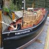
93 forum posts 20 photos | I dropped Barrett steam models a line with the same pictures, and the same question and got a very nice email from Steve Barrett The photo I included at the start of this question may have been misleading in that the the firebox wrapper is tapered. and as Steve pointed out it would never sit between the fames of anything G1 come to that anything less than 3" gauge would not work.
|
| Martin Botting 2 | 16/09/2020 07:20:26 |
93 forum posts 20 photos | I include the very detailed email fromMr Barrett Hi Martin, Interesting. In general, the diameter points to a large boilered G1 loco. The parallel sided firebox points away from G1 pacifics with Wootton style like a duchess. The tapped copper platework (without bushes) indicates early designs from LBSC, a practice that is now frowned upon. The width of the firebox would’nt fit between any G1 wheelset at 40mm back to back – ruling out all designs. However. Small 3 ½” gauge locos like Titch, Rob Roy, Molly may be a better bet. Or maybe a 2 ½” something – but again watch the frame spacing over the firebox. Bottom left bushed hole for clack feed . Watergauge was probably where you suggested, on the left. But using the upper hole for the bottom of glass. The gauge top fittings would be taken from the hex fitting on top. Top hex plug for a takeoff manifold to feed water gauge top, pressure gauge, blower control. Blower control outlet to pass through hollow stay to smokebox and terminating with a jet up the chimney. Possibly silversoldered in place by accident if it was intended for a manifold. Top centre would be for the regulator which then should appear top centre on smokebox tubeplate (not yet drilled ?). 5/16 ID tube could be used for a slim spearhead superheater element but is really to small diameter to be of use. A few turns of the steam main coiled in the smokebox will probably suffice. Best of luck ! Steve Barrett
|


Please login to post a reply.
Magazine Locator
Want the latest issue of Model Engineer or Model Engineers' Workshop? Use our magazine locator links to find your nearest stockist!
Sign up to our Newsletter
Sign up to our newsletter and get a free digital issue.
You can unsubscribe at anytime. View our privacy policy at www.mortons.co.uk/privacy
Latest Forum Posts
- *Oct 2023: FORUM MIGRATION TIMELINE*
05/10/2023 07:57:11 - Making ER11 collet chuck
05/10/2023 07:56:24 - What did you do today? 2023
05/10/2023 07:25:01 - Orrery
05/10/2023 06:00:41 - Wera hand-tools
05/10/2023 05:47:07 - New member
05/10/2023 04:40:11 - Problems with external pot on at1 vfd
05/10/2023 00:06:32 - Drain plug
04/10/2023 23:36:17 - digi phase converter for 10 machines.....
04/10/2023 23:13:48 - Winter Storage Of Locomotives
04/10/2023 21:02:11 - More Latest Posts...
- View All Topics
Support Our Partners


Shopping Partners
Subscription Offer

Latest "For Sale" Ads
- Reeves** - Rebuilt Royal Scot by Martin Evans
by John Broughton
£300.00 - BRITANNIA 5" GAUGE James Perrier
by Jon Seabright 1
£2,500.00 - Drill Grinder - for restoration
by Nigel Graham 2
£0.00 - WARCO WM18 MILLING MACHINE
by Alex Chudley
£1,200.00 - MYFORD SUPER 7 LATHE
by Alex Chudley
£2,000.00 - More "For Sale" Ads...
Latest "Wanted" Ads
- D1-3 backplate
by Michael Horley
Price Not Specified - fixed steady for a Colchester bantam mark1 800
by George Jervis
Price Not Specified - lbsc pansy
by JACK SIDEBOTHAM
Price Not Specified - Pratt Burnerd multifit chuck key.
by Tim Riome
Price Not Specified - BANDSAW BLADE WELDER
by HUGH
Price Not Specified - More "Wanted" Ads...
Get In Touch!
Do you want to contact the Model Engineer and Model Engineers' Workshop team?
You can contact us by phone, mail or email about the magazines including becoming a contributor, submitting reader's letters or making queries about articles. You can also get in touch about this website, advertising or other general issues.
Click THIS LINK for full contact details.
For subscription issues please see THIS LINK.
Digital Back Issues


Donate

 Register
 Log-in
Model Engineer Magazine
- Percival Marshall
- M.E. History
- LittleLEC
- M.E. Clock

ME Workshop
- An Adcock
- & Shipley
- Horizontal
- Mill

Subscribe Now
- Great savings
- Delivered to your door

Pre-order your copy!
- Delivered to your doorstep!
- Free UK delivery!
All Forum Topics > Locomotives > Mystery boiler