Forum sponsored by:

Setting up a Mini Mill & Stuart 10V Machining
Probably the start of a very long thread...
| Dr_GMJN | 07/05/2020 14:12:19 |
 1602 forum posts | Hello all, this is my first post here – and I know it’s long, but I want to include as much relevant info as I can, so go easy!
Last year I bought a Stuart10V castings set from the Doncaster show, and want to make a start on it. I promised myself I’d start machining (even just the base) within a year of purchase – that deadline expires on Sunday, but there are some issues…can anyone help me achieve my goal? A bit of background – I have owned a Myford ML7 for about 12 years, I restored it after I bought it. I have done some basic bits and pieces on it, and some milling, but nothing really challenging at all. I bought an SX2P Mini Mill last September, specifically for building the engine, and have only just got around to setting it up. I’ve added X,Y & Z DROs, a gas strut and adjusted the tramming and gibs as best I can. I’ve read several books on model engineering, and building the 10V, and watched numerous video series on youtube. I found Andrew Whale’s channel very good and he has given some great advice off-line. 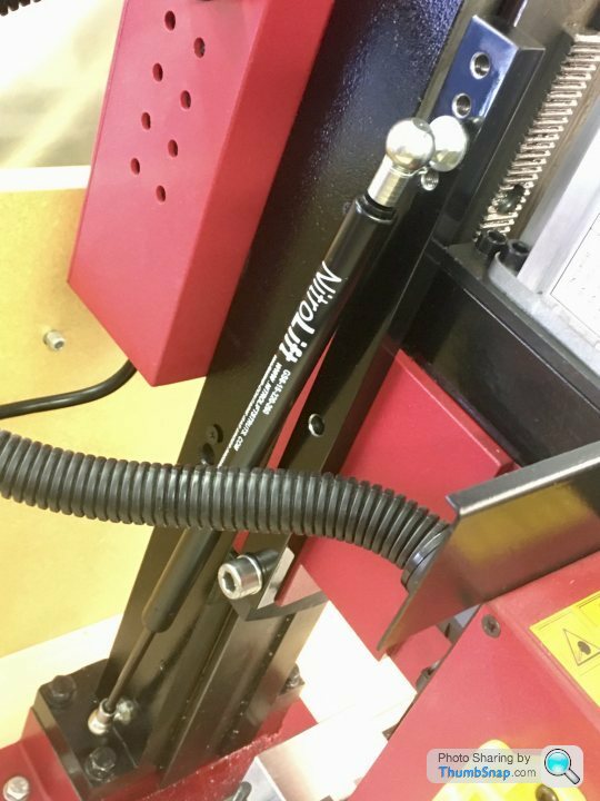 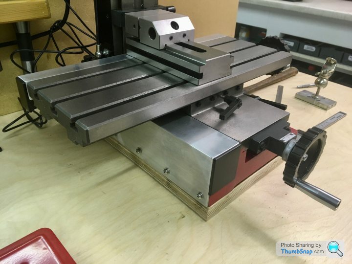 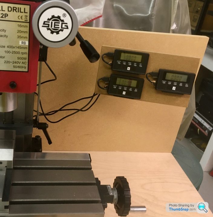 Anyway, I’ve just machined some test pieces on the mill, and this is where the questions start… 1) I couldn’t adjust the gibs properly with the slides assembled, so I removed the leadscrews, locked one axis and adjusted the other. I tested with a DTI by rocking the appropriate slide. I got about 0.001” of play and couldn’t get it any better. I found that an Allen key was useless for this task – too springy, so I used an Allen bit. I also found that the difference between movement and locked was significantly less than 1/8 turn of the grub screws. Question: I know I should aim for zero movement, but what is acceptable in reality? 2) I trammed the bed by mounting a DTI with its holder post in a collet, zeroing on a point on the bed, and turning it to the other 90 degree points over the width of the bed, and over the the equivalent length side-to-side. The diameter of the circle where the quadrant points were checked is around 130mm. The collet chuck was about 250mm above the bed. By shimming with steel, after a long, long time, I got each point to be within 0.001” of the zero datum point. I noticed that the needle moves beyond this limit if I pull on the column (not surprising I guess), but this will probably be representitive of cutting loads. Question: I know I should aim for zero on all points, but what is acceptable in reality? 3) I started by milling some vice clamps out of steel. I found the DROs worked great in conjunction with a Starrett edge finder. Overall, for a first attempt I was very happy with the dimensions achieved. However, I noticed a series of lines in the milled surfaces of the block, which could be felt running a finger over the surface. These aren’t machining swirls. Polishing with a buffing wheel improved matters, but this is obviously not the answer from an engineering viewpoint. I assumed it was poor tramming, so I re-trammed (to get to the aforementioned 0.001” figure), and milled (conventional) a test piece. This was exactly the same. I then dressed the edges with a file, turned the block upside down, and repeated the process. Same again. I then measured the thickness of the block in 9 places. I was getting about 0.002” thickness difference. The block is about 60mm x 40mm x 16mm thick. I was taking about 0.5mm deep cuts with a 10mm diameter 2 flute slot drill (it’s all I have at the moment, but I’ve got some 4 flute end mills on order). I was using cutting oil on the surface as a lubricant. Speed was about 1500 – 2000 rpm. Feed rate “steady”. There was some noise and minor vibration. I also tried milling a piece of aluminium, and the effect is there but much less obvious. Question: What can I do to get rid of ridging and dimensional error? 4) General questions: For my Stuart 10V, if I leave my mill as it is now with it’s current issues (if they are issues with this type of machine), will I be able to make my 10V to a good standard? In other words, it’s fine to want a perfect machine tool, but more relevant to me at present is “what accuracy do I need – am I chasing someting that’s not achievable with a Chinese machine tool”? I’ve included some images below (I hope they will show up). Thanks very much in advance! 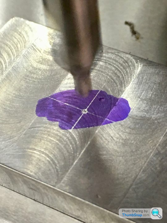   Reply to Topic |
| Andrew Johnston | 07/05/2020 16:35:54 |
 7061 forum posts 719 photos | A few notes: I normally aim for a thou or less when tramming my mill, over a diameter of 200mm or so. No idea what happens if I lean on the table after adjusting the gibs; never felt the need to measure it. My manual mill is pretty worn so adjusting the gibs is a compromise anyway. I just do it by judging a slight 'drag' when moving the table. The manual mill is a knee mill and the column is large by hobby standards. The CNC mill has a conventional column but I've never leant on it to test. I just make parts. The machining marks are indicative of a blunt or pooly ground cutter. Where did the cutter come from? Is the cutter HSS or carbide? Your speeds are a bit fast for HSS but slow for carbide. If there was vibration and noise something is wrong. As before a worn of poor quality cutter, or the most common early error is feeding to slowly. Rule 1: the cutter needs to cut not rub. Rule 2: cutters are consumsable items, don't try and make it last for ever by pussyfooting about on feedrates. I wouldn't bother with cutting oil, especially if it isn't flood coolant. If it is applied in dribs and drabs it just makes a s sticky mess which is sure to cause re-cutting of the swarf, damaging the cutter and making a mess of the finish. Machining a block to an accurate thickness on a mill is seemingly simple, but is much more difficult than it looks. Even if the mill is perfect the results are highly reliant on how the work is clamped and the quality of the machine vice, if used. If I get better than 2 thou on a 6" square I'm happy, and that's on a large mill with a industrial quality machine vice. Andrew PS: If I've an edge finder and DRO available I wouldn't bother marking out and centre popping. Just zero the DRO on a convenient corner, move to hole position and drill - quick 'n' easy. Edited By Andrew Johnston on 07/05/2020 16:37:55 |
| John Haine | 07/05/2020 16:46:58 |
| 5563 forum posts 322 photos | Which gib were you adjusting? At one stage I bought an SX1 for CNC conversion, same table as the SX2P I think, and the gibs were appalling. At least for the Y slide, I machined a new gib from 1/8 brass strip and it was much better, I disposed of the X1 when I bought a Novamill. I think the X slide gib might have been a bit better, but the Y one was made of metal that was too thin and bent. Jason is the expert here, but I agree that the cutter is worn to get that effect. When I started I was very careful about using slow speeds and feeds, but cutters work much better when you apply some welly. I agree with Jason on this - just make some parts. Someone I know made a 10V where he "machined" the bedplate on a sheet of emery on a piece of glass. Edited By John Haine on 07/05/2020 16:48:21 |
| Dr_GMJN | 07/05/2020 16:51:56 |
1602 forum posts | Thanks very much Andrew. I fully appreciate that making parts is more relevant than messing about chasing an impossible setup. However, my lack of experience means that I want to at least start with a setup that's in the right ballpark. I'm trying to determine where I am with that by initially making small parts for the mill, like the gas-strut mount, and the vice clamps, and doing some simple test pieces. Believe me I want to start on some real work asap. The cutter was an HSS slot drill. When you say machining marks caused by a defective tool - do you mean the swirls, or the ridges, or both? It wasn't rubbing - definitely cutting. Any advice on rpm for this diameter and depth of cut? I did indeed end up with a sticky mess of oily swarf which I'm still cleaning up... I marked out the centre of the work because I have to admit I've never really done it before, and wanted to check that a) my marking out method was accurate, and b) that I could use the edge finder and DROs properly. I hope that I haven't made two random errors that happened to coincide in one point!
|
| Dr_GMJN | 07/05/2020 16:56:13 |
1602 forum posts | Posted by John Haine on 07/05/2020 16:46:58:
Which gib were you adjusting? At one stage I bought an SX1 for CNC conversion, same table as the SX2P I think, and the gibs were appalling. At least for the Y slide, I machined a new gib from 1/8 brass strip and it was much better, I disposed of the X1 when I bought a Novamill. I think the X slide gib might have been a bit better, but the Y one was made of metal that was too thin and bent. Jason is the expert here, but I agree that the cutter is worn to get that effect. When I started I was very careful about using slow speeds and feeds, but cutters work much better when you apply some welly. I agree with Jason on this - just make some parts. Someone I know made a 10V where he "machined" the bedplate on a sheet of emery on a piece of glass. Edited By John Haine on 07/05/2020 16:48:21 John, It applied mostly to the x & y gibs. The z-axis is so heavy and has an overhanging load so I just did the best I could by feel rather than with a DTI. TBH I'm more concerned with the potential tramming issue, but first I'll make another of the four clamps with a different cutter and see what that's like. BTW who is Jason? Thanks. |
| Andrew Johnston | 07/05/2020 17:13:02 |
7061 forum posts 719 photos | A rule of thumb for HSS cutters in low carbon steel is 100ft/min cutting speed. For a 10mm cutter that's about 970rpm. Slightly slower is better than slightly too fast. A depth of cut of 0.5mm is small, but should be no problem. How do you know it was cutting? I'd be feeding at 100mm/min or more. If you know the pitch of the leadscrew you can work out how many times a minute you need to turn the handle. The swirls can be produced by several issues. First as the tips wear, or if they're badly ground in the first place, they will cut inconsistently. Second, dragging swarf around with the cutter scores the work as the swarf gets trapped under the cutting edge. Third, the material matters. A 'sticky' steel like EN3 or hot rolled steel is much more prone to this problem than EN1A. The ridges between cuts imply that the cutter isn't cutting cleanly. Assuming the mill is trammed, you shouldn't be able to feel any ridge. Do you know what spec the steel is? Fair enough on the marking out. Ahem years ago I was taught marking out and centre popping but now I only use it for sheet metalwork, where I'm cutting/drilling by hand. But of course one needs confidence before flying with no safely harness. Andrew |
| JasonB | 07/05/2020 17:13:13 |
 25215 forum posts 3105 photos 1 articles | I wish I had had a dti when I made my 10V, steel rule, firm leg calliper, 100mm square I made myself and an ancient rusty micrometer were all I had Expect I have similar movement in my table if I were to push and pull it but I like to run with a fairly loose X axis anyway Tram is within reasonable expectations, I have a bit more lean the the X3 than the SX2.7 but it's has not stopped me. 2-flute cutter not ideal for facing, try less overlap, about 2/3rds cutter width and a finish pass of half that depth. As soon as a cutter looses its edge or does not come with a sharp edge if really cheap then it starts to ride up on the surface and can give both the swirls and steps Without knowing what the bottom of the block was on hard to comment on thickness, tool being pushed off the surface it won't be cutting where it should. Machine as setup should be capable, the rest is down to you. Edited By JasonB on 07/05/2020 17:15:07 |
| Andrew Johnston | 07/05/2020 17:16:45 |
7061 forum posts 719 photos | Posted by John Haine on 07/05/2020 16:46:58:
Jason is the expert here.............. Amazing, being quoted and he hasn't even posted in this thread. That's definitely action at a distance. Search for member JasonB. Andrew Bother, shouldn't have taken the time to proof read. Edited By Andrew Johnston on 07/05/2020 17:17:25 |
| Dr_GMJN | 07/05/2020 17:34:33 |
1602 forum posts | Posted by JasonB on 07/05/2020 17:13:13:
I wish I had had a dti when I made my 10V, steel rule, firm leg calliper, 100mm square I made myself and an ancient rusty micrometer were all I had Expect I have similar movement in my table if I were to push and pull it but I like to run with a fairly loose X axis anyway Tram is within reasonable expectations, I have a bit more lean the the X3 than the SX2.7 but it's has not stopped me. 2-flute cutter not ideal for facing, try less overlap, about 2/3rds cutter width and a finish pass of half that depth. As soon as a cutter looses its edge or does not come with a sharp edge if really cheap then it starts to ride up on the surface and can give both the swirls and steps Without knowing what the bottom of the block was on hard to comment on thickness, tool being pushed off the surface it won't be cutting where it should. Machine as setup should be capable, the rest is down to you. Edited By JasonB on 07/05/2020 17:15:07
Thanks very much Jason. That's all good by me. As I said, all I'm after is confirmation Im in the right setup ballpark. I'd rather make parts than adjustments. BTW the block was resting on ground parallels in the milling vice. I'll try again tonight with the next vice clamp and use the same cutter with a finishing pass - I want to make progress. When I get the new cutters I can make a comparison.
Edited By JasonB on 07/05/2020 17:39:43 |
| JasonB | 07/05/2020 17:39:08 |
25215 forum posts 3105 photos 1 articles | If it's blunt then the finishing pass won't be worth doing, even more likely to just ride over the surface. |
| JasonB | 07/05/2020 17:47:49 |
25215 forum posts 3105 photos 1 articles | Here is a good example, slot on the left cut with a blunt cutter, one on the right with the same cutter after shapening.
|
| Martin Connelly | 07/05/2020 17:54:02 |
 2549 forum posts 235 photos | I would suggest getting a fly cutter as part of your tool collection. A number of people (including me) use insert tooling in them with good results. This has been covered in other threads in the past. With a fly cutter smaller items can be faced in one pass and often the trailing edge does not reach the workpiece so less chance of the sort of finish you have got. Martin C Link added Edited By Martin Connelly on 07/05/2020 17:56:40 |
| Dr_GMJN | 07/05/2020 18:15:21 |
1602 forum posts | Posted by Andrew Johnston on 07/05/2020 17:13:02:
A rule of thumb for HSS cutters in low carbon steel is 100ft/min cutting speed. For a 10mm cutter that's about 970rpm. Slightly slower is better than slightly too fast. A depth of cut of 0.5mm is small, but should be no problem. How do you know it was cutting? I'd be feeding at 100mm/min or more. If you know the pitch of the leadscrew you can work out how many times a minute you need to turn the handle. The swirls can be produced by several issues. First as the tips wear, or if they're badly ground in the first place, they will cut inconsistently. Second, dragging swarf around with the cutter scores the work as the swarf gets trapped under the cutting edge. Third, the material matters. A 'sticky' steel like EN3 or hot rolled steel is much more prone to this problem than EN1A. The ridges between cuts imply that the cutter isn't cutting cleanly. Assuming the mill is trammed, you shouldn't be able to feel any ridge. Do you know what spec the steel is? Fair enough on the marking out. Ahem years ago I was taught marking out and centre popping but now I only use it for sheet metalwork, where I'm cutting/drilling by hand. But of course one needs confidence before flying with no safely harness. Andrew It was generating chips, so I assume it was cutting OK. I can't remember the grade of steel. I bought some blocks about 15 years ago to practice on, I asked for stuff that was easy to machine. It so happens I can get 2 clamps out of each block once theyre sawn in half. I'll try a lower speed. Thanks. |
| Dr_GMJN | 07/05/2020 18:19:11 |
1602 forum posts | Posted by Martin Connelly on 07/05/2020 17:54:02:
I would suggest getting a fly cutter as part of your tool collection. A number of people (including me) use insert tooling in them with good results. This has been covered in other threads in the past. With a fly cutter smaller items can be faced in one pass and often the trailing edge does not reach the workpiece so less chance of the sort of finish you have got. Martin C Link added Edited By Martin Connelly on 07/05/2020 17:56:40
Martin, Thanks for that - noted. If I'm cutting cast iron, intermittently, is a carbide tip going to be OK? |
| Dr_GMJN | 07/05/2020 18:26:26 |
1602 forum posts | Just looked at fly cutters on Arc Euro. If I got an R8 version, do I need a special 8mm insert tool, or can I use a standard lathe tool? Thanks. |
| JasonB | 07/05/2020 18:31:56 |
25215 forum posts 3105 photos 1 articles | Left hand lathe tool if you want to run insert tooling or the HSS-Co5 tool ARC do cuts well enough, I usually just go with HSS
|
| Martin Connelly | 07/05/2020 19:02:08 |
2549 forum posts 235 photos | I've never broken an insert with intermittent cuts on the lathe or using a fly cutter on the mill but do take it easy on depth of cut until it is continuous cutting. As Jason says use hss and you may find it is fine and its cheaper than inserts if the cutting edge needs to be sharper. The use of insert cutter or hss may depend on lots of factors and what is best may depend on material and machine as much as anything else. Cast iron cuts nicely but can be supplied with a hard surface scale that can take the edge off hss very quickly. This has been covered in other threads that are worth looking for. You need to get under it to remove it. Martin C |
| JasonB | 07/05/2020 19:05:48 |
25215 forum posts 3105 photos 1 articles | Inserts should be fine if you want to go that way. plenty of face mills using them and the insert does not know if it is on its own or several in a head. |
| Dr_GMJN | 07/05/2020 19:16:52 |
1602 forum posts | Thanks guys. A long time ago I did some fairly simple 'work' work on the ML7, and was given a set of Sandvik tool holders and inserts. I've got a left hand holder, so I might go for an R8 holder and see how I get on. BTW genuine Sandvik inserts seem to be eye-wateringly expensive, so I ordered some cheaper ones that should fit. Re. continuous cuts - I doubt there will be any on the 10V. I want to start on the base and bearing plate, which as you know are just hollow outlines really. Is it worth removing the casting skin on a linisher first? |
| JasonB | 07/05/2020 19:20:16 |
25215 forum posts 3105 photos 1 articles | Not of you are going at it with carbide and going buy the recent comments you may not have much to come off anyway. |

Please login to post a reply.
Magazine Locator
Want the latest issue of Model Engineer or Model Engineers' Workshop? Use our magazine locator links to find your nearest stockist!
Sign up to our Newsletter
Sign up to our newsletter and get a free digital issue.
You can unsubscribe at anytime. View our privacy policy at www.mortons.co.uk/privacy
Latest Forum Posts
- *Oct 2023: FORUM MIGRATION TIMELINE*
05/10/2023 07:57:11 - Making ER11 collet chuck
05/10/2023 07:56:24 - What did you do today? 2023
05/10/2023 07:25:01 - Orrery
05/10/2023 06:00:41 - Wera hand-tools
05/10/2023 05:47:07 - New member
05/10/2023 04:40:11 - Problems with external pot on at1 vfd
05/10/2023 00:06:32 - Drain plug
04/10/2023 23:36:17 - digi phase converter for 10 machines.....
04/10/2023 23:13:48 - Winter Storage Of Locomotives
04/10/2023 21:02:11 - More Latest Posts...
- View All Topics
Support Our Partners


Shopping Partners
Subscription Offer

Latest "For Sale" Ads
- Reeves** - Rebuilt Royal Scot by Martin Evans
by John Broughton
£300.00 - BRITANNIA 5" GAUGE James Perrier
by Jon Seabright 1
£2,500.00 - Drill Grinder - for restoration
by Nigel Graham 2
£0.00 - WARCO WM18 MILLING MACHINE
by Alex Chudley
£1,200.00 - MYFORD SUPER 7 LATHE
by Alex Chudley
£2,000.00 - More "For Sale" Ads...
Latest "Wanted" Ads
- D1-3 backplate
by Michael Horley
Price Not Specified - fixed steady for a Colchester bantam mark1 800
by George Jervis
Price Not Specified - lbsc pansy
by JACK SIDEBOTHAM
Price Not Specified - Pratt Burnerd multifit chuck key.
by Tim Riome
Price Not Specified - BANDSAW BLADE WELDER
by HUGH
Price Not Specified - More "Wanted" Ads...
Get In Touch!
Do you want to contact the Model Engineer and Model Engineers' Workshop team?
You can contact us by phone, mail or email about the magazines including becoming a contributor, submitting reader's letters or making queries about articles. You can also get in touch about this website, advertising or other general issues.
Click THIS LINK for full contact details.
For subscription issues please see THIS LINK.
Digital Back Issues


Donate

 Register
 Log-in
Model Engineer Magazine
- Percival Marshall
- M.E. History
- LittleLEC
- M.E. Clock

ME Workshop
- An Adcock
- & Shipley
- Horizontal
- Mill

Subscribe Now
- Great savings
- Delivered to your door

Pre-order your copy!
- Delivered to your doorstep!
- Free UK delivery!
All Forum Topics > Beginners questions > Setting up a Mini Mill & Stuart 10V Machining