Forum sponsored by:

Sieg SX3 and Machine-DRO 3-Axis Kit
| Mike Donnerstag | 09/04/2020 21:43:38 |
 231 forum posts 53 photos | I have a Sieg SX3 milling machine and have just purchased a 3-axis DRO kit from Machine-DRO. Does anyone have experience of fitting this kit to the SX3? I have laid out all the parts of the kit on my workbench and more I'm a little befuzzled (technical term). I noticed a page on the internet where someone had mounted the Z-axis scale on the inside of the column, though I couldn't find any detailed photos. Has anyone else done this? The readout came with just a solid horizontal mounting bar and two relatively big (I think M8) bolts. I'm not sure what to mount this to, as the SX3 column 'cover' is just fabricated from relatively thin sheet steel. How have people mounted the DRO display to the machine? Please help! I don't want to drill and tap holes in the wrong place!! Many thanks, Mike
|
| Steviegtr | 09/04/2020 21:54:23 |
 2668 forum posts 352 photos | Have you had a look on youtube. Lots of dro conversions on there. If not your model at least get some idea's. Steve. |
| Steviegtr | 09/04/2020 23:32:52 |
2668 forum posts 352 photos | Try this one. It is a Grizzly G0704 but similar points of fixing. Steve. |
| Martin Mcgiff | 10/04/2020 05:40:48 |
| 5 forum posts 19 photos | I've just fitted one last week as im now onto the cross slide. You need to move the black controller back section out 30mm to allow for the scale to fit inside, also if you clip off 10mm each side of the black controller then the head can lift 60mm higher (bonus )
I will sort some pictures later today
Martin |
| Ron Laden | 10/04/2020 06:26:44 |
 2320 forum posts 452 photos | Google fitting DRO to sx3 and you will find quite a lot of info. |
| JasonB | 10/04/2020 07:04:44 |
 25215 forum posts 3105 photos 1 articles | On my fairly similar X3 I fixed the bottom bracket to the base of the column, make sure you raise the end of the scale enough so the Y one can pass under it. These are M-DRO scales and covers.
Then at the other end fixed down into the top of the column using one of the existing cover screws
Will take a photo of how the read head is fixed to the mill's head later but yours may need a slightly different fixing due to the swivel head. Have you got alink for the SX3 kit as I can't see one listed on their site.
Edited By JasonB on 10/04/2020 07:49:08 |
| Mike Donnerstag | 10/04/2020 08:17:00 |
231 forum posts 53 photos | Thanks chaps. I think I'll fit the X and Y axes first, as they are more straightforward. I have several more questions, which I should probably call Machine-DRO about, though I'd like to get the DRO fitted over the Easter weekend, hence why I'm asking here. I also intend to do more research on the internet to see if I can find answers to these questions, though if anyone knows, it could save me a lot of time and I would be very grateful. Q: On each magnetic scale is printed "INC 2mm -->" Any idea what this means? Q: Has anyone fitted the Z axis INSIDE the column? It seems like an elegant way to conceal the scale, though I'm not sure whether there would be any dificulties. Q: The M-DRO 'Encoder Install Guide' says nothing about actually cutting the scales to length, apart from how to measure. Any tips here? Q: The package came with many powder-coated brackets that aren't in the photograph on the website. Are these additional brackets for the Z axis? Q: How have people attached the display to the machine. I notice on the Axminster version that the arm is fitted to a long rod or bolt, not included in the kit. Again, if anyone has photos I would be very grateful. Once again, many thanks, Mike |
| Mike Donnerstag | 10/04/2020 10:44:13 |
231 forum posts 53 photos | JasonB: Many thanks for your photos. The kit I was recommended by Machine-DRO to buy is a universal mounting kit with magnetic scales. I went for the 3 axis kit with the LCD DRO: https://www.machine-dro.co.uk/easson-lcd-3-axis-dro-package-5955 Thanks, Mike |
| Mike Donnerstag | 13/04/2020 15:18:48 |
231 forum posts 53 photos | The 'Universal Fitting Kit' is proving to be universally frustrating! Has anyone used the fitting kit or has everyone made up their own brackets for fitting the DRO scales and head? If anyone has actually used the fitting kit, would you be able to post some photos? Edited By Mike Donnerstag on 13/04/2020 15:19:33 |
| Martin Mcgiff | 13/04/2020 15:39:53 |
| 5 forum posts 19 photos |
I made my own as was a better instalation as i also fitted the z axis in the column and moved the controller box back 30mm Edited By Martin Mcgiff on 13/04/2020 15:40:23 |
| Mike Donnerstag | 13/04/2020 15:45:38 |
231 forum posts 53 photos | Hi Martin - many thanks for the photos. By 'controller box' do you mean the display? Do you have any other photos? Are these the optical encoders? |
| Martin Mcgiff | 13/04/2020 15:55:24 |
| 5 forum posts 19 photos | The machine controller i mean is the big black box on the back of the machine, i moved it by 30mm to allow the scale to be fitted inside, i also modified it to allow the head to travel 50mm higher, i fitted the DRO arm to the top of the controller box on the right hand side, it is ok and at the right height to read it. i have painted the floor today but will get some pictures tomorrow
Regards
Martin
|
| Mike Donnerstag | 13/04/2020 16:01:56 |
231 forum posts 53 photos | That's great - many thanks. It sounds as if you've done some interesting modifications. Looking forward to the photos. Cheers, Mike |
| Ron Laden | 13/04/2020 16:14:40 |
2320 forum posts 452 photos | Hi Mike, I cant speak for the SX3 but I fitted my Sieg SX2P mill with a 3 axis set (from ARC) and they came with a variety of brackets and fixings, some of which I modified and used but also made some of my own. I think that is the norm when you get a universal kit, probably different when you have a set made for a specific make and model of machine. Unless you can find someone or a write up that covers the detail and parts used in fitting a DRO set to the SX3 you may find that you are on your own. Actually its not that difficult to fit a set just takes a bit of sizing up, positioning and either using the supplied fittings or modifying them and/or making your own. Ron Edited By Ron Laden on 13/04/2020 16:18:20 P.S. There you go Martin will probably have all the info you need. Edited By Ron Laden on 13/04/2020 16:19:40 Edited By Ron Laden on 13/04/2020 16:20:12 |
| Mike Donnerstag | 13/04/2020 17:59:42 |
231 forum posts 53 photos | Hi Ron, Thanks for that information. I think I'm coming to the same conclusion - the 'fit-everything' kit actually fits nothing well, and needs extensive modification to achieve a usable result, albeit ugly. For a much neater result, it seems that making all of the brackets from scratch is the only way, and probably the way I'll go for each axis. Mike |
| Martin Mcgiff | 14/04/2020 12:11:07 |
| 5 forum posts 19 photos | Just on second coat of the garage floor but some quick pictures this morning of position ot the DRO arm, inside the rear column 2 cross beams and a bracket (all inside the black control panel) i moved back the screws on top 30mm to allow for this and i also removed 10mm each side at the top to allow the head to rise 50mm higher !!!
|
| Mike Donnerstag | 14/04/2020 16:13:58 |
231 forum posts 53 photos | Interesting! Many thanks Martin. |
| Martin Mcgiff | 15/04/2020 16:31:58 |
| 5 forum posts 19 photos | I have Moved the milling machine back into its final position, picture showing the DRO arm position |
| Mike Donnerstag | 27/04/2020 12:58:29 |
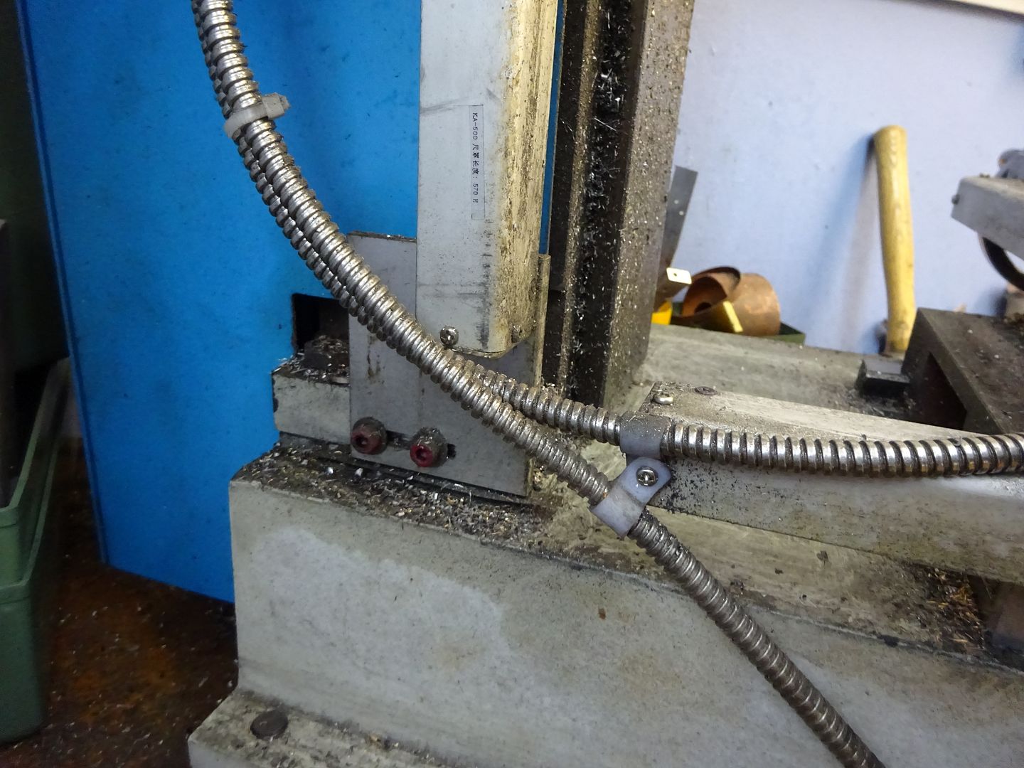
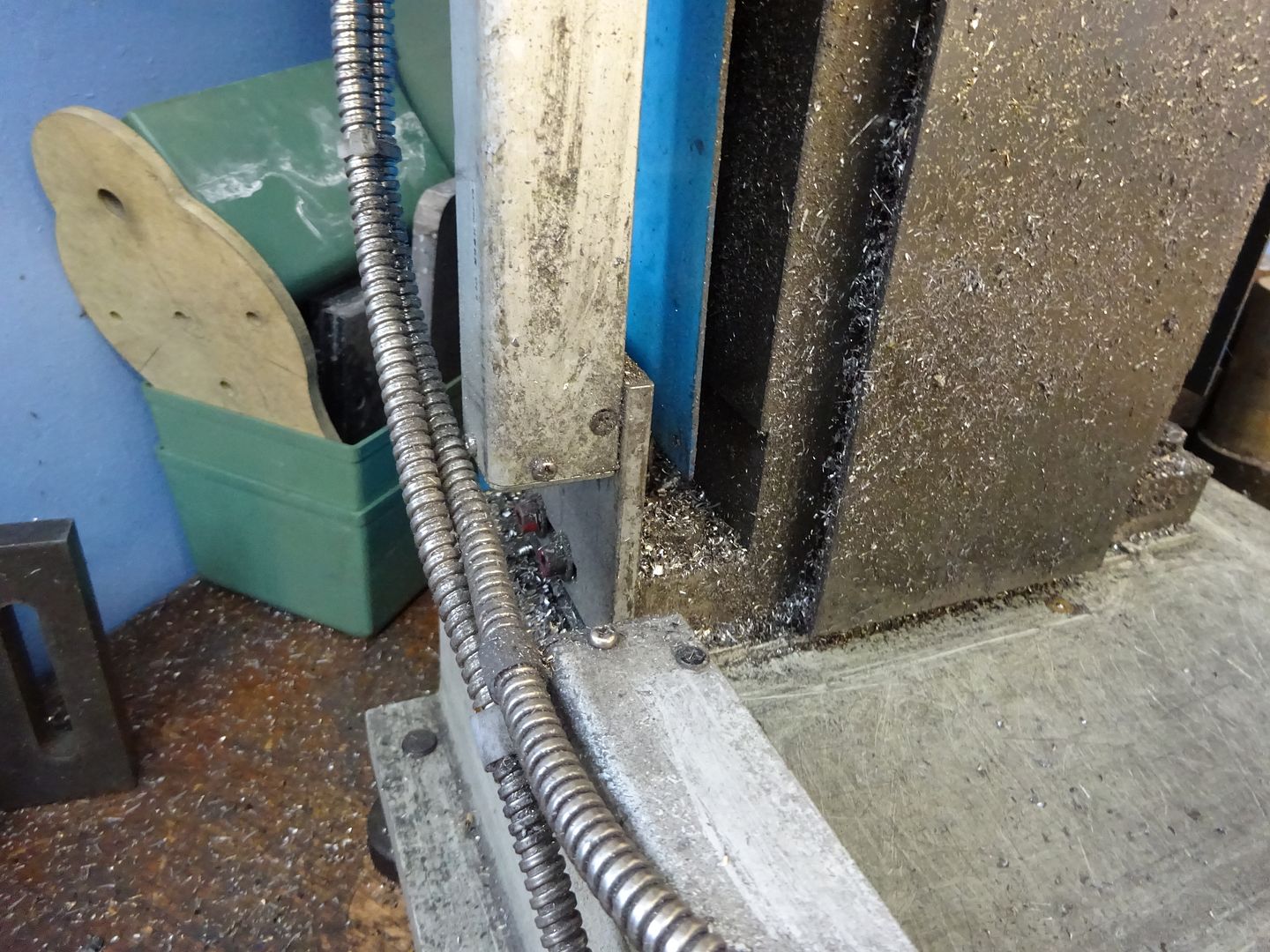
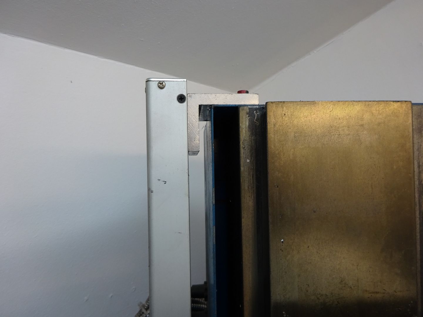
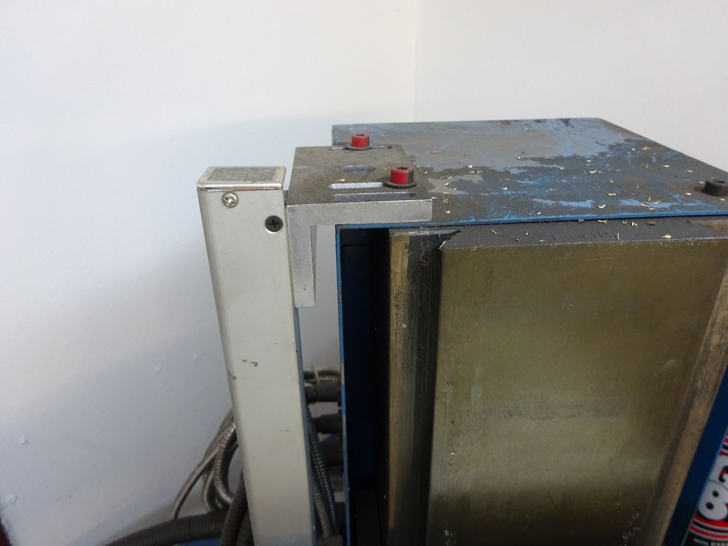
231 forum posts 53 photos | Many thanks to everyone who commented on this post. I decided to install the Z-axis inside the column, as far back as possible to ensure the cable does not foul the Z-axis leadscrew. Photos follow:
I'd be very interested if anyone has any comments. Mike |
| James Hall 3 | 09/05/2021 23:47:20 |
| 92 forum posts 12 photos | I'm impressed by the neatness of your installation, particularly with the mounting in the rear column. I've just invested in a 3-axis kit for my SX3 from MachineDRO so would like to pick your brains and benefit from your experience if you don't mind. It will be a while before I actually find time for my installation but I'd like to get it clear in my mind how I will go about it. It may be that I should address some questions to MDRO, and that the answers to some will or would be obvious when the rear column cover is removed - but in a restricted space my mill takes a lot of moving so a quick look inside beforehand is not so easy. An easy starter - you obviously discovered how to cut the magnetic strips to length, please tell. Is the mounting for the display fixed to the pressed-steel cover, or through it to something more substantial? On the X-axis you have mounted the scale on the table with the read head fixed, but vice-versa for the Y-axis - with the scale fixed and the head travelling with the saddle. Why have you chosen to do thi? I'll leave the rest, rather than over-burden you with the whole lot in one installment. Thanks. |

.jpg")


Please login to post a reply.
Magazine Locator
Want the latest issue of Model Engineer or Model Engineers' Workshop? Use our magazine locator links to find your nearest stockist!
Sign up to our Newsletter
Sign up to our newsletter and get a free digital issue.
You can unsubscribe at anytime. View our privacy policy at www.mortons.co.uk/privacy
Latest Forum Posts
- *Oct 2023: FORUM MIGRATION TIMELINE*
05/10/2023 07:57:11 - Making ER11 collet chuck
05/10/2023 07:56:24 - What did you do today? 2023
05/10/2023 07:25:01 - Orrery
05/10/2023 06:00:41 - Wera hand-tools
05/10/2023 05:47:07 - New member
05/10/2023 04:40:11 - Problems with external pot on at1 vfd
05/10/2023 00:06:32 - Drain plug
04/10/2023 23:36:17 - digi phase converter for 10 machines.....
04/10/2023 23:13:48 - Winter Storage Of Locomotives
04/10/2023 21:02:11 - More Latest Posts...
- View All Topics
Support Our Partners


Shopping Partners
Subscription Offer

Latest "For Sale" Ads
- Reeves** - Rebuilt Royal Scot by Martin Evans
by John Broughton
£300.00 - BRITANNIA 5" GAUGE James Perrier
by Jon Seabright 1
£2,500.00 - Drill Grinder - for restoration
by Nigel Graham 2
£0.00 - WARCO WM18 MILLING MACHINE
by Alex Chudley
£1,200.00 - MYFORD SUPER 7 LATHE
by Alex Chudley
£2,000.00 - More "For Sale" Ads...
Latest "Wanted" Ads
- D1-3 backplate
by Michael Horley
Price Not Specified - fixed steady for a Colchester bantam mark1 800
by George Jervis
Price Not Specified - lbsc pansy
by JACK SIDEBOTHAM
Price Not Specified - Pratt Burnerd multifit chuck key.
by Tim Riome
Price Not Specified - BANDSAW BLADE WELDER
by HUGH
Price Not Specified - More "Wanted" Ads...
Get In Touch!
Do you want to contact the Model Engineer and Model Engineers' Workshop team?
You can contact us by phone, mail or email about the magazines including becoming a contributor, submitting reader's letters or making queries about articles. You can also get in touch about this website, advertising or other general issues.
Click THIS LINK for full contact details.
For subscription issues please see THIS LINK.
Digital Back Issues


Donate

 Register
 Log-in
Model Engineer Magazine
- Percival Marshall
- M.E. History
- LittleLEC
- M.E. Clock

ME Workshop
- An Adcock
- & Shipley
- Horizontal
- Mill

Subscribe Now
- Great savings
- Delivered to your door

Pre-order your copy!
- Delivered to your doorstep!
- Free UK delivery!
All Forum Topics > Workshop Tools and Tooling > Sieg SX3 and Machine-DRO 3-Axis Kit