Forum sponsored by:

Kity W oodwork Machine Switch Again
| Clive B 1 | 28/01/2020 13:54:47 | ||
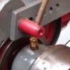
| 110 forum posts 76 photos | Hi Guys I’ve just got around to having another look at changing the switch on the Kity Machine. I’ve stripped the switch down a little further but I’m still not sure what the wires connect to inside the motor case or how they should connect to a DOL starter with overload protection. I’ve lettered the wires so if all else fails at least I can connect them back onto the existing switch and continue to use it as original. There are six wires going into the motor casing, namely the Yellow (A) Red (B) Brown (C) Blue (D) Brown (E) Black (F) As shown on my sketch. Does anyone have any ideas on how the wires should be connected to a DOL starter working off the pictures and the wiring sketch? Thanks to anyone who can help
| ||
| Ian Parkin | 28/01/2020 14:53:22 | ||
 1174 forum posts 303 photos | Clive is the original switch simply on/off or is it 3 position forward/off/reverse? | ||
| Clive B 1 | 28/01/2020 15:58:58 | ||
| 110 forum posts 76 photos | Hello again Ian Thank you for your reply, its simply an on/off switch, there is no reverse. | ||
| Ian Parkin | 28/01/2020 17:44:45 | ||
1174 forum posts 303 photos | Clive are you happy to try things ? I realise that some dont like high voltage messing about. But if you can try this and report back remove the switch completely connect the earth from the plug to the motor connect the live (brown) to red(b) and the brown going to the capacitor (dont lift by this) connect the neutral (blue) to blue (d) black (f) and brown (c) connect the blue from the capacitor to yellow (a) insulate the brown (e) not sure what this does as yet
then try plugging in the motor should run
report back if it does or doesnt Ian | ||
| Brian Morehen | 28/01/2020 19:07:39 | ||
 191 forum posts 11 photos | Machine w ireing is not important. just connect your blue and brown to your DOL syarter switch then and a further length of 3 core flex to the other side contccts in your DOL starte relay .connevt the where availabe the ont o your machine this will complte the earthing process . any overload protection should be then complete if provided with your new started switch .Eveething thenshould be OK.
Regards Brian Morehen | ||
| Clive B 1 | 28/01/2020 19:10:36 | ||
| 110 forum posts 76 photos | Hi Ian I’ll give it a try, although it may be Thursday before I can do it as I’m out most of tomorrow. So, I assume I will be completely bypassing the switch which normally lives on top of the motor? Also is there any chance this test will burn anything out in the motor or will it just trip an mcb. or the rcd on the fuse board if it doesn’t like the connection setup? | ||
| Ian Parkin | 28/01/2020 19:20:54 | ||
1174 forum posts 303 photos | Brian the original switch (a unistop ) is a strange one (isnt everything french) and as standard it has a NVR function built in which is why Clive wants to change it so he can start and stop the motor and spinning blades remotely Theres internal wiring in it to the a and b terminals and where the yellow loop wire is Clive it will blow the fuse or trip mcb/rcd if theres a major fault but just plug it in for a few seconds to see if it starts first Edited By Ian Parkin on 28/01/2020 19:22:28 | ||
| Emgee | 28/01/2020 19:33:11 | ||
| 2610 forum posts 312 photos | Brian Another opinion to consider. If you re-connect all wiring to as it was before you disconnected anything you only then have to wire the mains supply to the original supply terminals on the switch. Leave the existing switch in the ON position when using the DOL starter, but leaving it in circuit provides a means of isolating the motor when changing cutting heads or blades. Emgee | ||
| Ian Parkin | 28/01/2020 20:23:37 | ||
1174 forum posts 303 photos | Emgee its a NVR switch | ||
| Emgee | 28/01/2020 22:01:13 | ||
| 2610 forum posts 312 photos | Posted by Ian Parkin on 28/01/2020 20:23:37:
Emgee its a NVR switch I missed that important point, thought there was a works schematic for the motor/switch but doesn't seem to be available now. Emgee | ||
| Brian Morehen | 29/01/2020 08:45:10 | ||
191 forum posts 11 photos | Any Control fitted into you mains lead will not have any .effect on any control s beyond this point Brian | ||
| Clive B 1 | 30/01/2020 15:13:41 | ||
| 110 forum posts 76 photos | Hi Ian I made the connections as you said taping them together so hoped the connections were good enough, then very very briefly started the motor. It ran in the correct direction but after switching it off and trying it a second time all I could hear was a buzzing noise so I switched it off before any tell-tale smoke appeared. | ||
| Clive B 1 | 30/01/2020 15:43:13 | ||
| 110 forum posts 76 photos | Ian False alarm ignore my last comment, I tried it again and the motor started up, spinning in the correct direction. I guess I was a bit jittery and was switching off more or less before it had time to start up, anyway I ran it for 30 seconds, switched off and tried again and it started up. I don’t know what the brown wire (e) is for so I guess it’s back over to you, incidentally I haven't purchased a new switch yet. I’m thinking maybe have just one but have it on a lead so it can be moved around the machine table to whatever one I’m working on. I await your next instruction
Clive | ||
| Brian Morehen | 31/01/2020 08:33:20 | ||
191 forum posts 11 photos | When switched of does your machine stop quickly or slow down slowly. Puzzle 6 wires going into the motor 2 May be Start windings Centrifugal changes this to Run windings . Further 2 May reverse the motor rotation when switched of to act as brake to stop motor. If we knew the Ohms readings on these Possible 3 sets of windings if theyare the case lots of questions and answers may start to make some sence. Yes a Scematic wireing diagram would provide all of the answers , at the moment we are all trying to find the correct answer. Brian
| ||
| Ian Parkin | 31/01/2020 09:12:00 | ||
1174 forum posts 303 photos | Clive so all good so far when you unplug the motor and its coasting to a stop do you hear a click from the motor? This is the centrifugal switch which wires in the capacitor in or out of circuit ( if fitted) On the other hand it may be a permanently capacitor run motor I'm not sure what the spare brown wire is but it will hold the coil in the start switch in i think Have you access to a meter to measure ac current? we now need to measure how much its dawing whilst running
Ian | ||
| Ian Parkin | 31/01/2020 09:14:24 | ||
1174 forum posts 303 photos | Clive make sure that you have permanently mounted stop switches mounted if you do have a switch in a lead you do need to reach stop quickly in a panic | ||
| Clive B 1 | 31/01/2020 14:34:44 | ||
| 110 forum posts 76 photos | Ian No, I don’t hear a click from the capacitor now but when the old switch was connected to the motor yes there was a click after switch off. I do have a multimeter but have to admit I’ve only used it for doing bits of continuity checks on the car. I’ve included a picture of it to give you an idea of what it’s like. If I do have to do tests on the wires is there any better way of joining them together because at the moment, I haven’t cut the spade connectors off and they are only held together with electrical tape so not exactly the tightest of connections. I left the spades on just in case I end up having refit the old switch. Switches, I understand what you say about stop switches, I haven’t bought anything yet as I wanted to try and get the wiring sorted out first and then get advice of you guys on what would be best to go for as I don't want to end up buying the wrong things. I have had a reply from Axminster Tools as follows: Used primarily for motor switching. Three different ratings to suit single phase motor powers from 750W - 3.75kW Units for 750W, 2.25kW or 3.75kW motors. Adjustable overload protection: 340192 - 6A to 8A 340193 - 14A to 17A 340194 - 17A to 21A Can be used with additional foot switches, interlocking micro switches or thermal overloads. 175mm (6⁷⁄₈ʺ IP54 rated against dust and moisture ingress. You can add glands and stops if you want, but if modified it in any way and does not work we cannot arrange a return/refund.
Kind regards Ian the above is info is about the switch I spoke of in my previous posting. I have still had to contact Axminster again because on their web site they have conflicting info ie. 2.25kW reads as 1,500W on their drop down price list. Thanks again Clive
| Clive B 1 | 31/01/2020 15:08:17 |
| 110 forum posts 76 photos | Brian I thank you for your valued input, I would say the motor slows down slowly when switched off, taking as near as dam it 13 seconds to come to a standstill I timed it, that’s of course with no drive belts attached to the pulleys to put any drag on it.
If I’d got a schematic diagram you guys would be the first to know about it, given how old the motor is I don’t think there’s much chance of getting one. Having said that even when it was in its heyday manufacturers tend not to give that sort of information out, well not if they can help it. Thanks again Clive | ||
| Ian Parkin | 31/01/2020 17:24:11 | ||
1174 forum posts 303 photos | I think you will need a clamp type meter to read the current as its likely to be drawing perhaps 30 amps on start up for 1/2 a second I was at a place of work yesterday and the owner was complaining that his saw bench was blowing fuses when cold on checking my meter was showing readings of 50-60 amps for an instant before settling to 11 amps so not surprising it was blowing 13 amp fuses.. so i wired it to a 16amp plug and put a socket direct to fuse board with a 20 amp mcb anyway back to your problem clive The click i was wanting you to listen for was from the motor itself not the capacitor.. the click you heard with the original switch was probably the coil in the switch dropping out. If you cant lay your hands on a ac ammeter i dont really know what to suggest. you dont want to burn out any windings in your motor as its a very expensive motor that..
where are you Clive? Geographically? | ||
| Brian Morehen | 31/01/2020 18:08:44 | ||
191 forum posts 11 photos | Yes you do require a clip on ammeter, Your meter would have to be connected in series to obtain a reading and probably will not go high enough in the Amperage range How high does it go needs to be 10 amps AC or higher I have a clip on meter .Depends where you live Not any where In Cambridgeshire? Yes you may here the centrifugal Switch click out . Capacitor start is a Question . Some Motors do not have capacitors . I have Four that do not Capacitors. Brian |


 high x 100mm (4ʺ
Please login to post a reply.
Magazine Locator
Want the latest issue of Model Engineer or Model Engineers' Workshop? Use our magazine locator links to find your nearest stockist!
Sign up to our Newsletter
Sign up to our newsletter and get a free digital issue.
You can unsubscribe at anytime. View our privacy policy at www.mortons.co.uk/privacy
Latest Forum Posts
- *Oct 2023: FORUM MIGRATION TIMELINE*
05/10/2023 07:57:11 - Making ER11 collet chuck
05/10/2023 07:56:24 - What did you do today? 2023
05/10/2023 07:25:01 - Orrery
05/10/2023 06:00:41 - Wera hand-tools
05/10/2023 05:47:07 - New member
05/10/2023 04:40:11 - Problems with external pot on at1 vfd
05/10/2023 00:06:32 - Drain plug
04/10/2023 23:36:17 - digi phase converter for 10 machines.....
04/10/2023 23:13:48 - Winter Storage Of Locomotives
04/10/2023 21:02:11 - More Latest Posts...
- View All Topics
Support Our Partners


Shopping Partners
Subscription Offer

Latest "For Sale" Ads
- Reeves** - Rebuilt Royal Scot by Martin Evans
by John Broughton
£300.00 - BRITANNIA 5" GAUGE James Perrier
by Jon Seabright 1
£2,500.00 - Drill Grinder - for restoration
by Nigel Graham 2
£0.00 - WARCO WM18 MILLING MACHINE
by Alex Chudley
£1,200.00 - MYFORD SUPER 7 LATHE
by Alex Chudley
£2,000.00 - More "For Sale" Ads...
Latest "Wanted" Ads
- D1-3 backplate
by Michael Horley
Price Not Specified - fixed steady for a Colchester bantam mark1 800
by George Jervis
Price Not Specified - lbsc pansy
by JACK SIDEBOTHAM
Price Not Specified - Pratt Burnerd multifit chuck key.
by Tim Riome
Price Not Specified - BANDSAW BLADE WELDER
by HUGH
Price Not Specified - More "Wanted" Ads...
Get In Touch!
Do you want to contact the Model Engineer and Model Engineers' Workshop team?
You can contact us by phone, mail or email about the magazines including becoming a contributor, submitting reader's letters or making queries about articles. You can also get in touch about this website, advertising or other general issues.
Click THIS LINK for full contact details.
For subscription issues please see THIS LINK.
Digital Back Issues


Donate

 Register
 Log-in
Model Engineer Magazine
- Percival Marshall
- M.E. History
- LittleLEC
- M.E. Clock

ME Workshop
- An Adcock
- & Shipley
- Horizontal
- Mill

Subscribe Now
- Great savings
- Delivered to your door

Pre-order your copy!
- Delivered to your doorstep!
- Free UK delivery!
All Forum Topics > Website Questions, Comments, and Suggestions > Kity W oodwork Machine Switch Again