Forum sponsored by:

ML1 Worn Saddle adjustment
| Chris V | 08/12/2019 15:03:46 |
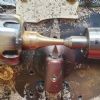 313 forum posts 42 photos | Hi all, yesterday was a bit of a milestone as some of the wheels on my ML1 turned under power for the first time since Ive had it (11 months of faffing!) But I see there is an issue with the saddle, or is it the carriage? to be clear the part that the cross slide will be mounted on and that slides left to right on the dovetailed bed ways. Ive roughly adjusted the 3 rear jib strip screws on the far side so its not loose, ie dosent twist at both ends of the bed. But it does in the centre where its no doubt been mostly used and I'm assuming its worn. I tightened 2 grub screws a little on the clasp nut which may or may not have helped. So question is how to proceed please? Cheers Chris. |
| Brian Wood | 09/12/2019 09:41:28 |
| 2742 forum posts 39 photos | Hello Chris, I am unclear about what you refer to as the clasp nut and the grub screws associated with it; if they are what I think they might be that will not help at all in correcting the slew you are getting part way down the length of the bed. Sadly I believe you are correct in diagnosing bed wear and the short answer for an old lathe of that vintage is to learn to live with it and develop coping strategies. I think it very unlikely you will find any organisation who would be prepared to regrind the bed and angled side edges, nor would you be happy with the cost if you do find one. Depending on your experience and expertise some might suggest you try remedial scraping of the side edges either side of centre to level out the playing field so to speak, but it is by no means an easy skill to master even on flat surfaces and then to put into practice on shapes like that. For a first job I would avoid it. An approach I might take if the lathe was mine is to try careful lapping with fine grinding paste of the side edges with a wedge shaped wooden block, fastened to a section of flat plywood riding on the top of the bed and "working out" the high areas to either side of centre. I know it sounds dreadful to contemplate such practice but with due care and a good straight rule to refer to, the limits of the hollowing can be spread out to form an average over the length of the bed. I do emphasize that CARE is the watchword and cleaning up very thoroughly every trace of residual abrasive material is essential to prevent further unintended wear later on. I hope that helps you with some ideas, but such problems are to be expected on old lathes that have really done their time. Regards Brian
|
| Chris V | 09/12/2019 10:59:38 |
313 forum posts 42 photos | Thanks so much Brian, yes that's some good food for thought. First off I will check it with a straight edge to confirm its that, then try to develop coping strategies and then you have given me two options to consider. Cheers Chris. |
| blowlamp | 09/12/2019 12:11:51 |
 1885 forum posts 111 photos | That does sound like bed wear to me. Regrinding the bed could be problematic, but you might be able to find someone with a decent sized vertical mill that would be prepared to give a lick to the worn surfaces and get you back with a usable machine again. It's what I would do.
Martin. |
| Lainchy | 09/12/2019 13:00:52 |
 273 forum posts 103 photos | I've no idea how much it would cost, but I'd be interested just out of noseyness Best of luck. Ian |
| Bazyle | 09/12/2019 13:44:54 |
 6956 forum posts 229 photos | If the saddle is slewing you probably realise that as well as the bed each end of the saddle gets extra wear. Thus when you snug it up tight the middle is making contact but each end is probably clear. So with a short contact length it is even easier for it to twist. |
| Chris V | 09/12/2019 14:07:18 |
313 forum posts 42 photos | Thanks Ian, I just spoke to the chap at slideways but he's retired. He did say though that if he was still working maybe £300, and the people in charge of Myford would charge around double that. As my lathe cost around £250 its as we though a non starter, but interesting to know all the same. Thank you too Bazyle. As a complete novice no I had not thought of that. The ML1 gib strips are only 1/8"or so thick, I guess this would be easy enough to replace if overly worn, if so I can see that should at least help matters. Out of curiosity what sort of size are the Drummond gib strips? I will go and check now, I should be working but that far too overrated! (-: Cheers Chris. |
| Chris V | 09/12/2019 15:32:50 |
313 forum posts 42 photos | Ok chaps Ive just taken another look, yes there's some wear to the bed, as to be expected, though perhaps not too bad, time will tell when I try cutting some metal. But me thinks the greater issue is the backlash of the saddle when its engaged with the rack and clasp nut. As I understand things I either manually move the saddle via the handle on the lead screw at tailstock end of the lathe, or via the wheel/handle on the saddle, or the saddle moves under power via change wheels-lead screw-clasp nut -saddle. When the saddle lever is engaged I can move the saddle by hand towards and away from the headstock, which is what I understand as backlash. When it comes to cutting metal this is going to cause issues no doubt. Question is, is there a way of adjusting/reducing this? There are two grub/set? screws in the vacinity of the clasp nut but tightening these does not seem to help. Maybe even though the engagement lever is fully down there might be a way of adjusting it so it locks things up tighter? I am of course assuming when this lever is fully depressed there should not be this lateral movement in the saddle.... Any suggestions most gratefully received! Cheers Chris. |
| Brian Wood | 09/12/2019 16:20:59 |
| 2742 forum posts 39 photos | Ah, now Chris you are getting into different matters from bed wear. The clasp nuts that grip the leadscrew from either side could well be partly choked with swarf, scraped off the leadscrew as it ran though them. That will prevent full engagement. I don't know if the ML1 had an adjustable stop screw to limit the degree of engagement of the clasp nuts, but if one is fitted it will be screwed into the lower of the clasp nuts to provide a positive stop to prevent over tight grip on the leadscrew which only wears both components. Swarf in the clasp nuts is easily removed by taking off the apron on the front of the saddle [open the clasp nuts fully to clear the leadscrew] and then it can be picked out with a cocktail stick or something like it. You will also be able to observe that the clasp nuts slide in a vertical slideway with each moved by a screw fitting into a curved slot on either side of centre of the actuating handle.. The rack and pinion are at fixed positions with respect to each other. I imagine the gear teeth are worn as well on the pinion but I seem to remember that was an interference fit on the shaft and it might be possible to knock the shaft out, turn the gear round and then squeeze them together again in between vice jaws. If that is not possible on your model, you can re-position the rack downward by slotting the screw holes and setting it lower. It will take out much of the lost motion on manual traversing of the saddle along the bed. You will also find that as you wind that gear handle, the saddle moves in the opposite direction to what you might expect. That is a cheap motion of gear into rack, without an idler between them to correct things so that motion is logical. You will get used to it but be careful if using another machine you are unfamiliar with! Regards Brian |
| Howard Lewis | 09/12/2019 18:51:08 |
| 7227 forum posts 21 photos | Comments. The Myford M Series have dovetail beds, so wear on the dovetails may be less easy to recover, than on the flat top of the bed. So your check with a straight edge needs to include the dovetails, (The rear dovetail may be even more difficult! ) as well as the flat top of the bed. There will be backlash between the pinion and the rack. This is the normal method of moving the saddle, manually. Which is what you would do most of the time. In any case it is quicker than winding along with the Leadscrew, which will need 8 turns to advance the Saddle by an inch The half nuts will be engaged with the Leadscrew if you wish to set up the change gears to provide a power feed for turning, to cut screwthreads, or to advance the Saddle by a measured distance. For what my advice is worth, I would check one thing at a time, staring with the rear dovetail; then the front dovetail, and then the flat top of the bed, correcting the wear in each feature. But remember that you will have difficulty putting on metal, if you remove too much. So proceed VERY carefully. My first purchases would be a tin of Micrometer blue, and a good 12 " straight edge, plus laying in a good stock of clean rag, and Swarfega, with which to clean my. hands. SLOWLY SLOWLY CATCHEE MONKEE! When you happy with the bed, then clamp an accurate bar in the chuck, (1/2" minimum dia Silver Steel possibly ) and check that the Headstock is aligned with the bed. Unless your lathe is a very early one with a cast in Headstock, it should be possible to correct any misalignment by slackeinng the 1/4 BSF nuts that hold the Headstock to the bed. Once that has been done, fit centres, and with a properly centre drilled bar and starting checking the Tailstock for alignment in first the horizontal plane, and then in the vertical plane. Adjusting for Zero deflection horizontally should be fairly easy, using the 1/4 BSW adjuster on the far side of the Tailstock. Recheck after locking with the nut! If the centres are out vertically, you may have to scrape the underside of the Tailstock to bring the centres into alignment. If the tailstock centre is low, you will need to find some means of adding shims. Again,BE CAREFUL, not to make matters worse! You do want a Tailstock barrel that points towards the sky, or the floor. Either way, you will need to check that when the vertical alignment is correct, that the horizontal has not been changed since first set up. Once you have got the lathe into alignment with as little backlash as possible, you should have a useable, mand useful, machine, even if it has foibles compared to a modern machine. Howard |
| Chris V | 09/12/2019 19:00:11 |
313 forum posts 42 photos | Thanks so much Brian this is most helpful. Probably as you were writing your message I decided to take the saddle apart to investigate. I didn't notice an adjustable stop screw though I will check for it tomorrow. I did notice however that rod that is screwed into the bottom half of the clasp nut that locates in the curved slot in the engagement wheel is at its limit, the top one has room left to travel to close down on the lead screw. I did wonder about filing a little out of the end of the curved slot to allow more travel but there's not much metal between the end of the slot and the wheels centre shaft. I'm not sure if that would help though. I did clean out some crud and adjusted the gibs on the half nuts. The gear wheel for the rack looks ok but I will bear turning that around as an option. The rack I replaced in the summer from one off an ML4 as the original had broken teeth. Unfortunately even though I made a neat job of filling the old screw fixing holes as they did not align with my casting I never considered I might need to lower it due to wear! Oh well, I can see that slotting the holes is going to help matters so I will certainly do that. Oh and my neighbour noticed for me some of the lateral movement is in fact the lead screw moving side to side, no doubt a washer will help that! Cheers Chris. |
| Chris V | 09/12/2019 19:35:26 |
313 forum posts 42 photos | Thank you Howard, most helpful. Funnily enough I only thought to check the dovetails, I forgot the top! Comes from being a cabinet maker perhaps! But yes I will check that too now you mention it. You say there will be backlash between the pinion and the rack, do you mean that's inevitable on a lathe of this age, or that there should be/would have to be from new? I recall the most helpful Tony from Lathes.co.uk said to me the rack and pinion should not be a tight fit,.. in any case as I replaced the rack and looking at the fit between it and the gear it seems sensible to slot the rack holes and drop it a little closer, especially if its going to help sort the rather excessive backlash. I'm sure from the name Micrometer blue is going to be different from marking out blue which I have, but would this work ok? Good news is I have ORANGE Swarfega (-: so much nicer!! I won't try scraping anything just yet for fear of making matters worse, but its good to know there are possible home remedies for such issues! Oh yes mines an early one, cast in headstock, pics in my photo album. I don't think I have an adjuster at the rear of my tailstock, I think the only way to adjust that laterally is with the front gib strip. Tailstock is shown in my Album too. If anyone has the same tailstock I'd love to see a pic of the original clamping lever, mine came with a simple nut, I will have to use a spanner on it till I can make a replacement. Ok I know NOTHING about metal scraping? Cheers Chris.
|
| Bazyle | 09/12/2019 21:27:41 |
6956 forum posts 229 photos | Backlash in the leadscrew doesn't matter and there isn't any means provided for correcting it. It comes from two places as you have noticed, the fit of the nut on the thread and the movement of the screw itself. This becomes more relevant when you look at backlash on the cross and top slides. Backlash of the rack and pinion matter even less. I suggest you clean everything and have a play with some bits of plastic and aluminium so you get used to the controls. Also do lots of reading about lathes so you get to know the terms and can understand the advice more easily. |
| Chris V | 09/12/2019 23:15:29 |
313 forum posts 42 photos | Thanks Bazyle seems like there's hope for the old girl yet then! Yes the bed on my ML1 is dovetailed front and back. Cheers Chris. |
| Hopper | 10/12/2019 06:47:59 |
 7881 forum posts 397 photos | ^^^^^ What Bazyle said. And if you are learning to use an ML1 you definitely need one of these: LINK |
| Lee Rogers | 10/12/2019 07:33:52 |
 203 forum posts | My approach to these type of issues with the Drummonds that I have restored is firstly to go at it gently and get the best compromise that you can. Something you can live with is the goal ,not perfection. Once your happy with it some minor mods to allow all motions to be locked.( This may be a feature already on the ML) Locking whatever your not moving for a particular task will solve all manner of problems. New Drummond users regularly have issues with chatter , poor finish etc and the answer is usually failure to lock the carriage , cross or topslide. One other thing will improve your turning and that is to use HSS tooling. Buy a small set to get going and then learn to grind your own. You could also come and join us on the Drummond Myford FB group.. |
| Brian Wood | 10/12/2019 09:36:29 |
| 2742 forum posts 39 photos | Chris, While I do not wish to contradict the advice given by Howard for setting up the tailstock, I remember only too well from the ownership of my father's ML4 after he died the tedious alignment difficulties caused purely by the quite dreadful limitations of locating the front gib strip. You can get two centres aligned tip to tip but getting the tailstock aim down the bed is an entirely different matter. A far quicker and I am sure a more accurate method is to wind out the barrel and grip that in a 3 jaw chuck. Now you have it held in line with the headstock you can move the tailstock gib about accordingly and clamp it to the tailstock to hold the setting. There is now a decent chance that any drilling done with the tailstock will be along the bed axis and not at some angle off centre. Regards Brian |
| Chris V | 10/12/2019 10:58:45 |
313 forum posts 42 photos | Thank you Hopper, its on order (-:
Thank you Lee, Whilst i'm a perfectionist at heart and in my work I don't expect the lathe to ever be perfect and of course my engineering skills are still to be gained, but its encouraging to here you say that and will be the approach I take. I was not aware of a Drummond group, oh thats Facebook right? Hmm..still might consider that as I love the look of Drummonds and may have one one day, starting off small though. Oh and I have a small set of new HSS cutters just sitting waiting for me (-: |
| Chris V | 10/12/2019 11:06:04 |
313 forum posts 42 photos | Thank you Brian. That sounds like a really good plan of action! I will indeed try that. Cheers Chris. |
| Howard Lewis | 11/12/2019 13:00:07 |
| 7227 forum posts 21 photos | Chris, Sparey's book is written predominantly with the Myford ML7 in mind, but that is the detail. The principles will apply to any lathe. Others worth considering are Ian Bradley's "The Amateur's Workshop" and Tubal Cain's "Model Engineering Handbook" They are all filled with useful information, especially Tubal Cain's book. As you get further into the hobby, you will find The Workshop Practice series to be very useful. The ML series machines , differ in centre height - 3.125 for the early models ( ML 1 and 2 ) and 3.5 for the later models, with the "higher" numbers denoting a greater centre distance. They all date from just before WW2 and production ceased in the mid 40s The ML7 came out in about 1947. Like all machines of that age, wear and abuse will be apparent, not to mention what we would regard as peculiar foibles, and facilities which we now take for granted, will be absent. Having said that, within the limitations of design, age and abuse, they are still capable of producing good work. Like all machines, careful adjustment can bring about huge improvements in performance. Keep at it! Howard |
 ..... slidewayservices.co.uk of Nuneaton seem to offer regrinding services. A call maybe? What would it be worth to get it done? I'm guessing on a chinese mini lathe.... not so, but a lathe passed down from family generations, with some sentimental value... ?? This is purely hypothetical, and may well not apply to you Chris, but got to be worth a call?
Please login to post a reply.
Magazine Locator
Want the latest issue of Model Engineer or Model Engineers' Workshop? Use our magazine locator links to find your nearest stockist!
Sign up to our Newsletter
Sign up to our newsletter and get a free digital issue.
You can unsubscribe at anytime. View our privacy policy at www.mortons.co.uk/privacy
Latest Forum Posts
- *Oct 2023: FORUM MIGRATION TIMELINE*
05/10/2023 07:57:11 - Making ER11 collet chuck
05/10/2023 07:56:24 - What did you do today? 2023
05/10/2023 07:25:01 - Orrery
05/10/2023 06:00:41 - Wera hand-tools
05/10/2023 05:47:07 - New member
05/10/2023 04:40:11 - Problems with external pot on at1 vfd
05/10/2023 00:06:32 - Drain plug
04/10/2023 23:36:17 - digi phase converter for 10 machines.....
04/10/2023 23:13:48 - Winter Storage Of Locomotives
04/10/2023 21:02:11 - More Latest Posts...
- View All Topics
Support Our Partners


Shopping Partners
Subscription Offer

Latest "For Sale" Ads
- Reeves** - Rebuilt Royal Scot by Martin Evans
by John Broughton
£300.00 - BRITANNIA 5" GAUGE James Perrier
by Jon Seabright 1
£2,500.00 - Drill Grinder - for restoration
by Nigel Graham 2
£0.00 - WARCO WM18 MILLING MACHINE
by Alex Chudley
£1,200.00 - MYFORD SUPER 7 LATHE
by Alex Chudley
£2,000.00 - More "For Sale" Ads...
Latest "Wanted" Ads
- D1-3 backplate
by Michael Horley
Price Not Specified - fixed steady for a Colchester bantam mark1 800
by George Jervis
Price Not Specified - lbsc pansy
by JACK SIDEBOTHAM
Price Not Specified - Pratt Burnerd multifit chuck key.
by Tim Riome
Price Not Specified - BANDSAW BLADE WELDER
by HUGH
Price Not Specified - More "Wanted" Ads...
Get In Touch!
Do you want to contact the Model Engineer and Model Engineers' Workshop team?
You can contact us by phone, mail or email about the magazines including becoming a contributor, submitting reader's letters or making queries about articles. You can also get in touch about this website, advertising or other general issues.
Click THIS LINK for full contact details.
For subscription issues please see THIS LINK.
Digital Back Issues


Donate

 Register
 Log-in
Model Engineer Magazine
- Percival Marshall
- M.E. History
- LittleLEC
- M.E. Clock

ME Workshop
- An Adcock
- & Shipley
- Horizontal
- Mill

Subscribe Now
- Great savings
- Delivered to your door

Pre-order your copy!
- Delivered to your doorstep!
- Free UK delivery!
All Forum Topics > Help and Assistance! (Offered or Wanted) > ML1 Worn Saddle adjustment