Forum sponsored by:

Spindle design
| Steve Crow | 23/10/2018 19:12:55 |
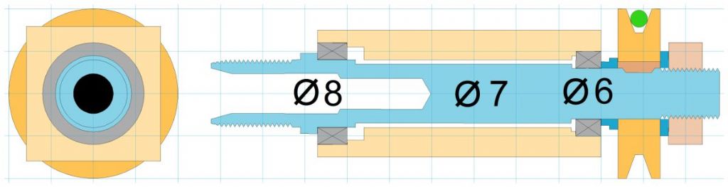
| 429 forum posts 268 photos | I've decided to have a go at a micro spindle to take proxxon collets up to 1/8". I've attached a scale drawing of what I have in mind. Please be aware that the finished housing will be 100mm long. It's just shorter on the drawing for convenience. The grid lines are 5mm and the colours have no bearing on the actual material.
Can anybody see a reason this will not work? Please feel free to comment or ask further questions. Many thanks Steve
|
| Chris Gunn | 23/10/2018 19:22:32 |
| 459 forum posts 28 photos | I would suggest you would need some end float on the rear bearing, make the business end captive, with a cover plate, and the rear bearing needs a bit of clearance so it can float and not bind up on assembly or when running. you may have allowed for this, but it is not obvious from the section. Chris Gunn |
| Steve Crow | 23/10/2018 20:06:51 |
| 429 forum posts 268 photos | Thanks Chris, I intended to loctite in the front bearing. By clearance and float on the rear bearing do you mean axial or radial? Cheers Steve |
| Emgee | 23/10/2018 20:14:40 |
| 2610 forum posts 312 photos | Hi Steve The weak link looks like the small size of the belt drive, perhaps a flat or multi vee belt would give better performance. Emgee |
| Joseph Noci 1 | 23/10/2018 22:01:16 |
| 1323 forum posts 1431 photos | Steve, I don't believe 'actual' end float is needed - Rather design the shaft/pulley/end nut so that you can apply a small pre-load, and lock the end nut in place with maybe another nut - lock-nut style. And try to make the spindle shaft and the spindle housing of the same material so that thermal expansion coefficients are close to the same - that way the bearing will be treated more kindly. Also, nothing wrong with your pulley/belt style - I used that on tool post grinders - internal/external, spinning up to 14,000RPM, with a brushless drive motor of up to 800watts..The belt is a sort of neoprene - 6mm diameter, from RS-Components, and you cut to length and heat-join the cut ends. Works very well, and is cheap to replace - mine has lasted around 120 grinding hours... The spindle takes ER11 collets, but has a hole through for a draw bar that pulls tight extensions to which are fitted grinding wheels, as in these photos. The extension I make up as need for any special wheel - inner grinding or outer with bigger ( 50mm diameter) wheels, etc. The extension where the draw bar pulls is a male ER11 collet fit. You may be able to fit a 3mm or 4mm draw bar to your design as well? The brushless motor on this unit is 500watts max - 60mm diameter, 70mm long, running of 36volts DC
|
| Emgee | 23/10/2018 22:13:07 |
| 2610 forum posts 312 photos | Joseph, check the belt size as shown, 5mm grid makes the belt diameter about 2mm, not 6mm as you used. Emgee |
| Chris Gunn | 23/10/2018 22:36:56 |
| 459 forum posts 28 photos | I meant axial. Chris
|
| Pete Rimmer | 23/10/2018 23:24:44 |
| 1486 forum posts 105 photos | Posted by Joseph Noci 1 on 23/10/2018 22:01:16:
Steve, I don't believe 'actual' end float is needed - Rather design the shaft/pulley/end nut so that you can apply a small pre-load, and lock the end nut in place with maybe another nut - lock-nut style. And try to make the spindle shaft and the spindle housing of the same material so that thermal expansion coefficients are close to the same - that way the bearing will be treated more kindly. Also, nothing wrong with your pulley/belt style - I used that on tool post grinders - internal/external, spinning up to 14,000RPM, with a brushless drive motor of up to 800watts..The belt is a sort of neoprene - 6mm diameter, from RS-Components, and you cut to length and heat-join the cut ends. Works very well, and is cheap to replace - mine has lasted around 120 grinding hours... The spindle takes ER11 collets, but has a hole through for a draw bar that pulls tight extensions to which are fitted grinding wheels, as in these photos. The extension I make up as need for any special wheel - inner grinding or outer with bigger ( 50mm diameter) wheels, etc. The extension where the draw bar pulls is a male ER11 collet fit. You may be able to fit a 3mm or 4mm draw bar to your design as well? The brushless motor on this unit is 500watts max - 60mm diameter, 70mm long, running of 36volts DC
Man that's a nice job you made of that. |
| Joseph Noci 1 | 24/10/2018 07:40:10 |
| 1323 forum posts 1431 photos | Hi Emgee, Yes, I realised that, but Steve's spindle would not be absorbing a hundred watts or so as mine does on occasion - a 2mm belt will do just fine for his application - I am sure he can even go up to 3mm. RS does the belting down to 3/32 of an inch and that will do just fine. Joe |
| Joseph Noci 1 | 24/10/2018 07:50:02 |
| 1323 forum posts 1431 photos | Thank you Pete..was fun making it - I did a second, higher powered one as well, but driven by a toothed belt - that is a mistake which I will retrofit - the vibration from the teeth at high speeds shows through on the grind..
Joe |
| Kiwi Bloke | 24/10/2018 10:22:01 |
| 912 forum posts 3 photos | Steve. Your proposed spindle's diameter is pretty small for its length. I'd guess that you want to be able to run the spindle up to, say, 20,000 RPM. I'd be inclined to make the spindle as large a diameter as you think you can. That would give you the possibility of a central bore, although you probably don't need one for your intended tooling in small collets. However, you never know, and building in versatility is often time well spent. Angular contact bearings would be better than deep-groove bearings. In either case, setting the right pre-load with nuts on the screw-cut spindle might prove to be frustrating. Make it the finest pitch you can. Probably better to apply axial load with a Bellville washer (or a few). Plenty of spindle designs on the 'net and good stuff in Harprit Sandhu's book, No 17 in the Workshop Practice series. I think Chris Gunn's point about an axially non-constrained bearing at the pulley end refers to the more complex, but better, design in which there are loaded, opposed bearings at the spindle nose end. It all depends on how 'good' the thing needs to be... |
| Steve Crow | 25/10/2018 17:17:25 |
| 429 forum posts 268 photos | Just to clarify. The spindle is for use in a tool post and vertical slide on my Sherline lathe. I intend to use it for drilling and very light milling duties for horological type work. I have no intention to use it for grinding. The belt illustrated is 2mm diameter although, as Joseph mentioned I can easily go up to 3mm. I was going to make the thread pitch 0.5mm. Do you think this is fine enough? Also, will I have to use locknuts or is there an alternative? As i am making this on a Sherline, I'm restricted to size. I'm probably going to have to make the housing 80mm long as my centre to centre size will not allow me to drill out any longer. Many thanks Steve |
| duncan webster | 25/10/2018 18:27:59 |
| 5307 forum posts 83 photos | Getting the fit of the rear bearing inner race just right is a small issue with this set up. Too tight and you can't adjust the end float, too sloppy and you could get slip between shaft and race. As the axial load will only be one way, what you can do is put a preload ('wave' ) washer between the rear outer race and the housing, then the inners can be press fitted up to shoulders. The wave washer exerts an axial load at all times and takes up any small radial clearance. This is how Quorn does it, but with a more elaborate preload system. I'd use shielded ball races, not sealed, too much drag,
Edited By duncan webster on 25/10/2018 18:28:35 Edited By duncan webster on 25/10/2018 18:29:18 |
| Steve Crow | 27/10/2018 09:47:24 |
| 429 forum posts 268 photos | Thank you Duncan, I like the idea of a wave washer. I've had a look and the only one available that will fit my assembly just touches both inner and outer races. The drawing below is a section of my bearing and the pink bit is the washer, or rather the space occupied by the uncompressed washer.
I could add a flat washer that only makes contact with the outer race. The pink is the spring and the flat washer is dark blue.
Do you think this could work? Thanks |
| Muzzer | 27/10/2018 11:19:58 |
 2904 forum posts 448 photos | Looks very complicated. Surely it doesn't matter where the wavey washer sits, so you could get rid of the pink and blue between the outer bearing race and housing and instead just fit the wavey washer next to your tightening nut? But unless you define the amount of compression with positive stops, the wavey washer will simply bottom out and you won't have any control of the preload force and might as well not bother with it. Murray |
| duncan webster | 27/10/2018 12:59:04 |
| 5307 forum posts 83 photos | What;'s with the double row bearings? I'd use a 686ZZ (6*13*5) or similar. The blue bit wants to abut the bearing inner, and the outer wants to be a slip fit in its housing |
| Nick Hulme | 27/10/2018 15:51:29 |
| 750 forum posts 37 photos | I made an ER11 spindle a few years ago for engraving and very small milling jobs, it runs at 30000rpm. It was only an afternoon lash-up to get a job done but it's been running fine ever since, it's easy to over complicate things. - Nick |
| Steve Crow | 29/10/2018 17:40:49 |
| 429 forum posts 268 photos | Thanks to everybody who's helped with this.You'll have to bear with me - i'm struggling to get my head round it. Nick, I have the Spindle book but most of the designs use a spacer, something I'm trying to avoid. I really want to make it as simple as possible. Did you make your spindle from an ER11 collet holder with an integral shank? Duncan, it probably isn't a double row bearing. It's low profile(106ZZ 6*10*3) and I just drew them in for illustrative purposes. I'm quite new to this bearing game! I'm still not sure I understand the positioning of the wave washer. Any chance of a rough sketch? Many thanks Steve |
| duncan webster | 29/10/2018 20:15:12 |
| 5307 forum posts 83 photos | sorry it's a bit rubbish, not a lot of time this week. The 6*10*3 is 6mm ID, 10mm OD, 3mm thick, not as you've drawn it. I've also drawn the front bearing wrong but that doesn't matter. The important bit is that you make the housing so that the front bearing takes the axial load as per your original sketch, the rear bearing is trapped hard up axially between the step on the spindle and the pulley/spacer arrangemnent. You arrange the lengths so that when the rear bearing is pulled up tight the wavy washer is preloaded by the right amount. Look in bearing manufacturer's guff about what the right amount is, it is usually more than you'd think. Or give them a ring, they are usually very helpful even if they realise you're only buying one. If the wavy washer overlaps the inner, add another spacer as bottom sketch |
| Kiwi Bloke | 30/10/2018 09:03:29 |
| 912 forum posts 3 photos | As DW above says. Belville (cone) washers may be easier to find than wavy washers and avoid possible interference with the inner race. The washer contacts the outer race by the outer edge of its face only, and 'points' away from the bearing (towards the other bearing). Therefore install two, 'pointing' towards each other (>< * thus: >><<>><< |


.jpg")
 ; the second one's OD contacts the step in the housing bore, as above. As used by Emco in the Unimat headstock - two, with angular-contact bearings in the early Unimat, 4 pairs, back-to-back*, with deep-groove bearings in the Unimat 3. You need a reasonably firm spring to resist the possibility of the spindle moving axially, should it ever be loaded towards the workpiece by, for example, a drill grabbing in brass.
Please login to post a reply.
Magazine Locator
Want the latest issue of Model Engineer or Model Engineers' Workshop? Use our magazine locator links to find your nearest stockist!
Sign up to our Newsletter
Sign up to our newsletter and get a free digital issue.
You can unsubscribe at anytime. View our privacy policy at www.mortons.co.uk/privacy
Latest Forum Posts
- hemingway ball turner
04/07/2025 14:40:26 - *Oct 2023: FORUM MIGRATION TIMELINE*
05/10/2023 07:57:11 - Making ER11 collet chuck
05/10/2023 07:56:24 - What did you do today? 2023
05/10/2023 07:25:01 - Orrery
05/10/2023 06:00:41 - Wera hand-tools
05/10/2023 05:47:07 - New member
05/10/2023 04:40:11 - Problems with external pot on at1 vfd
05/10/2023 00:06:32 - Drain plug
04/10/2023 23:36:17 - digi phase converter for 10 machines.....
04/10/2023 23:13:48 - More Latest Posts...
- View All Topics
Support Our Partners


Shopping Partners
Subscription Offer

Latest "For Sale" Ads
- Reeves** - Rebuilt Royal Scot by Martin Evans
by John Broughton
£300.00 - BRITANNIA 5" GAUGE James Perrier
by Jon Seabright 1
£2,500.00 - Drill Grinder - for restoration
by Nigel Graham 2
£0.00 - WARCO WM18 MILLING MACHINE
by Alex Chudley
£1,200.00 - MYFORD SUPER 7 LATHE
by Alex Chudley
£2,000.00 - More "For Sale" Ads...
Latest "Wanted" Ads
- D1-3 backplate
by Michael Horley
Price Not Specified - fixed steady for a Colchester bantam mark1 800
by George Jervis
Price Not Specified - lbsc pansy
by JACK SIDEBOTHAM
Price Not Specified - Pratt Burnerd multifit chuck key.
by Tim Riome
Price Not Specified - BANDSAW BLADE WELDER
by HUGH
Price Not Specified - More "Wanted" Ads...
Get In Touch!
Do you want to contact the Model Engineer and Model Engineers' Workshop team?
You can contact us by phone, mail or email about the magazines including becoming a contributor, submitting reader's letters or making queries about articles. You can also get in touch about this website, advertising or other general issues.
Click THIS LINK for full contact details.
For subscription issues please see THIS LINK.
Digital Back Issues


Donate

 Register
 Log-in
Model Engineer Magazine
- Percival Marshall
- M.E. History
- LittleLEC
- M.E. Clock

ME Workshop
- An Adcock
- & Shipley
- Horizontal
- Mill

Subscribe Now
- Great savings
- Delivered to your door

Pre-order your copy!
- Delivered to your doorstep!
- Free UK delivery!
All Forum Topics > Workshop Tools and Tooling > Spindle design