Forum sponsored by:

helical lathe prototype - choice of components
| john constable | 11/07/2018 23:45:43 |
 80 forum posts 9 photos | So, after loads of helpful advice I've settled on the following for my project. Its a small tabletop light duty helical turning lathe. Any comments welcome.
https://www.amazon.co.uk/gp/product/B06Y4NYJWN/ref=ox_sc_act_title_3?smid=A16ALI0DJJWDXC&psc=1
https://www.amazon.co.uk/gp/product/B07BB979R4/ref=ox_sc_act_title_4?smid=A281VSOIV3TOD6&psc=1
https://www.amazon.co.uk/gp/product/B071JV158X/ref=ox_sc_act_title_1?smid=A54GFBX2KVQG6&psc=1
 https://www.amazon.co.uk/gp/product/B072J97N8T/ref=ox_sc_act_title_3?smid=AR85BMET0MBNK&psc=1
Edited By john constable on 12/07/2018 00:16:44 |
| SillyOldDuffer | 12/07/2018 22:34:58 |
| 10668 forum posts 2415 photos | Looks like a good way to start John. It already understands G-code (grbl). It also solves the user interface design issues I was wittering about in the other thread because all that is done on a PC. The Arduino gets its instructions off an SD-Card, which keeps that side simple. My only tiny worry would be unwanted side-effects because it's a 3D printer driver. For instance the firmware might make a fuss if the bed & extrusion heating stuff is left disconnected - the motors might wait forever until a non-existent printing part was up to temperature. Shouldn't be a showstopper - I think it's all open source and hackable.
Edited By SillyOldDuffer on 12/07/2018 22:35:40 |
| john constable | 12/07/2018 23:36:42 |
80 forum posts 9 photos | Posted by SillyOldDuffer on 12/07/2018 22:34:58:
Looks like a good way to start John. It already understands G-code (grbl). It also solves the user interface design issues I was wittering about in the other thread because all that is done on a PC. The Arduino gets its instructions off an SD-Card, which keeps that side simple. My only tiny worry would be unwanted side-effects because it's a 3D printer driver. For instance the firmware might make a fuss if the bed & extrusion heating stuff is left disconnected - the motors might wait forever until a non-existent printing part was up to temperature. Shouldn't be a showstopper - I think it's all open source and hackable.
Edited By SillyOldDuffer on 12/07/2018 22:35:40 is that going to be the same with most of these kits? |
| Martin Connelly | 13/07/2018 11:23:51 |
 2549 forum posts 235 photos | It shouldn't be too hard to spoof a few signals to use it as is, my biggest worry would be the torque available from the motors. 3D printing doesn't put much load on a motor so small holding torques don't cause a problem. You may need to up the holding torque by either replacing some of the motors with something beefier or by fitting a planetary gearbox on some of the stepper motors. You will only find out if you need more torque when you have got it all set up and start to cut something. I would work on the basis that as the spindle will not need high rpm for your application there would be no problem putting a 10:1 ratio gearbox on the spindle motor from the off. It may be cheaper than a bigger stepper with its own power supply and driver unit. These motors are 40 N.cm which is the same as 0.4Nm. Since people converting mills and lathes to CNC will be looking at steppers or servos with holding torque up to something like 20Nm you can se where my concern is coming from. Martin C |
| john constable | 13/07/2018 16:40:17 |
80 forum posts 9 photos | Posted by Martin Connelly on 13/07/2018 11:23:51:
It shouldn't be too hard to spoof a few signals to use it as is, my biggest worry would be the torque available from the motors. 3D printing doesn't put much load on a motor so small holding torques don't cause a problem. You may need to up the holding torque by either replacing some of the motors with something beefier or by fitting a planetary gearbox on some of the stepper motors. You will only find out if you need more torque when you have got it all set up and start to cut something. I would work on the basis that as the spindle will not need high rpm for your application there would be no problem putting a 10:1 ratio gearbox on the spindle motor from the off. It may be cheaper than a bigger stepper with its own power supply and driver unit. These motors are 40 N.cm which is the same as 0.4Nm. Since people converting mills and lathes to CNC will be looking at steppers or servos with holding torque up to something like 20Nm you can se where my concern is coming from. Martin C Thanks Martin. My machine is scratch built rather than converting something heavier and the capacity is small i.e. maximum 2" x 10" wooden spindle. Nothing needs to whizz around too fast either as the tool movement will be slow like thread cutting on a lathe rather than a gantry router. So, hopefully nema 17s will be fine.... I'm still trying to understand the whole path of CAD through to driver boards fully.I reckon I can learn to write simple gcode which should be enough for my application and can be put on the SD card but it would be nice to control the tool directly from a window on my pc. Not quite sure how to do that.It would also be useful to emulate the effect of my code on my machine before I commit but I'm not sure how to do that yet either. |
| Martin Connelly | 13/07/2018 17:27:34 |
2549 forum posts 235 photos | Are you thinking along the line of manual data input (MDI) where you tell the machine to move to a certain point (for example) or are you after the ability to just move until you have things where you want them (jog). If the latter then you want to be able to put either a game controller in your system or a manual pulse generator (MPG) as often seen on a pendant. I don't know if something designed for a 3D printer will come with these features. Martin C |
| john constable | 13/07/2018 17:45:31 |
80 forum posts 9 photos | both would be good
|
| SillyOldDuffer | 13/07/2018 18:18:17 |
| 10668 forum posts 2415 photos | Posted by john constable on 12/07/2018 23:36:42:
Posted by SillyOldDuffer on 12/07/2018 22:34:58:
... My only tiny worry would be unwanted side-effects because it's a 3D printer driver. ...
is that going to be the same with most of these kits? I don't know, yours is the first kit I've looked at in any detail. (Most people doing mills and lathes seem to either source the parts individually or buy a commercial solution. ) In terms of controlling your lathe it may not matter:
I'd suggest wiring the motors up on a bench and trying it. If you can make them start, stop and reverse with simple g-code, you're OK. If they don't work it's time to find out why and fix it. Martin may be right about motor torque. I hadn't spotted they're small motors. It's not speed that matters, it's the motor's ability to hold work in position when the tool bites. Embarrassing if applying the tool jams the lathe or pushes a motor in reverse. As Martin says gearboxes will help although they also slow the machine down. Sending individual lines of g-code to the Arduino could probably be easily done with a terminal emulator. I'm not sure controlling a machine directly is a good idea though. Mistakes are punished immediately! If you mistype and tell the lathe to smash the tool into the work, it will. I don't have CNC myself, but believe the approach is to either generate g-code from a computer model or write it by hand. Once the g-code exists it can be tested with a simulator, and/or by stepping though the program line by line on a real machine with no cutters. The purpose is to ensure there aren't any collisions, misses, excessive cuts, or inefficient movements. Once satisfied all is well, cutters are fitted and the program run at full speed. Dave
|
| john constable | 13/07/2018 18:35:21 |
80 forum posts 9 photos | OK - interesting. My strategy to get a kit was that all the components are already selected to work together and as I'm still green that's one less bunch of things to go wrong. However, if I was more confident I would prefer to get them individually. Sounds like one step and emulation are a safer way to go. I'll look for an emulator so I can start to learn g-code while i'm still building the lathe. So, is there a way to send your complete G-code to the arduino from the pc without using the sd card?
|
| JasonB | 13/07/2018 18:53:40 |
 25215 forum posts 3105 photos 1 articles | It would be worth playing with one of the free CAD/CAM packages such as Fusion360 which will generate all the code for you and give an idea of what can be done just from your drawing on a screen before you even go out and buy any parts. This one shows a groove being cut around a cylinder |
| john constable | 13/07/2018 19:24:26 |
80 forum posts 9 photos | It's just too elaborate for what I need. I just need to move the tool about a bit to guide it to cut turned rope twists. I'm just not going to be doing anything sophisticated enough to justify a complex cad image. I'd like to model it in 3d so I can understand the effect of speeds on pitch types and number of spirals on one spindle etc and just get an idea of what it'll look like. |
| SillyOldDuffer | 13/07/2018 20:41:37 |
| 10668 forum posts 2415 photos | Posted by john constable on 13/07/2018 18:35:21:.. ... So, is there a way to send your complete G-code to the arduino from the pc without using the sd card?
Yes, it's easy, perhaps easier than getting the SD Card working. Have a look at this Getting Started page. It also recommends 'that you use one of the many great GUIs that users have written to stream your G-code programs to Grbl and to fully harness all of Grbl's capabilities. NOTE: Check out ShapeOko's Wiki. It has the most up-to-date and comprehensive list of Grbl GUIs.' Following the link reveals loads of options. The way you're approaching this is very sensible. Making use of kits and existing software will save lots of time and brain ache. Dave |
| john constable | 13/07/2018 22:17:15 |
80 forum posts 9 photos | So GRBL is a piece of software - like an OS - that runs on the arduino board and controls the controller board by interpreting gcode that is sent to it by usb from a pc which is running one of many user-written GUIs?
Do the GUIs generate code from instructions you give it or do they convert from a CAD image? |
| SillyOldDuffer | 14/07/2018 10:09:50 |
| 10668 forum posts 2415 photos | Posted by john constable on 13/07/2018 22:17:15:
So GRBL is a piece of software - like an OS - that runs on the arduino board and controls the controller board by interpreting gcode that is sent to it by usb from a pc which is running one of many user-written GUIs?
Do the GUIs generate code from instructions you give it or do they convert from a CAD image? "So GRBL is a piece of software - like an OS - that runs on the arduino board and controls the controller board" - exactly right. It translates G-code commands into the motor steps needed to move a tool or print head to an X,Y,Z coordinate. grbl will respond to commands typed into a character terminal, this is the best way to test your configuration to prove the motors respond correctly to simple commands. For production work that simplicity gets tedious, hence the GUIs. They do the same job but - once properly set up - are slicker, more helpful and whatever else the designer has thought of. What the GUI's do varies a bit, but there look to be three levels of sophistication:
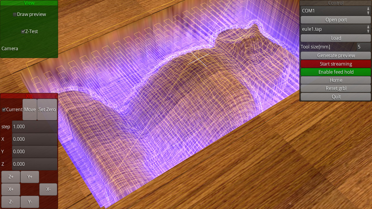
A picture's worth a thousand words, this example is grblgui. (I've not used any of them and can't comment on installation, ease of use, or bugs.)
Do the GUIs generate code from instructions you give it or do they convert from a CAD image? As far as I can see none of the free GUIs convert from CAD, you either type the code in by hand, or load it from a file. The file is usually created by something else; either a conversion program, or by the drawing package itself. Jason's post shows how Fusion360 does it. A superficial read suggests OpenSCAD can't produce g-code directly, rather users export the model as a DXF file and run that through a DXF to G-code converter. At this stage it's worth mentioning a potential booby trap! The g-code files needed to print a 3d object are additive, that is the object is built inside-out by depositing layers until the shape is finished. The g-code instructions needed to mill the same 3d object are subtractive, that is the tool removes material from a solid block until the shape is finished, outside in. grbl doesn't care, but it's possible that software written specifically for 3D printing might not support milling and vice-versa. Your lathe is subtractive and the g-code you send to grbl needs to be that way round. It may be necessary to try a few alternatives to find what suits you best. Dave Dave |
| I.M. OUTAHERE | 14/07/2018 11:20:16 |
| 1468 forum posts 3 photos | Wouldn't it be easier to run a proper cnc controller like mach3 ? It would be seamless with something like fusion 360 cad/ cam which you can get for nothing on startup . You can buy cheap 4 axis engraver / router units that just need to be connected to a pc running mach3 that may do what you want I would build the electronics to be able to handle much more powerful motors - even if you don't need them now you may in the future . Nema 17 motors and the ramps controllers/ drivers are pretty gutless at around 2 amps max . |
| john constable | 14/07/2018 14:26:35 |
80 forum posts 9 photos | Posted by SillyOldDuffer on 14/07/2018 10:09:50:
Posted by john constable on 13/07/2018 22:17:15:
So GRBL is a piece of software - like an OS - that runs on the arduino board and controls the controller board by interpreting gcode that is sent to it by usb from a pc which is running one of many user-written GUIs?
Do the GUIs generate code from instructions you give it or do they convert from a CAD image? "So GRBL is a piece of software - like an OS - that runs on the arduino board and controls the controller board" - exactly right. It translates G-code commands into the motor steps needed to move a tool or print head to an X,Y,Z coordinate. grbl will respond to commands typed into a character terminal, this is the best way to test your configuration to prove the motors respond correctly to simple commands. For production work that simplicity gets tedious, hence the GUIs. They do the same job but - once properly set up - are slicker, more helpful and whatever else the designer has thought of. What the GUI's do varies a bit, but there look to be three levels of sophistication:
A picture's worth a thousand words, this example is grblgui. (I've not used any of them and can't comment on installation, ease of use, or bugs.)
Do the GUIs generate code from instructions you give it or do they convert from a CAD image? As far as I can see none of the free GUIs convert from CAD, you either type the code in by hand, or load it from a file. The file is usually created by something else; either a conversion program, or by the drawing package itself. Jason's post shows how Fusion360 does it. A superficial read suggests OpenSCAD can't produce g-code directly, rather users export the model as a DXF file and run that through a DXF to G-code converter. At this stage it's worth mentioning a potential booby trap! The g-code files needed to print a 3d object are additive, that is the object is built inside-out by depositing layers until the shape is finished. The g-code instructions needed to mill the same 3d object are subtractive, that is the tool removes material from a solid block until the shape is finished, outside in. grbl doesn't care, but it's possible that software written specifically for 3D printing might not support milling and vice-versa. Your lathe is subtractive and the g-code you send to grbl needs to be that way round. It may be necessary to try a few alternatives to find what suits you best. Dave Dave That's all good news - thanks, Dave. So I still need CAM or CADCAM software. I'll persevere with fusion 360. However, as I only really want to turn rather than carve, I can probably do without the CAD stage. I just really wanted to see what my twists would look like and I've been able to do that in OpenSCAD.
That also means the inside-out issue won't affect me so all looking good so far. |
| john constable | 14/07/2018 14:35:38 |
80 forum posts 9 photos | Posted by XD 351 on 14/07/2018 11:20:16:
Wouldn't it be easier to run a proper cnc controller like mach3 ? It would be seamless with something like fusion 360 cad/ cam which you can get for nothing on startup . You can buy cheap 4 axis engraver / router units that just need to be connected to a pc running mach3 that may do what you want I would build the electronics to be able to handle much more powerful motors - even if you don't need them now you may in the future . Nema 17 motors and the ramps controllers/ drivers are pretty gutless at around 2 amps max . Thanks, XD. I won't be engraving or 3D carving as such. I'm just guiding the tool along a slowly rotating spindle of wood so full cnc control software will be overkill unless i have no choice. That's also why I think 17s will be OK but this is just a lightweight prototype to prove the principle and help me understand how it all works. The MkII can use 23s if necessary. |
| Martin Connelly | 14/07/2018 18:41:02 |
2549 forum posts 235 photos | The problem of low torque stepper motors is if they get a small kick when a tool cuts a shaving or bit of swarf they can miss steps. Once out of position they keep on merrily moving things around in the wrong position until there is human intervention or the program stops having produced something that is not quite right. You don't get these types of force with 3D printers, there is no high speed tool spinning around.The other thing is you may be underestimating the amount of force needed to push a work piece and tool together for the cutting action to take place. These motors when used with 3D printers are often driving fine threaded studding which gives some mechanical advantage. Is this what you were thinking of using instead of ball screws? They are not used to push a cutting tool into a work piece either. The Gcode for what you want is trivial don't sweat over it but do get suitable equipment for what you propose otherwise you could be wasting money. Gcode for a barley twist
G01 X0 Y0 Z0 A0 F50 (Move to starting position. Tool over the centre of the work piece at one end and just touching the work piece. Use A=180 for a second start 180° around from the first and add 180 to the A value below ie 360+180=540) G01 Z-1 F25 (Move the tool down 1mm into the work piece) G01 X250 A360 F50 (Move the tool 250mm along the work piece whilst rotating the work piece 360°. Change 250mm and 360° to suit your requirements. G01 Z2 (Lift the tool away from the work piece) G0 X0 A0 (Rapid move back to X=0 G01 Z-2 F25 (Lower the tool 1mm more than before to do a second cut) Repeat with decreasing Z until you have got to the depth you want.
Martin C |
| john constable | 14/07/2018 20:32:39 |
80 forum posts 9 photos | OK, I've listened to all the advice regarding 17s vs 23s. I still think my machine's motors will need very little torque - I can't see a router spindle binding when taking a shallow cut in wood for instance. However I came here for the benefit of your advice so I'd be mad to ignore it. I might also be underestimating the torque needed for my xy table which is quite cheap and, my MKII will probably need 23s and I can move them across. |
| john constable | 14/07/2018 20:33:59 |
80 forum posts 9 photos | Posted by Martin Connelly on 14/07/2018 18:41:02:
The problem of low torque stepper motors is if they get a small kick when a tool cuts a shaving or bit of swarf they can miss steps. Once out of position they keep on merrily moving things around in the wrong position until there is human intervention or the program stops having produced something that is not quite right. You don't get these types of force with 3D printers, there is no high speed tool spinning around.The other thing is you may be underestimating the amount of force needed to push a work piece and tool together for the cutting action to take place. These motors when used with 3D printers are often driving fine threaded studding which gives some mechanical advantage. Is this what you were thinking of using instead of ball screws? They are not used to push a cutting tool into a work piece either. The Gcode for what you want is trivial don't sweat over it but do get suitable equipment for what you propose otherwise you could be wasting money. Gcode for a barley twist
G01 X0 Y0 Z0 A0 F50 (Move to starting position. Tool over the centre of the work piece at one end and just touching the work piece. Use A=180 for a second start 180° around from the first and add 180 to the A value below ie 360+180=540) G01 Z-1 F25 (Move the tool down 1mm into the work piece) G01 X250 A360 F50 (Move the tool 250mm along the work piece whilst rotating the work piece 360°. Change 250mm and 360° to suit your requirements. G01 Z2 (Lift the tool away from the work piece) G0 X0 A0 (Rapid move back to X=0 G01 Z-2 F25 (Lower the tool 1mm more than before to do a second cut) Repeat with decreasing Z until you have got to the depth you want.
Martin C Thanks, for all that Martin. It's been very useful. It's also my first look at real g-code! |


Please login to post a reply.
Magazine Locator
Want the latest issue of Model Engineer or Model Engineers' Workshop? Use our magazine locator links to find your nearest stockist!
Sign up to our Newsletter
Sign up to our newsletter and get a free digital issue.
You can unsubscribe at anytime. View our privacy policy at www.mortons.co.uk/privacy
Latest Forum Posts
- *Oct 2023: FORUM MIGRATION TIMELINE*
05/10/2023 07:57:11 - Making ER11 collet chuck
05/10/2023 07:56:24 - What did you do today? 2023
05/10/2023 07:25:01 - Orrery
05/10/2023 06:00:41 - Wera hand-tools
05/10/2023 05:47:07 - New member
05/10/2023 04:40:11 - Problems with external pot on at1 vfd
05/10/2023 00:06:32 - Drain plug
04/10/2023 23:36:17 - digi phase converter for 10 machines.....
04/10/2023 23:13:48 - Winter Storage Of Locomotives
04/10/2023 21:02:11 - More Latest Posts...
- View All Topics
Support Our Partners


Shopping Partners
Subscription Offer

Latest "For Sale" Ads
- Reeves** - Rebuilt Royal Scot by Martin Evans
by John Broughton
£300.00 - BRITANNIA 5" GAUGE James Perrier
by Jon Seabright 1
£2,500.00 - Drill Grinder - for restoration
by Nigel Graham 2
£0.00 - WARCO WM18 MILLING MACHINE
by Alex Chudley
£1,200.00 - MYFORD SUPER 7 LATHE
by Alex Chudley
£2,000.00 - More "For Sale" Ads...
Latest "Wanted" Ads
- D1-3 backplate
by Michael Horley
Price Not Specified - fixed steady for a Colchester bantam mark1 800
by George Jervis
Price Not Specified - lbsc pansy
by JACK SIDEBOTHAM
Price Not Specified - Pratt Burnerd multifit chuck key.
by Tim Riome
Price Not Specified - BANDSAW BLADE WELDER
by HUGH
Price Not Specified - More "Wanted" Ads...
Get In Touch!
Do you want to contact the Model Engineer and Model Engineers' Workshop team?
You can contact us by phone, mail or email about the magazines including becoming a contributor, submitting reader's letters or making queries about articles. You can also get in touch about this website, advertising or other general issues.
Click THIS LINK for full contact details.
For subscription issues please see THIS LINK.
Digital Back Issues


Donate

 Register
 Log-in
Model Engineer Magazine
- Percival Marshall
- M.E. History
- LittleLEC
- M.E. Clock

ME Workshop
- An Adcock
- & Shipley
- Horizontal
- Mill

Subscribe Now
- Great savings
- Delivered to your door

Pre-order your copy!
- Delivered to your doorstep!
- Free UK delivery!
All Forum Topics > CNC machines, Home builds, Conversions, ELS, automation, software, etc tools > helical lathe prototype - choice of components