Forum sponsored by:

Pitch Circle on DRO problem
| Martin King 2 | 15/03/2018 12:31:12 |
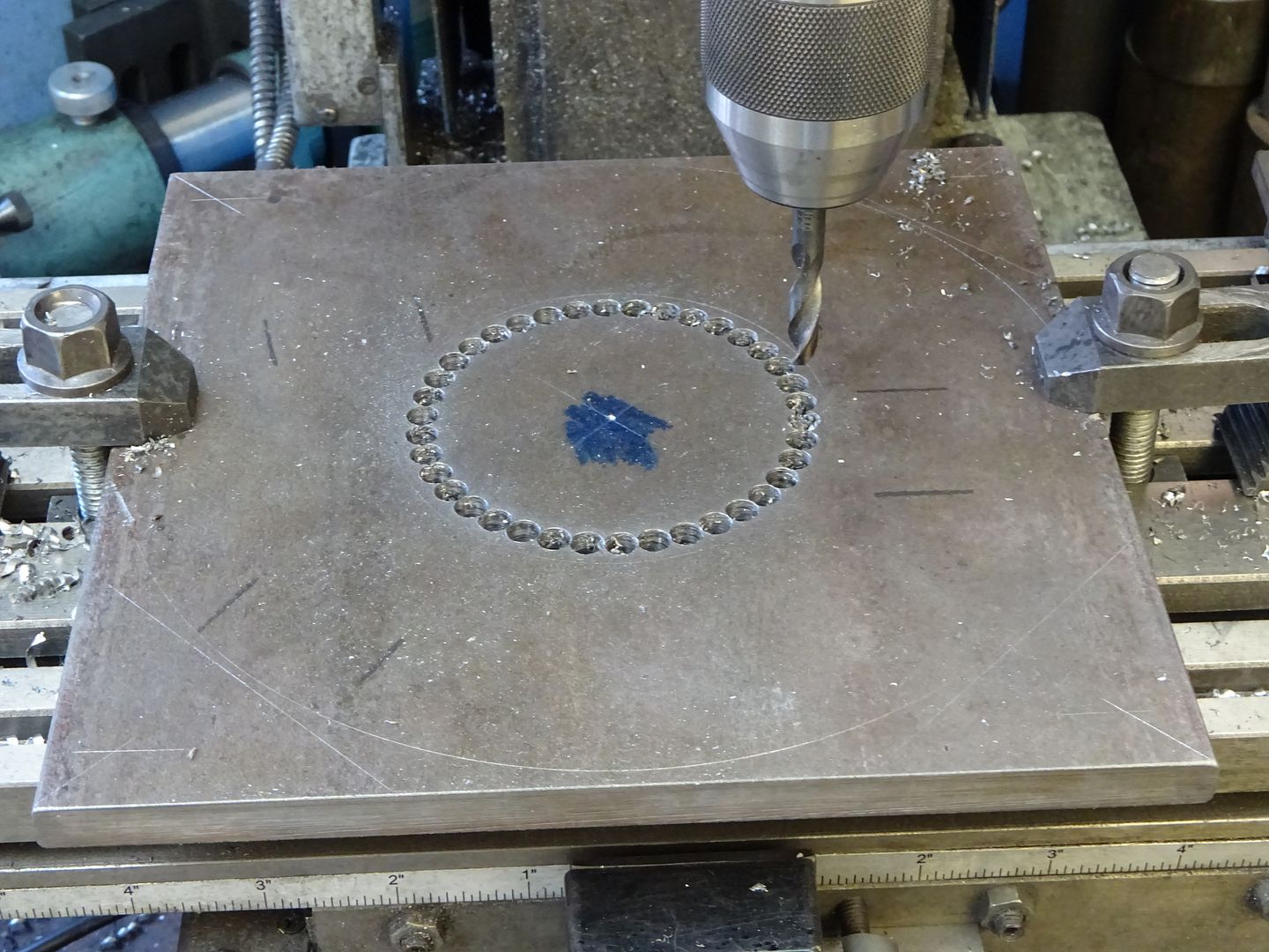
 1129 forum posts 1 photos | Hi All; Got some spare time so thought I would do a bit on my 10V. Thought I would try a pitch circle of 5 holes for the cylinder covers, so watched some YouTube vids and looked pretty simple. Entered 0, 0 for x &y axes after centering up the part with an edge finder, To be on the safe side I am using a sharpie in the chuck not a drill bit, very glad I did! Went into the circle function, set the centre at 0,0; diameter 1.125"; no of holes 5; start angle 000, (3 O'clock); end angle 360 and off we go.. NOT! I only get 4 holes with the 5th back in the starting place! What gives please? DRO is a SINO unit Cheers, Martin
|
| JasonB | 15/03/2018 12:35:44 |
 25215 forum posts 3105 photos 1 articles | Either add 1 to the number of holes or set the ending angle to one space less eg 288 (360-72) |
| Martin King 2 | 15/03/2018 12:42:25 |
1129 forum posts 1 photos | Hi Jason, Thanks! So if I wanted 6 holes I would set 7 or back off the angle by 30 deg? Seems a bit odd and does not happen in the YT videos? Perhaps a SINO DRO quirk? Martin |
| JasonB | 15/03/2018 13:01:16 |
25215 forum posts 3105 photos 1 articles | 60 deg if a 6 hole PCD, finish at 300 or start at 30 and finish at 330 depending on how you want to lay out the set of 6 |
| Martin Kyte | 15/03/2018 13:55:27 |
 3445 forum posts 62 photos | It's doing exactly what it says on the tin. You asked for five holes with the last hole at 0 (or 360 deg). When designing the interface for the DRO the requirement is for a general way of spacing a set number of holes around a circular arc. If you cannot be bothered to calculate the end angle for a full circle of holes you specify an extra one and don't drill the last one because it's already where you put the first one. regards Martin |
| Andrew Johnston | 15/03/2018 13:55:31 |
 7061 forum posts 719 photos | More than a bit odd, positively bizarre! On my DRO (Newall) a PCD is enter centre co-ords, enter diameter, enter number of holes and start angle. The next button push gives the location of the first hole and so on. It'd be a right royal PITA if you had to take into account the actual start and/or finish angles. If I want a large hole I often get rid of the waste by drilling a series of slighly overlapping holes just inside the final diameter. They are usually odd numbers in the range 30 to 40. So start/finish angles would be non-integer numbers. Andrew |
| Nealeb | 15/03/2018 14:15:32 |
| 231 forum posts | My Easson also asks for start/end angles. Makes sense as it allows for holes around part of a circle. It's a question of flexibility against ease of use, I guess, even though most of the time you are going to use the "whole circle" method. I've always worked out the end angle (using the calculator on the DRO if needed!) but I hadn't thought of adding one to the number of holes and using 0 as start and finish. Clever wheeze! |
| JasonB | 15/03/2018 15:34:18 |
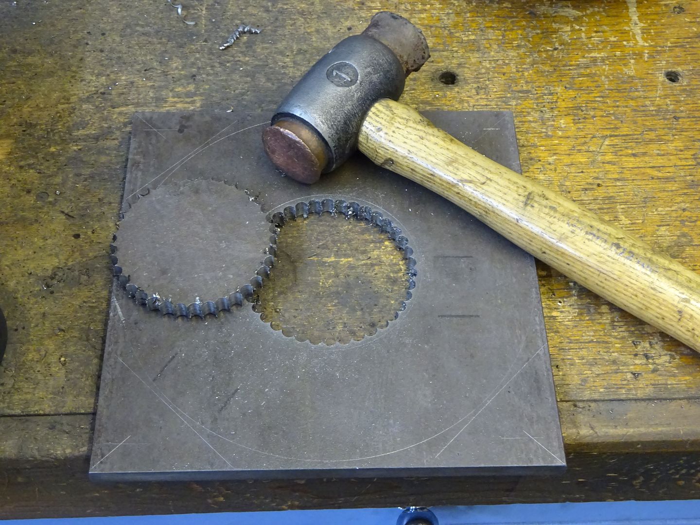
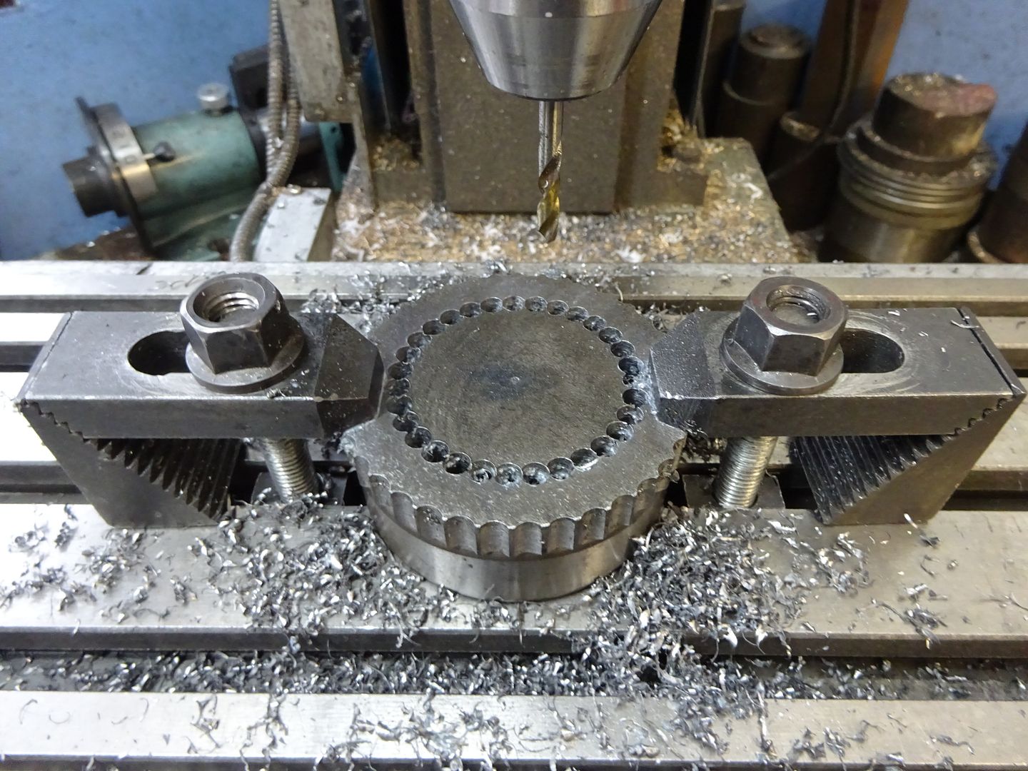
25215 forum posts 3105 photos 1 articles | Yes it does seem a bit odd but once you have found out what the DRO needs entering the first time you do a PCD it becomes second nature after that. As for odd angles when stitch drilling circles I just divide 360 by the number of holes and subtract the answer from 360 to get my ending angle or more often than not see what fits in Alibre and adjust the PCD slightly to suit a common drill size such as 6.0mm and can easily get the angle from that, easy to enter angle to 3 decimal places. Seems to work OK as all that is needed is a tap with a hammer and out drops the waste.
Then you can do it all over again!
|
| Nealeb | 15/03/2018 15:47:36 |
| 231 forum posts | One of the optical scales that came fitted to my Smart and Brown has recently failed, and having now become used to a DRO on a lathe, I've been researching options for replacing/updating. As a result, I've actually read a DRO manual a bit more carefully! I have also used the PCD technique for drill-and-break-out hole-making, but it seems that there is also the option to use the arc ("R" option on the Easson) which automatically sorts out hole overlap, tool diameter, etc, although you might need to do the job using several arcs as I don't think it will quite manage a full circle. Something I'll try out next time I need to do this. On the other hand, I hadn't thought about using CAD to lay out the hole pattern for this; I've been doing sums while standing at the machine which is a little bit fraught. More than one way to skin the cat... |
| Martin King 2 | 15/03/2018 16:09:02 |
1129 forum posts 1 photos | Hi All, Thanks for the advice, all went well with both covers now done and cylinder drilled and tapped. Found that I had not quite machined enough from the underside flange of the standard so the 7BA nuts do not quite sit down flat. Will put it back on the lathe and take off a gnats or two! Looking forward to doing a bit more now that I have got my enthusiasm back! Cheers, Martin |
| Martin Johnson 1 | 15/03/2018 16:30:50 |
| 320 forum posts 1 photos | Martin, If you have one of the Chinese DRO units, (mine is badged Sinpo) then hole PCD's are "interesting" and the Chinglish instructions are not a lot of help either. My experience is largely as you describe. I find the hole centre has to be 0,0, but I can see no reason why this has to be. Most times I can get it all to work, but sometimes it just seems to throw a fit and direct me to very strange places on the work - cannot work out why yet. The moral of all this, run round the PCD with a pointer before you drill (or just mark the surface with a centre drill). Fortunately as with all things digital it is either right or very wrong, so easy to tell. Martin |
| JasonB | 15/03/2018 16:43:26 |
25215 forum posts 3105 photos 1 articles | Should not be a problem getting the PCD to put the ring of holes around any given points, I have done several sets of holes on a single plate of metal. If you can't get that to work then use the absolute to position the spindle over the various ctrs and then switch to incremental, zero X&Y and then do the PCD using the incremental 0-0. |
| Bruno Taylor | 15/03/2018 17:44:26 |
 48 forum posts 14 photos | I had exactly the same problem for my first attempt at a number of holes on a PCD. So l read the instructions again where it clearly said for a circle of n holes enter n+1 as the number of holes required. The DRO logic appears to be first and last hole in the same place. No probs since. Edited By Bruno Taylor on 15/03/2018 17:45:27 |
Please login to post a reply.
Magazine Locator
Want the latest issue of Model Engineer or Model Engineers' Workshop? Use our magazine locator links to find your nearest stockist!
Sign up to our Newsletter
Sign up to our newsletter and get a free digital issue.
You can unsubscribe at anytime. View our privacy policy at www.mortons.co.uk/privacy
Latest Forum Posts
- *Oct 2023: FORUM MIGRATION TIMELINE*
05/10/2023 07:57:11 - Making ER11 collet chuck
05/10/2023 07:56:24 - What did you do today? 2023
05/10/2023 07:25:01 - Orrery
05/10/2023 06:00:41 - Wera hand-tools
05/10/2023 05:47:07 - New member
05/10/2023 04:40:11 - Problems with external pot on at1 vfd
05/10/2023 00:06:32 - Drain plug
04/10/2023 23:36:17 - digi phase converter for 10 machines.....
04/10/2023 23:13:48 - Winter Storage Of Locomotives
04/10/2023 21:02:11 - More Latest Posts...
- View All Topics
Support Our Partners


Shopping Partners
Subscription Offer

Latest "For Sale" Ads
- Reeves** - Rebuilt Royal Scot by Martin Evans
by John Broughton
£300.00 - BRITANNIA 5" GAUGE James Perrier
by Jon Seabright 1
£2,500.00 - Drill Grinder - for restoration
by Nigel Graham 2
£0.00 - WARCO WM18 MILLING MACHINE
by Alex Chudley
£1,200.00 - MYFORD SUPER 7 LATHE
by Alex Chudley
£2,000.00 - More "For Sale" Ads...
Latest "Wanted" Ads
- D1-3 backplate
by Michael Horley
Price Not Specified - fixed steady for a Colchester bantam mark1 800
by George Jervis
Price Not Specified - lbsc pansy
by JACK SIDEBOTHAM
Price Not Specified - Pratt Burnerd multifit chuck key.
by Tim Riome
Price Not Specified - BANDSAW BLADE WELDER
by HUGH
Price Not Specified - More "Wanted" Ads...
Get In Touch!
Do you want to contact the Model Engineer and Model Engineers' Workshop team?
You can contact us by phone, mail or email about the magazines including becoming a contributor, submitting reader's letters or making queries about articles. You can also get in touch about this website, advertising or other general issues.
Click THIS LINK for full contact details.
For subscription issues please see THIS LINK.
Digital Back Issues


Donate

 Register
 Log-in
Model Engineer Magazine
- Percival Marshall
- M.E. History
- LittleLEC
- M.E. Clock

ME Workshop
- An Adcock
- & Shipley
- Horizontal
- Mill

Subscribe Now
- Great savings
- Delivered to your door

Pre-order your copy!
- Delivered to your doorstep!
- Free UK delivery!
All Forum Topics > Beginners questions > Pitch Circle on DRO problem