Forum sponsored by:

new Harrison L6 mk3
| james huxstep | 11/01/2017 20:26:40 |
 91 forum posts 24 photos | Ok so the eagle has landed!!!i have a new used harrison l6 mk3 and what a beast! ive noticed there is no graduations on the main apron handweel? I would like to take it apart as much as i can to give it a clean etc as there is a lot of brass swarf mixed in with grease etc. Can i take the main screwcutting leadscrew out to de grease and re grease etc? i cant find a spindle lock to remove the 3 jaw , dont know if it has one, ive seen the piece of wood trick and open the jaws so it fouls the the wood whilst pulling the belt round? like to do an oil change on the seal gear chamber.[dont know what oil to replace it with though] what sort of oils do i need for the various nipples, and grease required for leadscrews [topslide and crosslide and screwcutting leadscrew] is there a saddle stop for this lathe to do a~b turning? sorry for all the questions thanks
james Edited By james huxstep on 11/01/2017 20:29:11 |
| Ady1 | 11/01/2017 20:41:42 |
 6137 forum posts 893 photos | That was quick, the boxford only fell off the lorry about 5 days ago
|
| james huxstep | 11/01/2017 20:43:50 |
91 forum posts 24 photos | yeah i know, ive been watching a few, only got a small gap before going back to work |
| Graham Wharton | 11/01/2017 21:10:21 |
| 149 forum posts 48 photos | Hi James, I have the L6 Mk3 lathe also. Its quite a machine as youre going to find out. It is normal to have no graduations on the saddle handwheel unfortunately. Harrison sold a Micrometer saddle stop, which you can use to accurately position the saddle (within the travel limits of the stop).
At the right hand end of the leadscrews there is a bearing block that houses the end bearings for the clutch engagement shaft, leadscrew and feedscrew. If you undo the two large allen bolts, position the saddle fully to the left, then pull the bearing block slightly forward to release its locating dowels, the bearing block can be slid off to the right to release the ends of the lead/feed screws. I believe (although ive not done this myself) that if you disengage the feed nut via the handle, the leadscrew can be slid out through the saddle and free of the machine. It should just pull out of the end of the gearbox. Personally if its just for cleaning and regreasing I would leave in situ and just clean in place. The clutch engagement shaft requires correctly aligning on the splines when refitting, and there is also a ball bearing that will drop out when you loosen the tension on the bearing block/clutch engagement shaft that keeps the clutch engaged/disengaged properly. There is no spindle lock, however if you put the lathe into low gear, you should be able to get plenty of purchase on the locking ring to remove the chuck (I'm assuming yours has the L00 taper). The quick change gearbox takes an ISO 220 Grade Mineral Oil. Note that the gearbox contains brass and bronze bushings that can be attacked by certain EP additives found in standard gearbox oils so be careful about using the correct type of oil. Harrison recommend Shell Vitrea 72, which has since been renamed to Shell Morlina S2 B220. Harrison recommend for the headstock gearbox to use Shell Tellus 33 Hydraulic Oil, which has since been renamed to Shell Tellus S2 M68. Both of the above oils are available on ebay in small quantities. Harrison also recommend the same Shell Tellus 33 (Tellus S2 M68) to use on the ways, saddle, tailstock etc.. Its not a specific slideway oil, but has anti wear, anti rust and anti oxidation properties so will work just fine. The only place you should be using grease is in the bearing nipples on the motor. Hope this helps. Graham
|
| Alan Waddington 2 | 11/01/2017 21:16:11 |
| 537 forum posts 88 photos | When I got my L5A. I phoned Harrison (600 group) and asked if they could sell me a manual for it. A very nice man sent me a photocopied and spiral bound copy F.OC According to the serial number my lathe came out of Harrison in 1958, so would have been at least40 years old at the time.....impressive service or what !
Edited By Alan Waddington 2 on 11/01/2017 21:16:40 |
| Graham Wharton | 11/01/2017 21:17:04 |
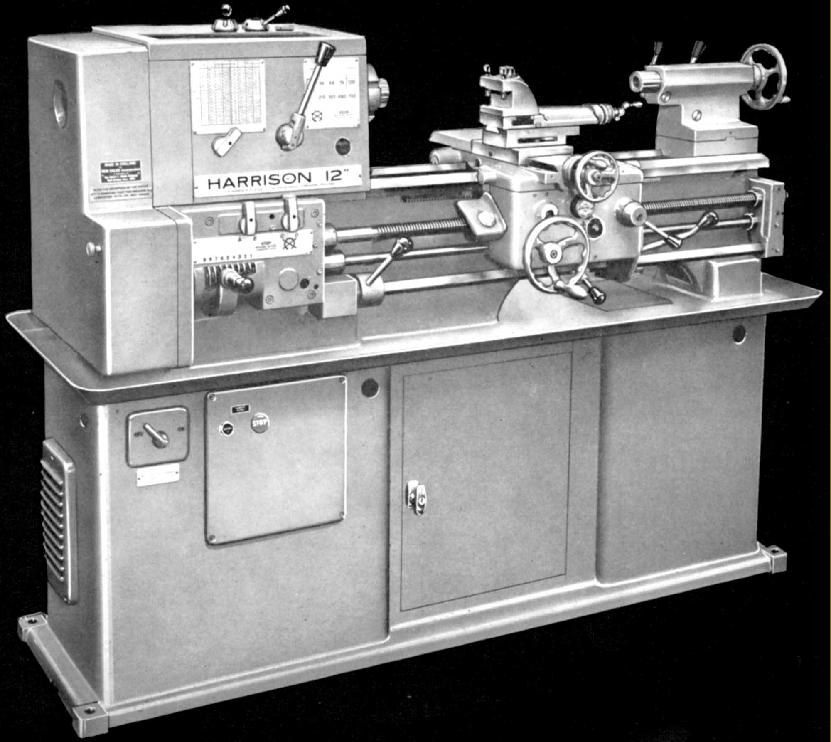
| 149 forum posts 48 photos | Just to add a bit more info about saddle stops, This is a photo of my L6 with the standard saddle stop fitted to the bed just to the right of the saddle.
And this photo shows the micrometer saddle stop fitted to the bed also to the right of the saddle.
Both of the stops can be fitted either on the left or the right of the saddle. They butt up against the stops that are fitted to either side of the saddle. Hope this helps Graham |
| james huxstep | 11/01/2017 22:09:59 |
91 forum posts 24 photos | ok thanks
ive got something else that came with it il take a photo of it tomoz.a 2"dia cylindical thing with a hole right through it roughly 4" long, and what looks like a slot milled down the side of it.it also has a smaller hole off centre from the main bore, which is countersunk. looking at your second picture:10" below the '12' on 'harrison 12' on the bottom longitudinal shaft there is a handle with a black ball on it. i havent got this. i have got the metal cylindrical thing that the handle screw into, but with no handle, and no female thread to screw it into.
thanks
james |
| SteveI | 11/01/2017 22:11:39 |
| 248 forum posts 22 photos | Posted by james huxstep on 11/01/2017 20:26:40: ive noticed there is no graduations on the main apron handweel?
Thats nothing a nice DRO wont solve for you.
Congrats with the new lathe. |
| Graham Wharton | 11/01/2017 22:21:44 |
| 149 forum posts 48 photos | Thats the second clutch engagement lever, the first being on the right hand side of the saddle. Both operate in the same way. It just means you have to operate the clutch with your right hand, and dont have the option of left handed operation. I don't know if the left hand lever was an option or standard fit. Have you checked by feeling round the back of the round bush to see if it has maybe been fitted 180 degrees out of alignment and does have a threaded hole to receive a lever. A replacement lever should be easily made. That round bush by the way has a grub screw which stops it from sliding along the square shaft. If that grub screw is loosened and the round bush does indeed slide away from the gearbox, then thats the location that the small ball bearing will fall out from so just be aware if you are fiddling in that area. The ball bearing is sprung and sits between the round bush and the gearbox. It rests in two small dimples machined in the gearbox output flange to provide a way of securing the clutch lever in the on or off position. If you pull the clutch lever up to engage drive and it doesnt stay fully up and the handle drops back down slightly it can cause the clutch to slip. Its a common problem and indicates that someone has taken it to bits and has forgotten to refit the ball bearing that fell out. |
| james huxstep | 11/01/2017 22:34:51 |
91 forum posts 24 photos | Also i need an inverter for it, as i dont have 3 phase. ive been told a cub transwave inverter? what power are these motors? thanks
james |
| james huxstep | 11/01/2017 23:11:39 |
91 forum posts 24 photos | ok ive done some research and i actually thing, my one is a harrison L6 mk1, not mk3 james |
| Graham Wharton | 11/01/2017 23:12:48 |
| 149 forum posts 48 photos | According to the manual (which i sent you a link to in a PM by the way) it says that the single speed ones are 3hp and the dual speed ones are 3hp/1.5hp depending on whether low/high speed is selected, although there were a range of motors fitted depending on the location the lathe was sold. It would probably be best to swing open the motor mounting plate at the rear of the base and take a look at the motor data plate to be sure. One thing you should be aware of though, if it is an original motor in there, then they are wired for 415VAC 3 phase star configuration and are not reconfigurable for 240VAC 3 phase delta operation as you would get out of your inverter. (At least mine wasnt reconfigurable for delta operation) I run mine from a 240VAC inverter, but I stripped the motor down, and did some modifications to the windings to allow it to run in 240VAC delta configuration instead of 415VAC star. (Basically brought out the internal star point to external connections) I have no idea how well the lathe would run if you attempted to run a 415VAC star configuration motor on a 240VAC delta inverter output. Perhaps someone else could chime in here. If the answer is that it wont run well, then to run via an inverter, your two options are to modify the motor to bring out the star point to allow delta operation (not easy), or replace the motor with a 3 phase motor that can be configured for 240V delta. Another couple of things to bear in mind while were talking about electrics 1. The suds pump is 3 phase aswell, although mine was a dual voltage motor which is easily re-configured to run from a 240VAC 3 phase supply as you would get from an inverter. I run both the lathe motor and suds pump motor from a single inverter without any issues (I did leave the suds pump wired in via the suds pump switch, so I can choose to start the lathe with suds on or suds off by using the switch.... I try to avoid switching the suds pump on while the inverter is running the main motor, as all the reading material would suggest that turning loads on/off a loaded inverter could damage the inverter) 2. If the lathe is fitted with a light, then the light will probably be fed from the Phase 1 of the 3 phase supply. There is a transformer in the lamp switch box bolted to the back of the headstock which contains a transformer which is probably expecting to see 415VAC single phase input. The transformer converts the voltage to a low voltage (cant remember off hand but 28V sounds familiar). The wiring on the transformer can be altered if the input voltage is not 415VAC to ensure that the bulb voltage is correct. On my lathe, I fitted a 3 pin UK plug and lead to the lamp and powered directly from a mains socket. I reconfigured the transformer inside the lamp housing to accept 240VAC input and thus the lamp is now independent of the inverter input. 3. If you are running from an inverter it is probably worth re-wiring and bypassing the control panel start/stop buttons on the front of the lathe. You don't want any switchgear between the inverter and the motors. I start/stop the lathe from the inverter controls. Its not as fiddly as you might imagine as your lathe has a clutch so you can start the motor from the inverter and then start/stop the chuck using the mechanical clutch, then when your work is done, stop the lathe from the inverter. Some things to think about anyway. If you're not up to scratch on 3 phase electrics, I would get an industrial sparky to drop in to take a look at your setup. |
| Graham Wharton | 11/01/2017 23:16:21 |
| 149 forum posts 48 photos | Ahh yes, the Mk1 is indeed different. It has only one clutch lever and that is above the headstock, not down by the saddle like in the Mk3. I assume you have checked out **LINK** Graham |
| james huxstep | 11/01/2017 23:44:55 |
91 forum posts 24 photos | Yeah, thats where i got my info from. right well ive already dismantled the light, got that running on 230v supply all good.The motor i will check out tomoz. Yeah the fella at home and workshop, suggested i would need a new switch.Will the motor say on it which 3 phase wiring star/delta it is wired in? james |
| Graham Wharton | 12/01/2017 11:46:07 |
| 149 forum posts 48 photos | James, I would recommend taking a photo of the motor name plate if you can find it. Also remove the little cover where the wiring enters the motor and take a photo of the terminals you find inside. Post the photos here. You are looking for any markings on the name plate suggesting it operates at 240VAC aswell as 415VAC, i.e dual voltage. Here is an example of a motor name plate indicating it is dual voltage.
You can see it is a 5hp 3.7kW 50Hz motor. When wired in Delta mode (indicated by traiangle symbol) it works at 220VAC and will draw 13.87Amps or when wired in Star mode (indicated by an upside down Y) it will work at 380VAC and will draw 8.03Amps. It also shows you how to configure the links on the 6 posts/terminals to enable each mode. In my experience however, motors of the vintage you will find in your lathe will have less information on the name plate, but the important details such as the voltages supported and the full load amps should be present. In the motor wiring terminals you are looking for 6 posts/terminals + earth, which suggest it could possibly be switched between delta and star, as opposed to 3 posts/terminals + earth which would suggest it is hard wired for star (or delta). Graham |
| james huxstep | 13/01/2017 13:41:38 |
91 forum posts 24 photos | Ok il get on that. Because its on a tray that flops out, do i have to disconnect the v belts before opening the pan? If so how do i go about doing that? From the left hand side that opens exposing the gears? Thanks James |
| Graham Wharton | 13/01/2017 14:26:48 |
| 149 forum posts 48 photos | Hi James, You can remove the grill on the left hand end of the base which should give you some visibility of the motor and belting. You may be able to get a camera in there without disturbing the belts. If you can't then you will need to swing the motor out on the mounting pan. If you look at the motor pan from the back of the lathe, there should be a large screw/bolt on one side that you can turn to move the motor pan in and out. There may be a smaller bolt locking the pan on the other side which you may need to remove before you can move the pan. The tension on the belts is set by moving this pan in and out using the main winding bolt. Before you release the tension on the belts, make a note of how tight the current belts are so you can reset them accordingly. You should be able to move the motor pan in or out sufficiently to allow you to unhook the drive belts from the motor pulley through the access hatch in the left hand end of the base. Once you have done this, the motor pan can be wound fully out. Beware at some point, you will reach the end of the travel on the large winding screw and the motor pan will drop. ITS HEAVY!!! get ready for it dropping. Hope this helps Graham Edited By Graham Wharton on 13/01/2017 14:28:29 |
| james huxstep | 14/01/2017 15:01:08 |
91 forum posts 24 photos | Ok thanks Ive had quick look, and it looks like the original motor. If when i get out and it is wired in delta i will probably get a single phase version for it. Do you have to go up in horsepower when buying a single phase version? Obviously shaft diameter feet spacing has to be correct, and it needs to be same spindle speed or near as dam it. Thanks James Edited By james huxstep on 14/01/2017 15:02:13 |
| Alan Waddington 2 | 14/01/2017 17:29:51 |
| 537 forum posts 88 photos | It's dead easy to dig the Star point out on those old Harrison motors, you can then run them from an inverter. Lots of benefits of doing it that way, variable speed control, Easy forward and reverse switching, E stop etc. Did an L5a recently, so know it works perfectly, and truly easy to do. |
| james huxstep | 14/01/2017 18:46:33 |
91 forum posts 24 photos | Ok cool, well il take a photo of it tomoz, i suppose if i can get it to run with inverter, it would be easier to get the suds pump working aswell, being three phase.i take it i wouldnt have to change the switches if i could get a three phase feed in. Cheers James |


Please login to post a reply.
Magazine Locator
Want the latest issue of Model Engineer or Model Engineers' Workshop? Use our magazine locator links to find your nearest stockist!
Sign up to our Newsletter
Sign up to our newsletter and get a free digital issue.
You can unsubscribe at anytime. View our privacy policy at www.mortons.co.uk/privacy
Latest Forum Posts
- *Oct 2023: FORUM MIGRATION TIMELINE*
05/10/2023 07:57:11 - Making ER11 collet chuck
05/10/2023 07:56:24 - What did you do today? 2023
05/10/2023 07:25:01 - Orrery
05/10/2023 06:00:41 - Wera hand-tools
05/10/2023 05:47:07 - New member
05/10/2023 04:40:11 - Problems with external pot on at1 vfd
05/10/2023 00:06:32 - Drain plug
04/10/2023 23:36:17 - digi phase converter for 10 machines.....
04/10/2023 23:13:48 - Winter Storage Of Locomotives
04/10/2023 21:02:11 - More Latest Posts...
- View All Topics
Support Our Partners


Shopping Partners
Subscription Offer

Latest "For Sale" Ads
- Reeves** - Rebuilt Royal Scot by Martin Evans
by John Broughton
£300.00 - BRITANNIA 5" GAUGE James Perrier
by Jon Seabright 1
£2,500.00 - Drill Grinder - for restoration
by Nigel Graham 2
£0.00 - WARCO WM18 MILLING MACHINE
by Alex Chudley
£1,200.00 - MYFORD SUPER 7 LATHE
by Alex Chudley
£2,000.00 - More "For Sale" Ads...
Latest "Wanted" Ads
- D1-3 backplate
by Michael Horley
Price Not Specified - fixed steady for a Colchester bantam mark1 800
by George Jervis
Price Not Specified - lbsc pansy
by JACK SIDEBOTHAM
Price Not Specified - Pratt Burnerd multifit chuck key.
by Tim Riome
Price Not Specified - BANDSAW BLADE WELDER
by HUGH
Price Not Specified - More "Wanted" Ads...
Get In Touch!
Do you want to contact the Model Engineer and Model Engineers' Workshop team?
You can contact us by phone, mail or email about the magazines including becoming a contributor, submitting reader's letters or making queries about articles. You can also get in touch about this website, advertising or other general issues.
Click THIS LINK for full contact details.
For subscription issues please see THIS LINK.
Digital Back Issues


Donate

 Register
 Log-in
Model Engineer Magazine
- Percival Marshall
- M.E. History
- LittleLEC
- M.E. Clock

ME Workshop
- An Adcock
- & Shipley
- Horizontal
- Mill

Subscribe Now
- Great savings
- Delivered to your door

Pre-order your copy!
- Delivered to your doorstep!
- Free UK delivery!
All Forum Topics > Manual machine tools > new Harrison L6 mk3