Forum sponsored by:

Simple Mill Engine - Stewart Hart ME.4460 - Part CP11
| Bruce Edney | 24/01/2015 04:39:02 |
 167 forum posts 53 photos | Hi I have just started making this little engine and can not find anything about this part mentioned except in Fig 3 I take it that this is just a cap and is glued in place using Loctite. Would it also benefit from a small hole to avoid compression issues at the top of the valve piston? Thanks for an awesome project Regards Bruce Edney |
| Stewart Hart | 24/01/2015 08:00:50 |
 674 forum posts 357 photos | Hi Bruce
Yes its just a simple cap a tight fit and fixed with supper glue, in fact the engine will work perfectly without it, its just their to tidy things up. It doesn't need a vent hole the exhaust port does that job. Thanks for you interest in the engine, there have been quite a lot made, the design is very robust to the odd mistake and is ideal for a beginner. Cheers Stew Edited By Stewart Hart on 24/01/2015 08:04:14 |
| Bruce Edney | 24/01/2015 18:24:12 |
167 forum posts 53 photos | Thanks Stew |
| Bruce Edney | 16/03/2015 07:29:26 |
167 forum posts 53 photos | Hi Stew I have another question. I know the dimensions are not critical but just trying to get it looking right. In the photos and the drawing of the base it shows a significant amount of material at the crankshaft end however the measurements don't stack up. Should the overall base length actually be about 250-260mm? Cheers Bruce PS. I have had the engine running and after fixing a few engineering issues (engineer not design) it runs like a dream. Edited By Bruce Edney on 16/03/2015 07:29:56 |
| JasonB | 16/03/2015 07:50:33 |
 25215 forum posts 3105 photos 1 articles | The 4 mounting holes should be 225mm ctrs and the overall length 240mm Check your messages Edited By JasonB on 16/03/2015 08:04:11 |
| Stewart Hart | 16/03/2015 08:08:04 |
674 forum posts 357 photos | Hi Bruce Pleased to her you've got the engine running. I've measured up the base of my engine, as you have guessed I didn't follow my own drawings You can see this in these photos. Sorry if I've confused the issue, but I sometimes don't actually publish what I have made as I try to and correct/simplify things that I've found out in the process. Cheers Stew
|
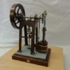
| Dullnote | 28/10/2017 17:38:31 |
 94 forum posts 29 photos | Hi hope this is the correct thread for this, couple of photos of my attempt to construct this engine, I have never used a lathe from leaving school and I plan on retiring in two years so you can work out the sums. This is the start of my further education, the engine is still to be completed and is in rough stages, the threaded bar to be cut to correct length, washers added. May not be to the same high standard I see on this forum, but I am pleasantly please with me efforts, when I get it completed and running I will then spend time making it look good Best thing about it is, I have had a great time leaning new skills. Just thought I would share
|
| Neil Wyatt | 28/10/2017 18:06:29 |
 19226 forum posts 749 photos 86 articles | Looks good from over here Neil |
| Stewart Hart | 30/10/2017 07:21:05 |
674 forum posts 357 photos | Posted by Neil Wyatt on 28/10/2017 18:06:29:
Looks good from over here Neil Looks very good from her Nice work Jim Its always great to see one of these engines being made by a beginner, as it was designed as a beginners engine, there must have been quite a lot made by now. Can't wait to see a picture of the finished engine or even a video of it running Cheers Stew |
| SillyOldDuffer | 30/10/2017 10:47:33 |
| 10668 forum posts 2415 photos | I'm building my second example at the moment. The engine works, is reasonably tolerant of mistakes, and has some interesting challenges without being baffling. I enjoyed making the first one.
This time it's a beginner+ project in that I'm being much more fussy about finish and building to plan. The idea is to compare the two builds to see where I've improved, and - more important - identify which skills still need attention. Judging by the reject rate, I have a long way to go! I'm experimenting with another approach to construction too. First time, I made the parts one at a time, each starting as a lump of metal and only downing tools when the part was complete. Second time round I'm making several parts in parallel and not necessarily finishing all machining before moving on to another part. The disadvantage of the first method was making mistakes because I got bored, The disadvantage of the second method is I make mistakes because I misremember what needs doing next. It appears I'm better at making mistakes than engines! Dave |
| roy entwistle | 30/10/2017 11:00:20 |
| 1716 forum posts | Dave The man who didn't make mistakes, didn't make anything. Also experience is built on mountains of scrap Roy |
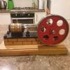
| Dullnote | 27/01/2018 20:06:04 |
94 forum posts 29 photos |
|
| Jim Nic | 27/01/2018 20:56:46 |
 406 forum posts 235 photos | That's looking very tidy Jim. Do she run yet? Jim |
| Dullnote | 27/01/2018 22:57:14 |
94 forum posts 29 photos | Not yet still got eccentric to fit. The flywheel does turn the crank around and everything does what it should do but feel unit is tight, think I will need to tweak it a bit to get smooth movement but plan to do that when everything is fitted, hope to get some workshop time tomorrow Jim |
| Stewart Hart | 28/01/2018 07:09:36 |
674 forum posts 357 photos | Hi Duffer Sorry I missed your post on 30/10/17 I was on holiday at the time and got behind with following the forum. Your build is looking good, have you got her running ?. Stew
Hi Jim That,s looking good too, best way to shake out the tight spots is to loosen all the screws, then tighten them up one by one any screw that causes it to bind needs investigating and the cause fixing. Look forward to seeing the completed engines and a video if posible Cheers Stew
|
| Hopper | 28/01/2018 11:50:00 |
 7881 forum posts 397 photos | Posted by Stewart Hart on 16/03/2015 08:08:04:
Stewart, on the brass bands around the wooden lagging strips on the cylinder, are those brass rivets' holes drilled into the metal cylinder, or are they just into the wood? Also, where's a good place to buy the graphite packing for the piston ring and glands? |
| SillyOldDuffer | 28/01/2018 12:38:49 |
| 10668 forum posts 2415 photos | Posted by Stewart Hart on 28/01/2018 07:09:36:
Hi Duffer Sorry I missed your post on 30/10/17 I was on holiday at the time and got behind with following the forum. Your build is looking good, have you got her running ?. Stew ...Stew
Yes she goes but I left off the inner brass washers whilst pinning the crankshaft and bent it slightly on re-assembly. Although the valve is rather stiff and the crankshaft's bent the engine runs given enough air. Now waiting for me to make another crankshaft and ease the valve where it's binding on the guide. Then beautifying. Your paint and wood work photos have given me something to aspire to. The engine build is temporarily paused while I play with a computer project but it's still top of my metal bashing list. Dave |
| Stewart Hart | 28/01/2018 13:02:06 |
674 forum posts 357 photos | Posted by Hopper on 28/01/2018 11:50:00:
Posted by Stewart Hart on 16/03/2015 08:08:04:
Stewart, on the brass bands around the wooden lagging strips on the cylinder, are those brass rivets' holes drilled into the metal cylinder, or are they just into the wood? Also, where's a good place to buy the graphite packing for the piston ring and glands? The method I used on the brass banding wasn't one of my better ideas I used two way sticky tape the rivets are just dummy, but the darn stuff starts to peal off and I have to press it back down, for the follow on engine I drilled through the banding into the cylinder and used some small M2 dome headed cap screws to fasten it down, you can get the screws from model fixings http://www.modelfixings.co.uk/ I had terrible trouble the first time I tried to clad a cylinder then someone told the trick of first gluing the batons with copydex to a piece of cotton material then cut to shape and fix the whole lot to the cylinder, the batons are coffee sterers. You can get the graphite from Macc Models or Blackgates but you could use ptfe thread tape that you get from plumbers merchants just twist it into a string and use a graphite packing works just as well. Hope this helps Stew |
| Stewart Hart | 28/01/2018 13:04:33 |
674 forum posts 357 photos | Posted by SillyOldDuffer on 28/01/2018 12:38:49:
Posted by Stewart Hart on 28/01/2018 07:09:36:
Hi Duffer Sorry I missed your post on 30/10/17 I was on holiday at the time and got behind with following the forum. Your build is looking good, have you got her running ?. Stew ...Stew
Yes she goes but I left off the inner brass washers whilst pinning the crankshaft and bent it slightly on re-assembly. Although the valve is rather stiff and the crankshaft's bent the engine runs given enough air. Now waiting for me to make another crankshaft and ease the valve where it's binding on the guide. Then beautifying. Your paint and wood work photos have given me something to aspire to. The engine build is temporarily paused while I play with a computer project but it's still top of my metal bashing list. Dave Hi Dave Pleased you got a runner we all go through a learning curve no mater what we attempt, the important thing is to learn from mistakes and don't give up.
Stew
|
| Hopper | 28/01/2018 13:08:28 |
7881 forum posts 397 photos | Posted by Stewart Hart on 28/01/2018 13:02:06:
Posted by Hopper on 28/01/2018 11:50:00:
Posted by Stewart Hart on 16/03/2015 08:08:04:
The method I used on the brass banding wasn't one of my better ideas I used two way sticky tape the rivets are just dummy, but the darn stuff starts to peal off and I have to press it back down, for the follow on engine I drilled through the banding into the cylinder and used some small M2 dome headed cap screws to fasten it down, you can get the screws from model fixings http://www.modelfixings.co.uk/ Thanks. LOL, trust me to ask the awkward question! I've used the rolled thread tape dodge I don't know how many times on full-sized steam plant years ago, glad to see at least some of my skills transfer across to the smaller scale stuff. At least it was a step forward from my old boilerhouse foreman's dodge of pulling a string off the floor mop and using it to pack a leaky gland with. Edited By Hopper on 28/01/2018 13:10:24 |


Please login to post a reply.
Magazine Locator
Want the latest issue of Model Engineer or Model Engineers' Workshop? Use our magazine locator links to find your nearest stockist!
Sign up to our Newsletter
Sign up to our newsletter and get a free digital issue.
You can unsubscribe at anytime. View our privacy policy at www.mortons.co.uk/privacy
Latest Forum Posts
- *Oct 2023: FORUM MIGRATION TIMELINE*
05/10/2023 07:57:11 - Making ER11 collet chuck
05/10/2023 07:56:24 - What did you do today? 2023
05/10/2023 07:25:01 - Orrery
05/10/2023 06:00:41 - Wera hand-tools
05/10/2023 05:47:07 - New member
05/10/2023 04:40:11 - Problems with external pot on at1 vfd
05/10/2023 00:06:32 - Drain plug
04/10/2023 23:36:17 - digi phase converter for 10 machines.....
04/10/2023 23:13:48 - Winter Storage Of Locomotives
04/10/2023 21:02:11 - More Latest Posts...
- View All Topics
Support Our Partners


Shopping Partners
Subscription Offer

Latest "For Sale" Ads
- Reeves** - Rebuilt Royal Scot by Martin Evans
by John Broughton
£300.00 - BRITANNIA 5" GAUGE James Perrier
by Jon Seabright 1
£2,500.00 - Drill Grinder - for restoration
by Nigel Graham 2
£0.00 - WARCO WM18 MILLING MACHINE
by Alex Chudley
£1,200.00 - MYFORD SUPER 7 LATHE
by Alex Chudley
£2,000.00 - More "For Sale" Ads...
Latest "Wanted" Ads
- D1-3 backplate
by Michael Horley
Price Not Specified - fixed steady for a Colchester bantam mark1 800
by George Jervis
Price Not Specified - lbsc pansy
by JACK SIDEBOTHAM
Price Not Specified - Pratt Burnerd multifit chuck key.
by Tim Riome
Price Not Specified - BANDSAW BLADE WELDER
by HUGH
Price Not Specified - More "Wanted" Ads...
Get In Touch!
Do you want to contact the Model Engineer and Model Engineers' Workshop team?
You can contact us by phone, mail or email about the magazines including becoming a contributor, submitting reader's letters or making queries about articles. You can also get in touch about this website, advertising or other general issues.
Click THIS LINK for full contact details.
For subscription issues please see THIS LINK.
Digital Back Issues


Donate

 Register
 Log-in
Model Engineer Magazine
- Percival Marshall
- M.E. History
- LittleLEC
- M.E. Clock

ME Workshop
- An Adcock
- & Shipley
- Horizontal
- Mill

Subscribe Now
- Great savings
- Delivered to your door

Pre-order your copy!
- Delivered to your doorstep!
- Free UK delivery!
All Forum Topics > Model Engineer. > Simple Mill Engine - Stewart Hart ME.4460 - Part CP11