Forum sponsored by:

Myford VMB Mill conversion to CNC
| Viv Watts | 17/01/2015 20:47:43 |
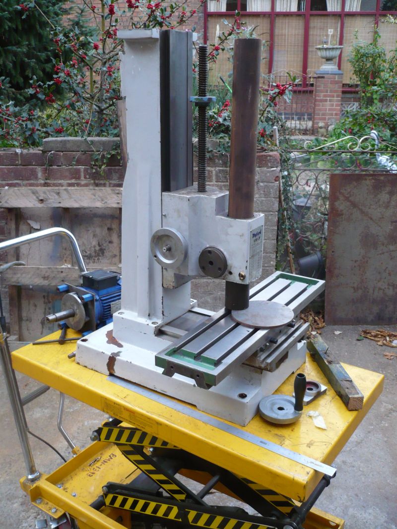
 7 forum posts 17 photos | Thought this may be of interest to other members who might have a Myford VMB milling machine and how I converted it to CNC. The machine has developed over time. Here is its current state of play... The Blue bits are mostly the added items
It has digital readouts for X Y and Z1 and Z2. This was the original task. They are all of the chinese scale variety. The X, Z1 and Z2 being commercial designed for the job scales. The Y axis was a modified LIDL scale which works fine. The next task was to monitor spindle speed. The Myford variable speed control was fine but looking up the conversion chart was tedious. A chinese digital frequency readout (£8) was purchased and with little modification could display RPM. A segemented disc on the top main drive pulley provided the pulses. The next task was to power the Z axis as the gear ratio o nthe hand whell was very high. I actually used a motor for a bread maker which worked fine but was later replace by a stepper drive for CNC (see later).
You can see above modifications to the hand wheel (Red) and a counter balance ball (when it spins fast it will shake without it). Nexit is a home made Z axis jog/drive control knob (black on blue box). Make to look like normal machine tool knob. It seem natuaral to reach up to drive the z axis. Of interest may be the red aluminium ring around the drive spindle to aid gripping to tighten chucks etc. Just behind the z axis hand wheel is a blue cover for the Z axis micro switches which use the z axis DRO to hold slidable limits for up and down but rearly used.
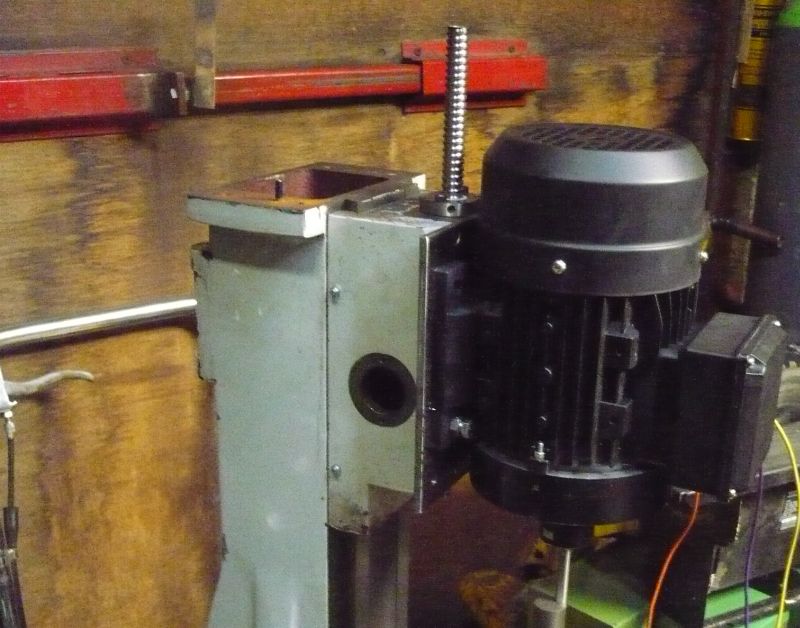
Above is the Z axis drive mechanism. A pulley is fitted directly on the hand wheel shaft. The motor is mounted at the rear.
Above is Z drive belt cover fitted (made out of MDF).
And a rear view of the z axis motor cover with drive cable.
Above is X axis drive assembly. The original bearing casting is replace with an aluminium plate. A oilite bearing is added. Picture shows stepper and to the rear the X and Y jog joystick. Drive to the hand wheel is through the two screews which engage into a drive pulley. The hand wheel knob is removed for safety.
A cover keeps the muck out. The Y axis drive is achieved with a stepper mounted under the bed (just enough clearance with the raising feet. Again a cover to keep the muck out which was CNC'ed on the machine itself.
Rear view of the machine showing jucntion box for all X Y and Z cables X axis limit switches, X axis scale signals, Y axis limit switch cable routing.
The above shows the original myford VFD motor drive (center right black box) cabinet. The CNC controller board from planet CNC top left. Three stepper motor driver units top right. Bottom is stepper power supply with temperature sensing board added to control fan in supply an two mounted on cabinet door. Viv |
| Michael Gilligan | 17/01/2015 20:56:00 |
 23121 forum posts 1360 photos | Very tidy job, Viv MichaelG. |
| John Stevenson | 17/01/2015 21:21:13 |
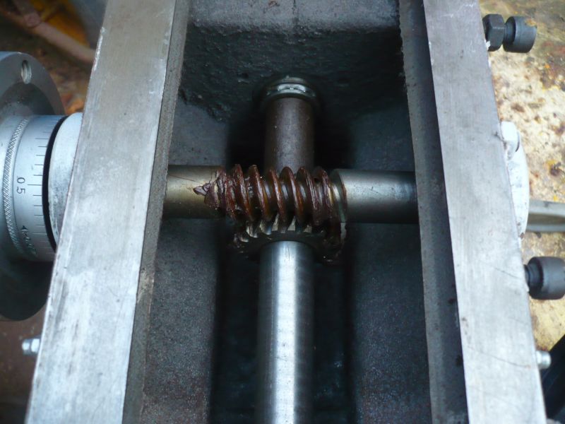
 5068 forum posts 3 photos | So the Z axis is still uses the worm drive and original acme screw ?
Are X and Y on ball screws ?
Edited to read semi-English. Edited By John Stevenson on 17/01/2015 21:22:01 |
| Muzzer | 17/01/2015 21:23:49 |
 2904 forum posts 448 photos | Nice job Viv. Is it cutting metal now? Mach 3? Murray |
| Viv Watts | 18/01/2015 11:58:53 |
7 forum posts 17 photos | Still has original screws in all axis. Considering how to add anti-backlash nuts. No its not Mach 3. I use a self contained CNC controller and connect via USB. http://www.planet-cnc.com/ Yes it has been cutting metal. After parts for itself then first project was a probe.
|
| John Haine | 18/01/2015 16:15:11 |
| 5563 forum posts 322 photos | Nice! Thanks for posting.
john. |
| John Stevenson | 19/01/2015 16:07:44 |
5068 forum posts 3 photos | I am part way thru one but with a difference. I bought a VMB from the Myford sale or rather some bits for a VMB as it had been heavily robbed.
That's all i got but it is all new. Decided first off what with what was lacking to convert immediately to ballscrews as there is no way you can get the Z axis to behave after running through a 90 degree direction change with a couple of ex-winch gears.
Not even an enveloping work wheel.
I don't have a current photo of where it is at, at the moment and away from home for a week or so but this is the latest shot I have.
The ball screw showing is actually the Y axis screw just poked into position as it's short. The stepper has been fitted and sits inside the column with a 2:1 toothed belt drive reduction to go to the top of the screw. The top bearing for this is part of the stepper plate. Don't know if that would fit on a standard VMB because of hight but as I was missing the spindle, quill and all the motor attachments I'm now using a very special motor as the spindle. This has an ER32 collet system built in and can run from 1000 to 7,200 rpm which because it has been built for a special job that will require it to not use cutters larger than 6mm will be ideal.
In retrospect i could have dropped to an ER20 or 25 but I have standardised on ER32's |


Please login to post a reply.
Magazine Locator
Want the latest issue of Model Engineer or Model Engineers' Workshop? Use our magazine locator links to find your nearest stockist!
Sign up to our Newsletter
Sign up to our newsletter and get a free digital issue.
You can unsubscribe at anytime. View our privacy policy at www.mortons.co.uk/privacy
Latest Forum Posts
- hemingway ball turner
04/07/2025 14:40:26 - *Oct 2023: FORUM MIGRATION TIMELINE*
05/10/2023 07:57:11 - Making ER11 collet chuck
05/10/2023 07:56:24 - What did you do today? 2023
05/10/2023 07:25:01 - Orrery
05/10/2023 06:00:41 - Wera hand-tools
05/10/2023 05:47:07 - New member
05/10/2023 04:40:11 - Problems with external pot on at1 vfd
05/10/2023 00:06:32 - Drain plug
04/10/2023 23:36:17 - digi phase converter for 10 machines.....
04/10/2023 23:13:48 - More Latest Posts...
- View All Topics
Support Our Partners


Shopping Partners
Subscription Offer

Latest "For Sale" Ads
- Reeves** - Rebuilt Royal Scot by Martin Evans
by John Broughton
£300.00 - BRITANNIA 5" GAUGE James Perrier
by Jon Seabright 1
£2,500.00 - Drill Grinder - for restoration
by Nigel Graham 2
£0.00 - WARCO WM18 MILLING MACHINE
by Alex Chudley
£1,200.00 - MYFORD SUPER 7 LATHE
by Alex Chudley
£2,000.00 - More "For Sale" Ads...
Latest "Wanted" Ads
- D1-3 backplate
by Michael Horley
Price Not Specified - fixed steady for a Colchester bantam mark1 800
by George Jervis
Price Not Specified - lbsc pansy
by JACK SIDEBOTHAM
Price Not Specified - Pratt Burnerd multifit chuck key.
by Tim Riome
Price Not Specified - BANDSAW BLADE WELDER
by HUGH
Price Not Specified - More "Wanted" Ads...
Get In Touch!
Do you want to contact the Model Engineer and Model Engineers' Workshop team?
You can contact us by phone, mail or email about the magazines including becoming a contributor, submitting reader's letters or making queries about articles. You can also get in touch about this website, advertising or other general issues.
Click THIS LINK for full contact details.
For subscription issues please see THIS LINK.
Digital Back Issues


Donate

 Register
 Log-in
Model Engineer Magazine
- Percival Marshall
- M.E. History
- LittleLEC
- M.E. Clock

ME Workshop
- An Adcock
- & Shipley
- Horizontal
- Mill

Subscribe Now
- Great savings
- Delivered to your door

Pre-order your copy!
- Delivered to your doorstep!
- Free UK delivery!
All Forum Topics > Work In Progress and completed items > Myford VMB Mill conversion to CNC