Forum sponsored by:

Stuart Twin Victoria (Princess Royal) Mill Engine
| Dr_GMJN | 15/05/2021 17:04:21 |
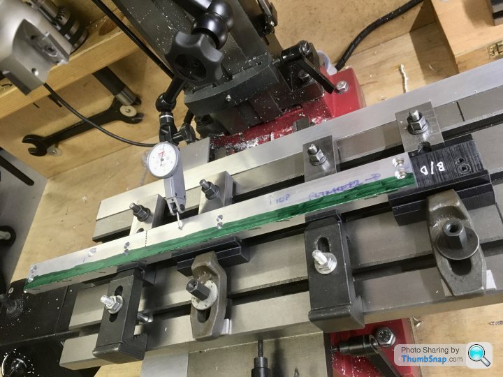
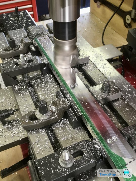
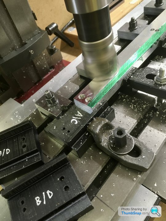
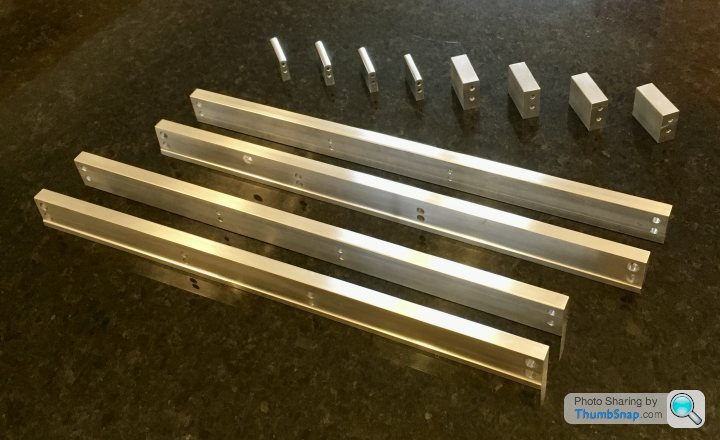
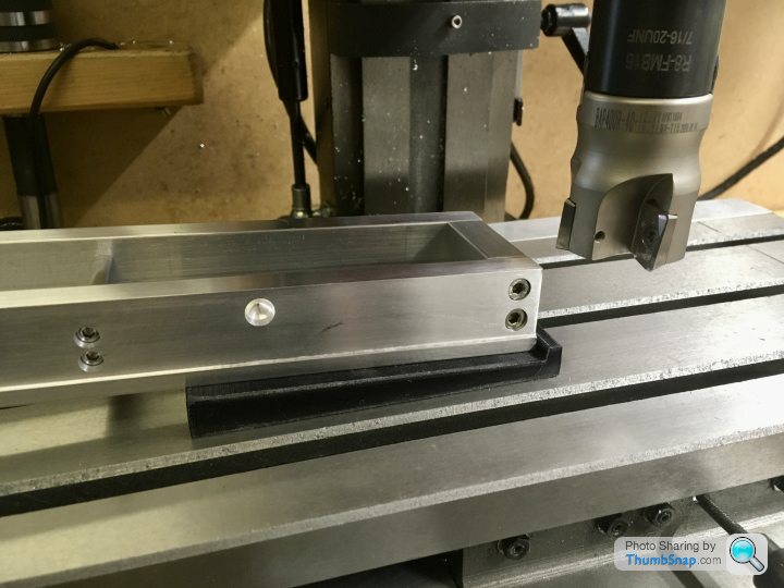
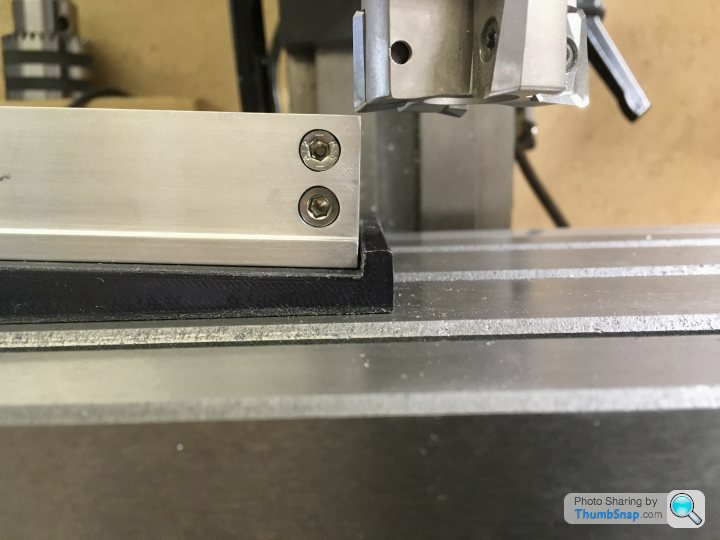
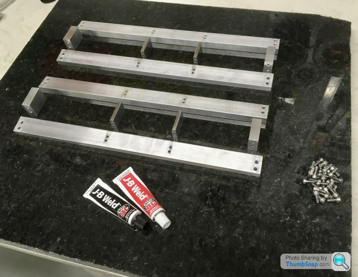
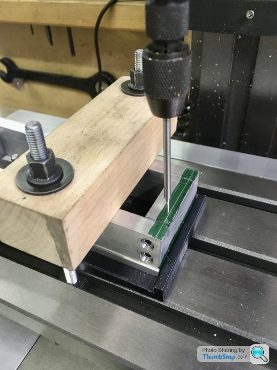
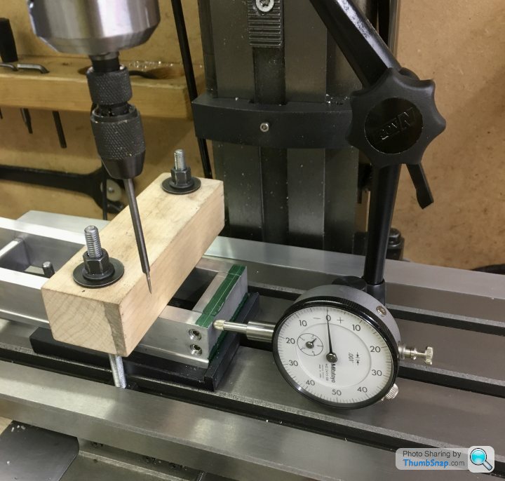
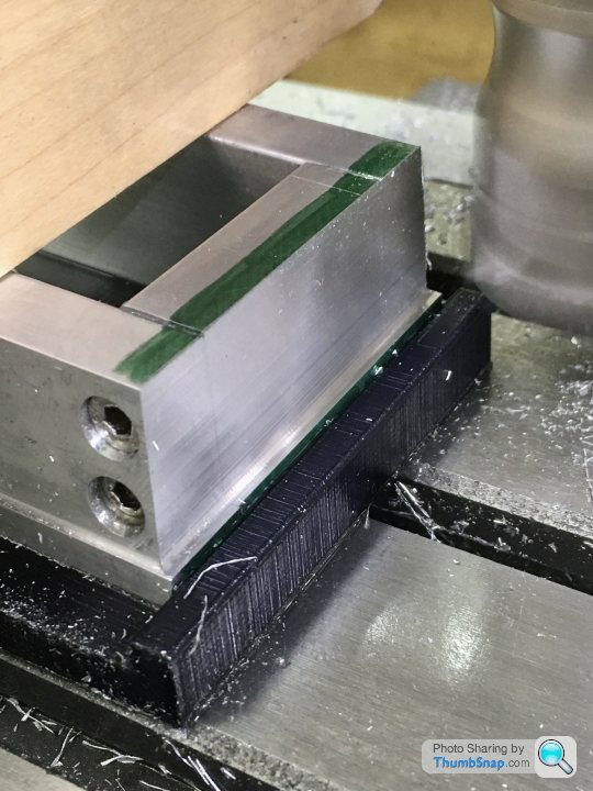
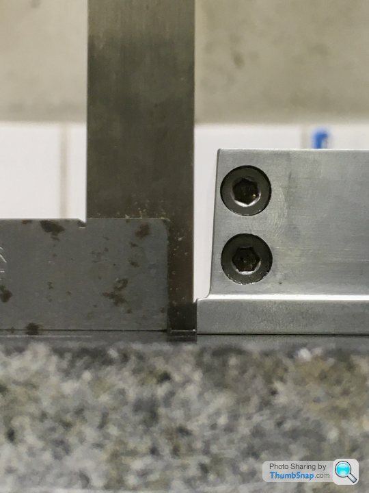
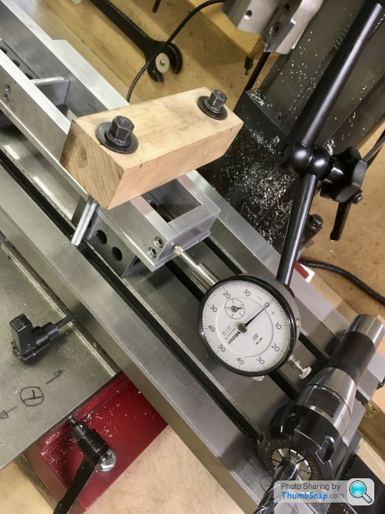
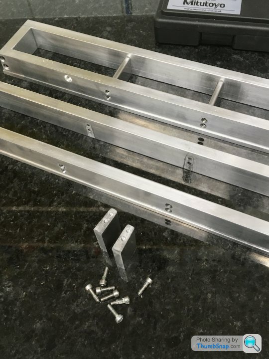
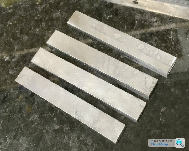
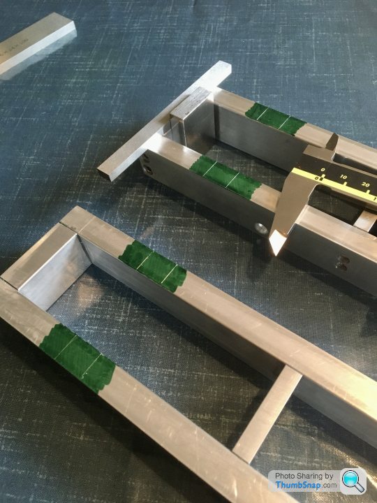
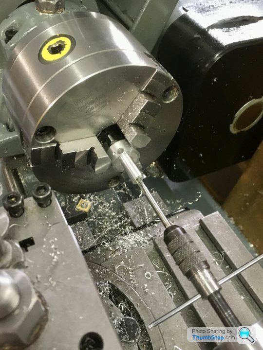
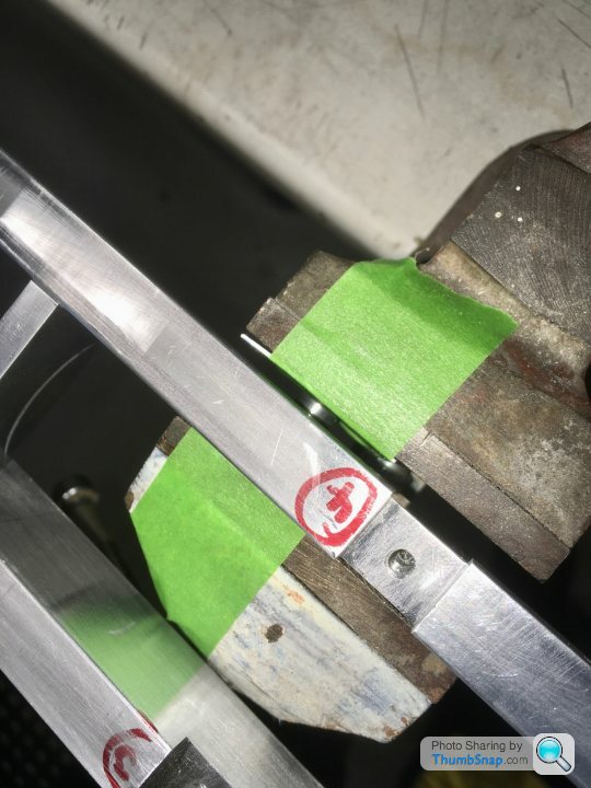
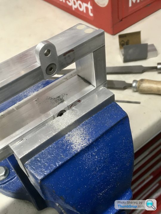
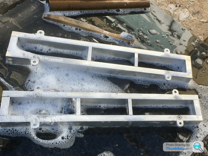
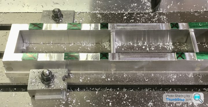
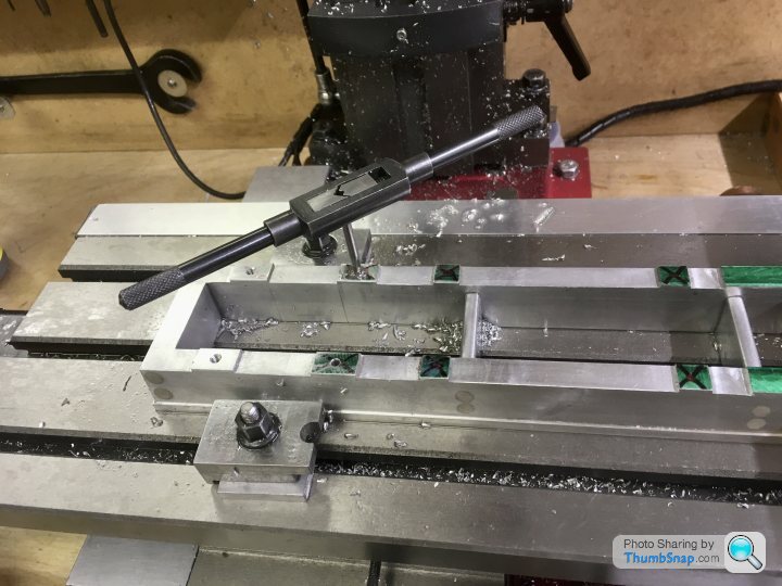
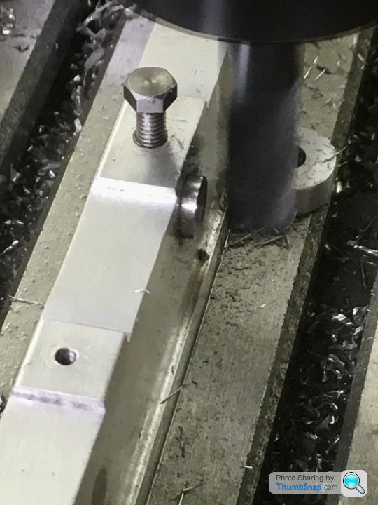
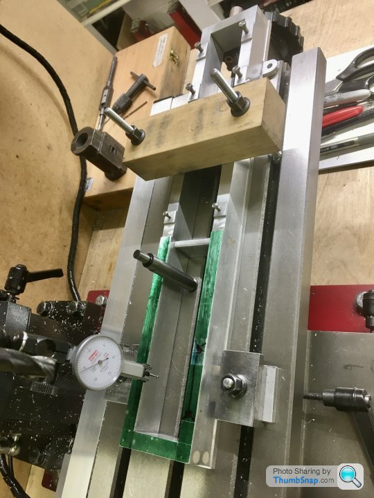
 1602 forum posts | Finally got around to using the 3D printed taper jigs today. Set up parallel with the bed, and checked both workpiece positions (they are too long to do in one pass): |
| Dr_GMJN | 15/05/2021 17:04:36 |
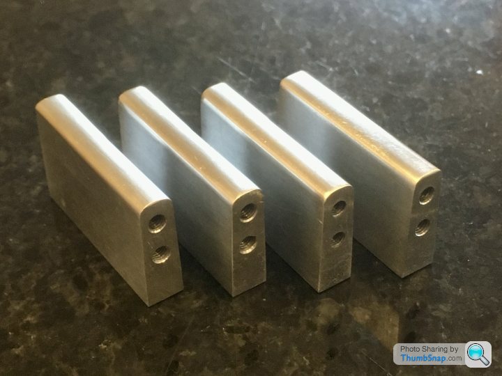
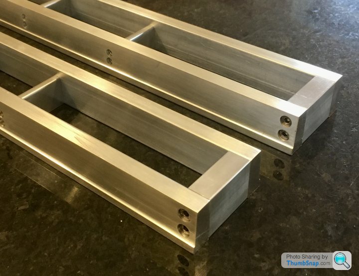
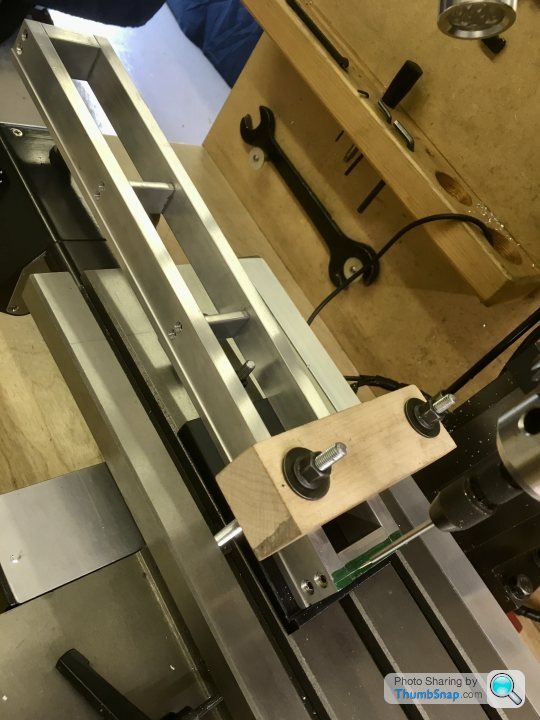
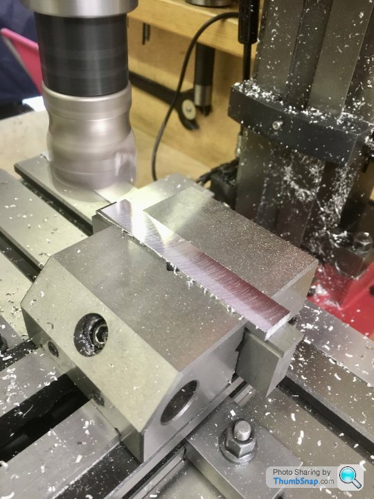
1602 forum posts | A few questions: 1) The beds are slightly warped when tightened. I'd estimate perhaps 0.010" at a corner when the opposite corner is pushed down on a level surface. If I assemble with JB Weld on the cross-piece faces, then weight the sides down while nipping the screws up, presumably when the JB Weld has set, I can fully tighten the bolts (with Loctite retainer, and hopefully they would remain true, ready for the upper surface pads to be machined? Any thoughts on this? Obviously if I can get away without skimming the lower surfaces, all the better because each one will need two setups to cover the length. 2) The end faces now need machining with their tapers. I think I'll use a spare 3 degree printed wedge for this: The idea is to traverse the shell mill side to side, and feed down in increments. I'm not sure from the insert drawing whether it's designed to do this - i.e. with a 90 degree side faces. When I've tried it before on a test piece I seem to end up with scalloped face, as if the insert sides are tapered. Any advice on this? Is it a matter of just incrementing in tiny amounts and flatting the resulting ridges? 3) Finally - the radiused internal corners. I know previous advice was to use JB Weld with a thickener. Having now used JB Weld, and finding it's a bit messy, is there any disadvantage to using white Milliput? I'm comfortable using it from plastic modelling experience, and I think I can sculpt it quite easily into radii with some basic tools and a damp cloth. Is Milliput robust enough for this application? Thanks! |
| JasonB | 15/05/2021 19:34:02 |
 25215 forum posts 3105 photos 1 articles | It should work the way you describe as just gently weighting/clamping the parts will mean the JBW fills a very fine tapered gap and the screws will just keep everything in place. On the Victoria I did recently the base was twisted on the underside and bowed up in the middle of the top so had to shim with feeler gauges and then skim the bottom flat then remachine the top. I've found the same whan machining a vertical face with teh insert cutters, you may be better off just using a 10 or 12mm cutter with 5mm high passes followed by a very shallow full height pass. Either stop 1mm high and us ethe insert cutter to form teh 0.8mm fillet or just cut right down and do the fillets at the end with filler. I use Milliput quite a bit for internal fillets as it's easy to shape with a ball ended tool and wet paintbrush and there is almost no sanding. If you do go with JBW you may find it slumping to the bottom of all the vertical corners if you do plus there is then the filing and sanding to do a thickener or letting it sit for a while after mixing should see it stay where you put it. Car body filler is another alternative, better adhesion than Milliput and easier to sand than JBW, Couple of items filleted with Superfine white.
Edited By JasonB on 15/05/2021 19:47:53 |
| Dr_GMJN | 15/05/2021 20:21:06 |
1602 forum posts | Ok thanks Jason. I’ll use Milliput for the fillets. I suppose the trick with JB Weld on the joints is to keep it off the screw threads so I can nip them up. I wonder if coating in Vaseline would do? I suppose no threadlock will be needed, since the counterbores will be full of JB Weld / Milliput eventually. Then again I could sequentially remove the screws after curing, then remove-fit with retainer? What ball tool do you use for smoothing? Ball bearing stuck to a stick or something? Ill try a 10mm end mill, and finish with the shell mill to get the same radius. |
| JasonB | 15/05/2021 20:43:28 |
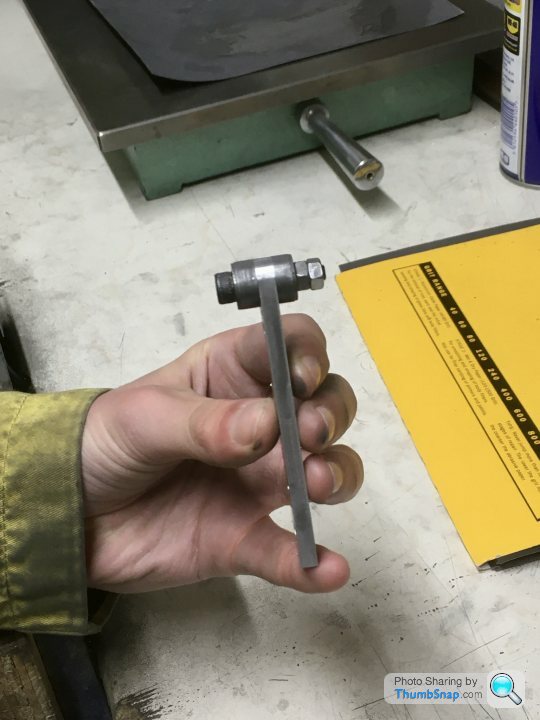
25215 forum posts 3105 photos 1 articles | You can stick a ball onto the end of a suitable handle or just round over the end of a rod. I tend to use these which are from my figure modeling days. Top one is used to apply a run of Milliput then dip the ball in water and draw along the corner. With luck you will get a nice fillet and two strips of waste material which are easily picked off and put back onto the pile. Wet artists paintbrush for a final clean up.
Yes some sort of release agent will allow then to be used to line things up but still turned when you need to tighten. I'm not keen on Milliput for filling over screw heads, usually opt for body filler, U-POL Easy was nice but now hard to get in smaller tins so have gone over to U-POL rapid but it lives up to it's name and is also a bit runnier so watch out. |
| Dr_GMJN | 16/05/2021 18:45:23 |
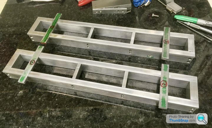
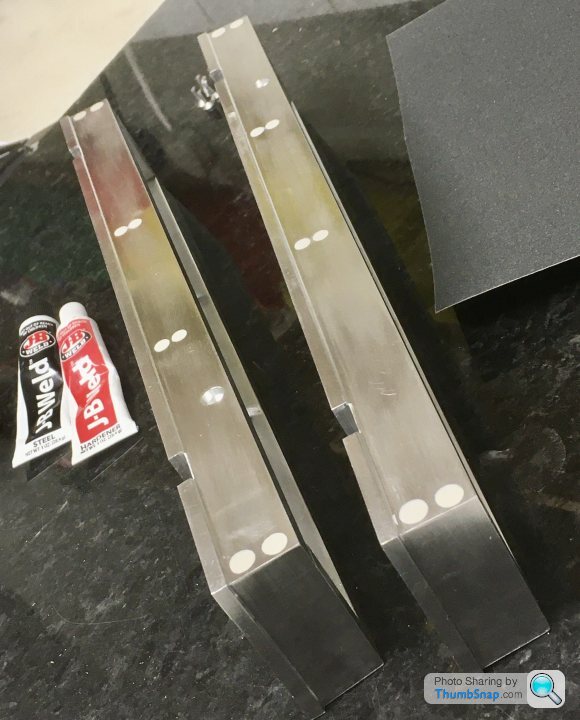
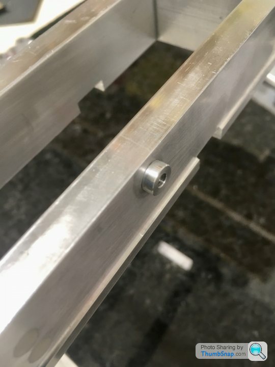
1602 forum posts | Thanks Jason - I'll get a set of those FWIW, they only seem to be a few quid off Amazon. Assembled the beds with JB Weld on the mating faces as a liquid shim. At present everything is snug tight and lightly weighted down on a flat surface. Coated the screws in Vaseline, so hopefully once everything is set true and level I can remove each screw, and fully tighten with retainer: |
| Dr_GMJN | 18/05/2021 21:59:05 |
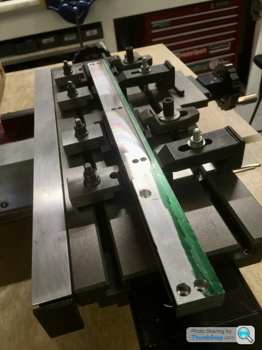
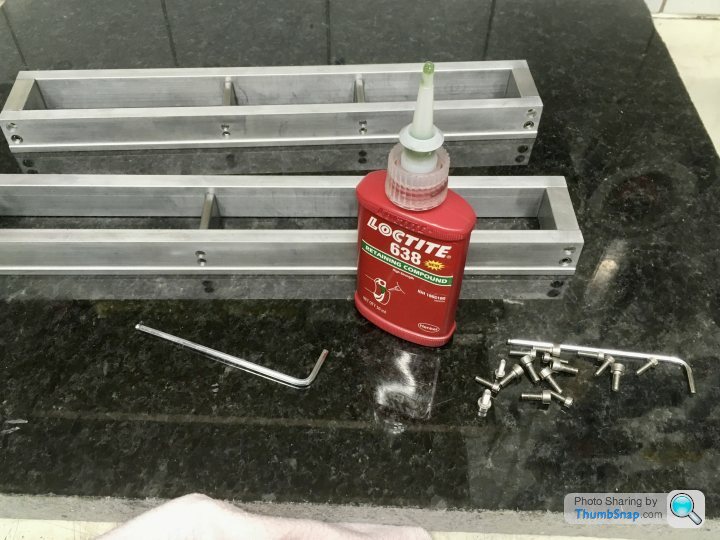
1602 forum posts | I got home earlier than expected today, so I spent a couple more hours on the beds. First off, remove and clean the screws, and replace with some retainer added: |
| Dr_GMJN | 19/05/2021 21:45:54 |
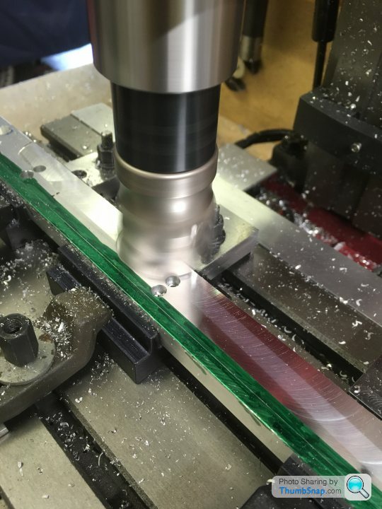
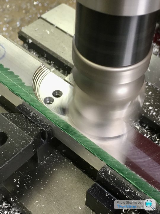
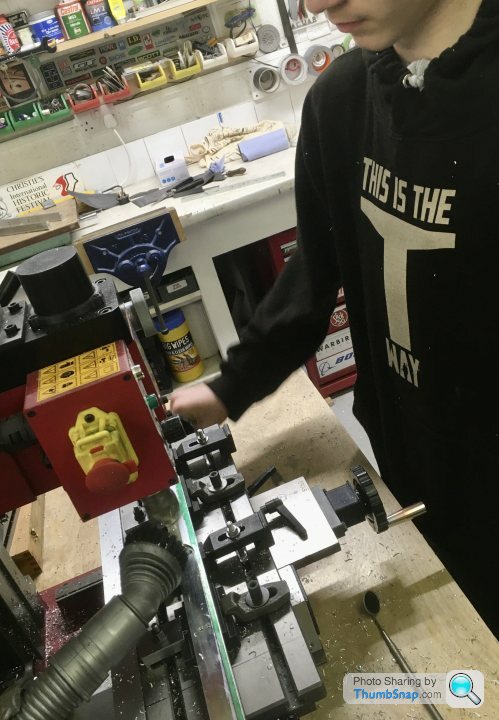
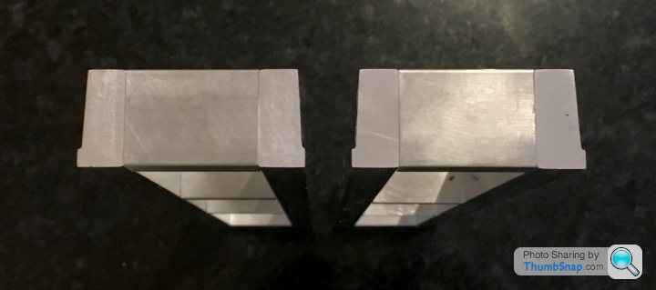
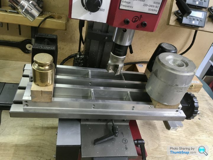
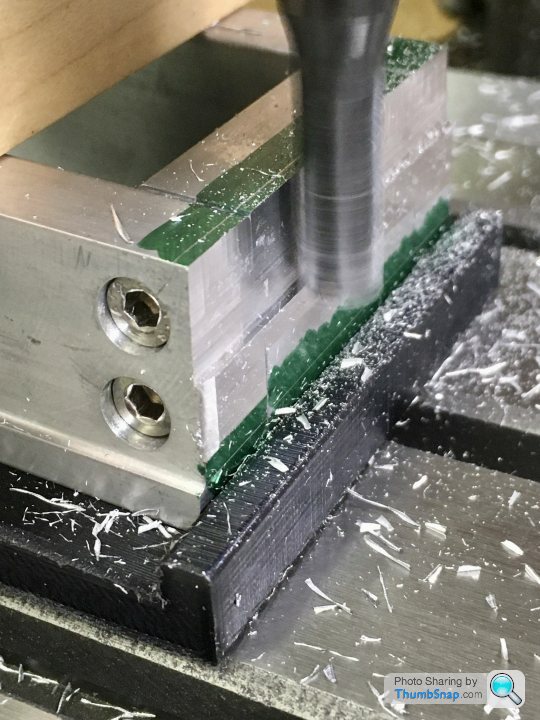
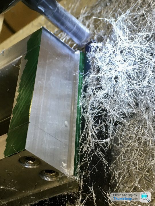
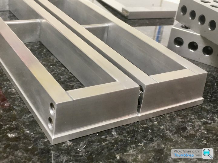
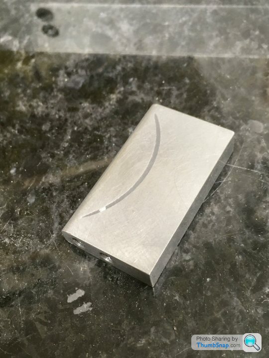
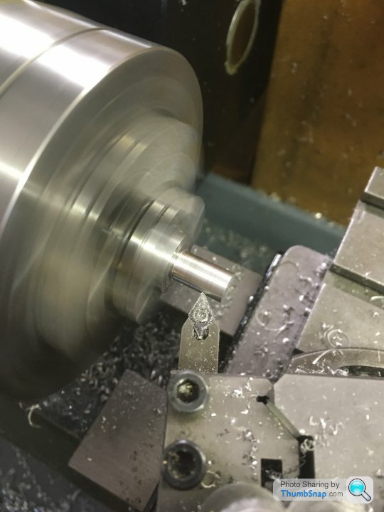
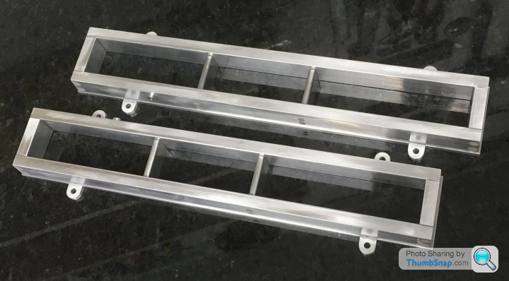
1602 forum posts | Continued with the remaining three end tapers this evening: |
| JasonB | 20/05/2021 07:00:22 |
25215 forum posts 3105 photos 1 articles | You could enlarge the holes in the side plates slightly and just tilt the cross pieces. You probably had some vaseline left in the holes which may have stopped the Loctite bonding. |
| Dr_GMJN | 20/05/2021 09:29:27 |
1602 forum posts | Posted by JasonB on 20/05/2021 07:00:22:
You could enlarge the holes in the side plates slightly and just tilt the cross pieces. You probably had some vaseline left in the holes which may have stopped the Loctite bonding. I thought about enlarging the holes, but the counterbore diameters are a very close fit on the heads, so they'd have to be milled to a slight slot. The tops of the cross pieces are kind of flat in the middle too, so they'd also need correcting, and tilting them would give a gap at one side at the base. I think overall it'll be quicker to make two new pieces, but be extra careful with orienting them on the wedges. It's very easy to get mixed up and confused with the sequence of machining to get equal angles each side. At least it is for me. Pure luck that both on the other bed were fine I suppose. Re. the Loctite, I did thoroughly clean the holes with brake cleaner aerosol, and washed the screws, but I guess not enough. It wasn't like they were loose, but just didn't take much torque to undo them. I'll use araldite next time, and also the body filler should prevent them from loosening (not that they would). |
| Dr_GMJN | 21/05/2021 16:56:55 |
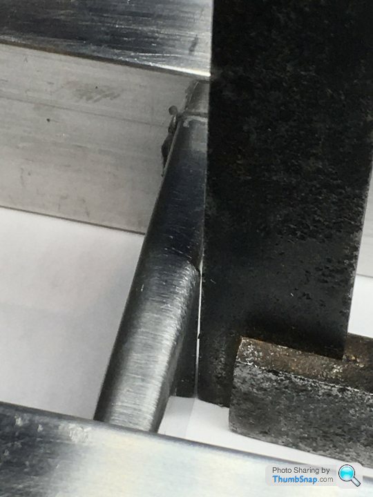
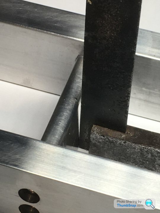
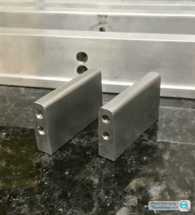
1602 forum posts | Re-made the two spacers. I know what went wrong, I think I got mixed up when swapping them on the 1.5/3 degree jigs, and ended up cancelling the taper on one side and doubling it on the other... |
| Dr_GMJN | 23/05/2021 19:54:37 |
1602 forum posts | So this is taking a lot longer than anticipated, but I’m wary of cutting corners. The whole thing sits on these beds so they have to be right despite looking pretty simple. |
| Dr_GMJN | 23/05/2021 22:34:02 |
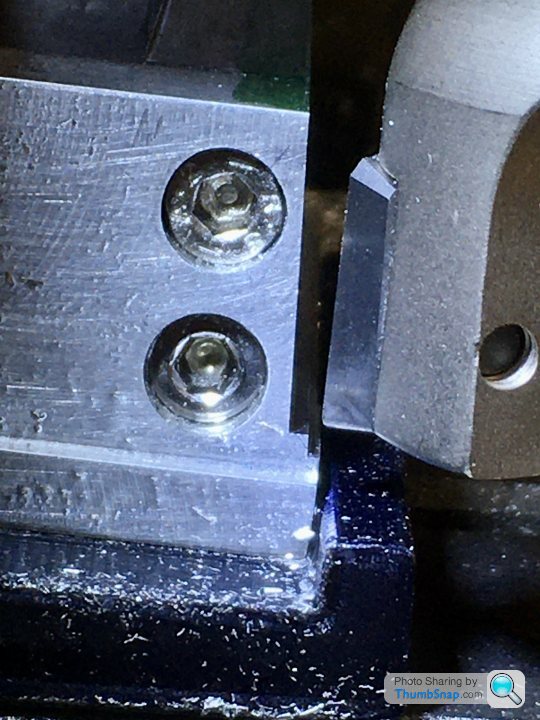
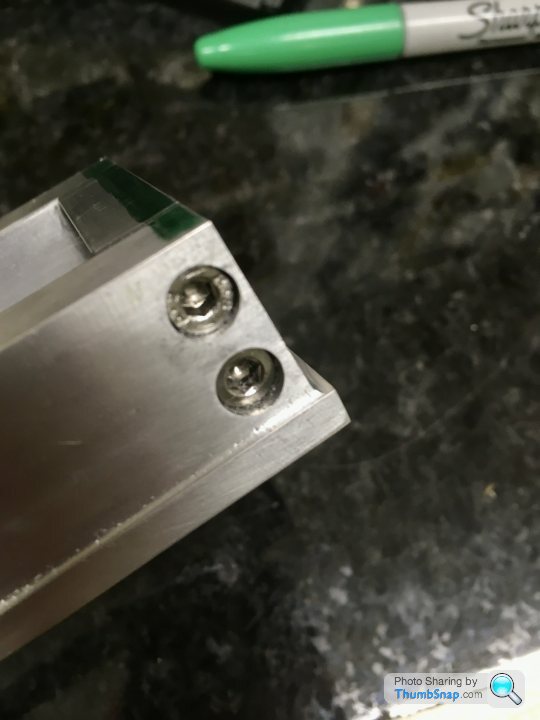
1602 forum posts | Filled the counterbores with body filler and flatted back. They’ll probably need a bit more work before they’re invisible under a coat of paint: |
| Dr_GMJN | 25/05/2021 12:08:40 |
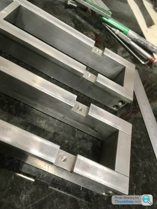
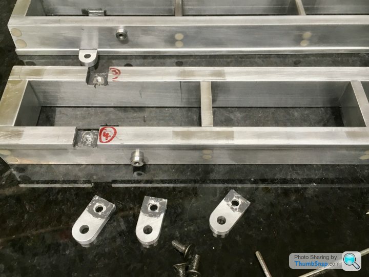
1602 forum posts | Fitted the lugs , they are a press-fit into their recesses, plus I applied some JB Weld to fill any residual gaps. The excess material on the inner faces will be filed and flatted back: Question: When I'm machining the top surfaces to leave the cylinder, crosshead mount and main bearing pads, should I drill and tap the mounting holes as well? I want them to be in the centre of the pads, so I guess while the beds are clamped accurately to the mill table, it would be OK to do them at that stage? Only slight doubt is the cylinder feet holes, which will be positioned as set on JB Weld, and secured with a bolt. I wonder if I could somehow use the bed pads themselves as a jig for when I fix the cylinder to the feet? That would guarantee the feet are in the right position. My thinking is this would be done before any cylinder machining, ie the feet would have their bases machined and the mount holes drilled, then once set and bolted, the feet would be the datum for cylinder boring, and facing. Or am I over-thinking this? Just seemed a good way of guaranteeing the cylinder and feet would be a perfect fit, and would also provide the first datum for boring. Thanks.
|
| JasonB | 25/05/2021 12:59:48 |
25215 forum posts 3105 photos 1 articles | Can't see any reason why not to do it as you describe |
| Dr_GMJN | 25/05/2021 21:25:45 |
1602 forum posts | Posted by JasonB on 25/05/2021 12:59:48:
Can't see any reason why not to do it as you describe Ok I’ll see how it goes... This evening I filed off the excess lug material: |
| Dr_GMJN | 25/05/2021 21:36:05 |
1602 forum posts | Quick question regarding the attachment screws for the feet to cylinder: If I deliberately drill all the way through the foot and the cylinder, and then use screws that protrude into the cylinder (JB Welded in place), could I then file the excess screw length off and machine the cylinder as normal? I think I’ll end up breaking through the cylinders at some point, so might as well make it deliberate and incorporate it into the process. The only potential issue is can think of is some kind of differential expansion if run on steam. Then again if it’s just steel screws and feet, and iron cylinder, maybe its ok? |
| JasonB | 26/05/2021 06:50:18 |
25215 forum posts 3105 photos 1 articles | Should be OK |
| Dr_GMJN | 26/05/2021 22:23:35 |
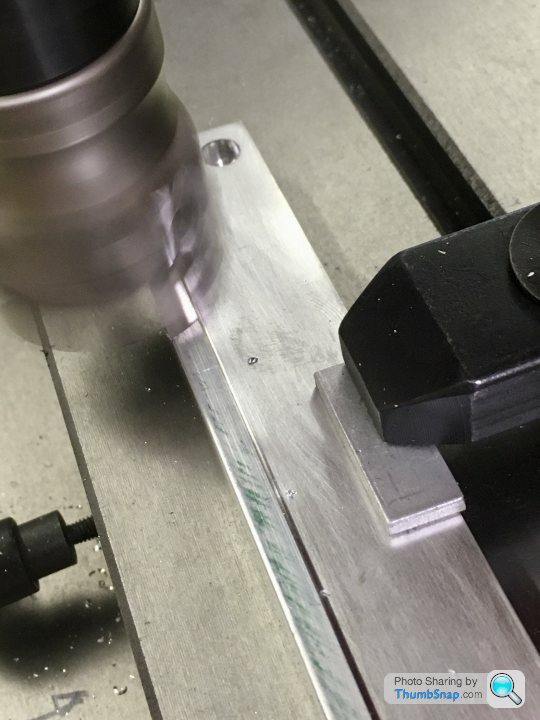
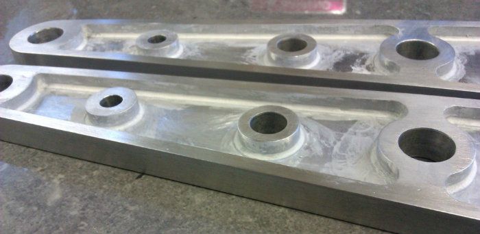
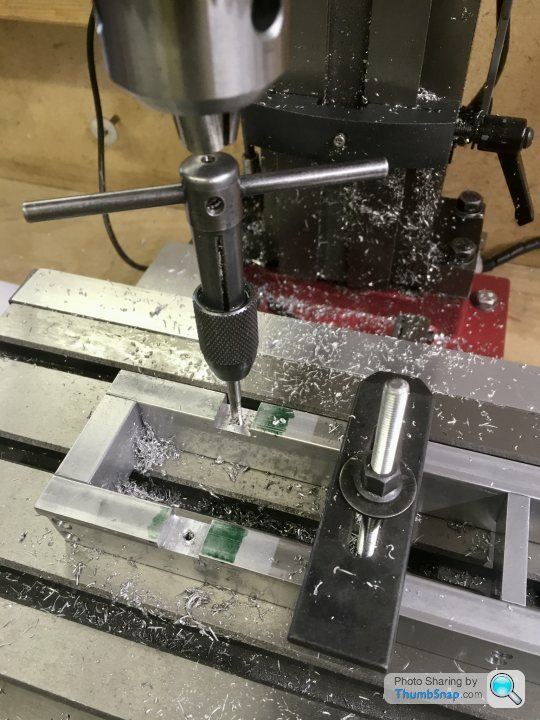
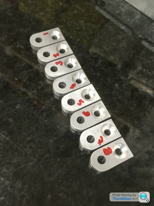
1602 forum posts | Made a start on machining the mounting pads: I hope those small threads are going to be ok in aluminium. I initially tapped the first cylinder foot hole 3BA instead of 4BA by mistake (the tap seemed tight and so luckily I didn’t get too far; I think I got away with it). I’ve made all the threads almost as deep as the bed sides to get maximum engagement. Hopefully they will be fine. |
| Dr_GMJN | 26/05/2021 22:31:37 |
1602 forum posts | So what’s a good method of matching the machined depth now Ive moved the part? I did the first half by just touching the upper surface with the tool, and incrementing down to 1.5mm. trouble is, the top surface is stock, so might be a bit wavy. I think I heard of a technique where you somehow stick some paper to the surface you want to match, then lower the tool until it moves the paper, then move the tool down by the paper thickness. Any tricks to get it perfect? Obviously I can easily blend any tiny mis-match, but it would best to avoid that. Thanks. |


![20210515_203116[1].jpg](/sites/7/images/member_albums/44290/894064.jpg "20210515_203116[1].jpg")


Please login to post a reply.
Magazine Locator
Want the latest issue of Model Engineer or Model Engineers' Workshop? Use our magazine locator links to find your nearest stockist!
Sign up to our Newsletter
Sign up to our newsletter and get a free digital issue.
You can unsubscribe at anytime. View our privacy policy at www.mortons.co.uk/privacy
Latest Forum Posts
- *Oct 2023: FORUM MIGRATION TIMELINE*
05/10/2023 07:57:11 - Making ER11 collet chuck
05/10/2023 07:56:24 - What did you do today? 2023
05/10/2023 07:25:01 - Orrery
05/10/2023 06:00:41 - Wera hand-tools
05/10/2023 05:47:07 - New member
05/10/2023 04:40:11 - Problems with external pot on at1 vfd
05/10/2023 00:06:32 - Drain plug
04/10/2023 23:36:17 - digi phase converter for 10 machines.....
04/10/2023 23:13:48 - Winter Storage Of Locomotives
04/10/2023 21:02:11 - More Latest Posts...
- View All Topics
Support Our Partners


Shopping Partners
Subscription Offer

Latest "For Sale" Ads
- Reeves** - Rebuilt Royal Scot by Martin Evans
by John Broughton
£300.00 - BRITANNIA 5" GAUGE James Perrier
by Jon Seabright 1
£2,500.00 - Drill Grinder - for restoration
by Nigel Graham 2
£0.00 - WARCO WM18 MILLING MACHINE
by Alex Chudley
£1,200.00 - MYFORD SUPER 7 LATHE
by Alex Chudley
£2,000.00 - More "For Sale" Ads...
Latest "Wanted" Ads
- D1-3 backplate
by Michael Horley
Price Not Specified - fixed steady for a Colchester bantam mark1 800
by George Jervis
Price Not Specified - lbsc pansy
by JACK SIDEBOTHAM
Price Not Specified - Pratt Burnerd multifit chuck key.
by Tim Riome
Price Not Specified - BANDSAW BLADE WELDER
by HUGH
Price Not Specified - More "Wanted" Ads...
Get In Touch!
Do you want to contact the Model Engineer and Model Engineers' Workshop team?
You can contact us by phone, mail or email about the magazines including becoming a contributor, submitting reader's letters or making queries about articles. You can also get in touch about this website, advertising or other general issues.
Click THIS LINK for full contact details.
For subscription issues please see THIS LINK.
Digital Back Issues


Donate

 Register
 Log-in
Model Engineer Magazine
- Percival Marshall
- M.E. History
- LittleLEC
- M.E. Clock

ME Workshop
- An Adcock
- & Shipley
- Horizontal
- Mill

Subscribe Now
- Great savings
- Delivered to your door

Pre-order your copy!
- Delivered to your doorstep!
- Free UK delivery!
All Forum Topics > Work In Progress and completed items > Stuart Twin Victoria (Princess Royal) Mill Engine