Forum sponsored by:

Rina and T&K drawings
| Jim Greethead | 26/03/2012 00:35:28 |
 131 forum posts 8 photos | I agree that they look slightly too large for Rina. I have obtained some glass insulin containers from a diabetic friend and they are 10.89 diameter which (at least in the simple form of oiler) look about right on the GA. I can send some to you if you would like and if you send me a PM with your address. It is a pity you live so far off the beaten track or I could drop them around when I am in London in May. I will upload an Alibre GA (with a bit of luck) showing the simple oiler and the grease caps that I intend to use on the main bearings. BTW I like the look of that sunshine in the background to your photo. Keep up the good work. It is slowly getting colder here in the mornings (8-22 today) and it will only get worse. Jim
|
| Norman Vant | 26/03/2012 01:35:20 |
| 50 forum posts 6 photos | Jim, Off the beaten track??!!?? Australia's off the beaten track! Thanks for the offer of some tubing but I've got some around that size though when I started drawing, it all looked a little... er... tight. So I went for the larger knowing I'd have to offset them. To be honest, for the amount of running it's likely to get, they're more jewelry than anything else. Worth doing though. Looking at that drawing in the album, I really should have loaded it a higher resolution. I'll have to attend to that. Regards, Norman |
| Norman Vant | 03/04/2012 16:18:26 |
| 50 forum posts 6 photos | Hello again, Back to the Rina. Thinking about the fuel system, my instinct is to have the tank at "ground level". Visually far better but it would allow the fuel to syphon back. Not really sure how effective and reliable an unsprung check valve would be. Put in a spring and one can't be sure that the suck would be sufficient to overcome it. My next thought is to mount the carb at tank level and have an intake manifold from there. A remote carb seems to work on model aero 4-strokes and they are looking for performance - I'm not. The other alternative is to go with the Jan Ridders vapouriser. It just seems a tad complicated for such a low performance engine. Any thoughts would be appreciated, especially from anyone who has completed a Rina or any other petrol hit and miss for that matter. Regards, Norman. |
| JasonB | 03/04/2012 16:45:22 |
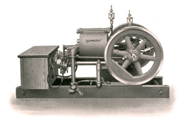
 25215 forum posts 3105 photos 1 articles | On the horizontals that I have done and also the Domesrtic I'm working on now the fuel tank has been in the engines base casting so just below carb level and I've not had problems with starvation and like you say better to run back slightly than flood the carb, you can see the relation between carb & tank the Zero six I suppose if you do get a bit of starvation you could do as the IC glow engines and pressurise the tank from the exhaust. The ideal is to have the tank below and use a fuel pump, constant level chamber in the carb and a gravity return for excess fuel like the IHC particularly with vertical engines as the intake is at the top of the engine. J |
| Jim Greethead | 03/04/2012 21:53:18 |
131 forum posts 8 photos | I used a Ridders Vaporiser on my Bonza engine and it worked fine - and dead simple to make. And then it stopped working for reasons not known to this officer. So I built the carb that was specified in the magazine - just a simple venturi with needle valve. But it had an unsprung ball valve to prevent fuel running back to the tank (which is mounted below carb level) and that worked fine. My intention is to use a Vaporiser on my Rina when I get back to it despite having made the gas carby because I still can't figure out how to connect the gas carby to a gas source ( but that's another story). In short, I have tried both, and both work. Take your pick. And let us know the outcome. Jim
|
| Norman Vant | 10/08/2012 14:05:30 |
| 50 forum posts 6 photos | Hello again, Back at last! Work and an unruly garden have impeded progress on the Rina greatly. However, some advances have been made and the beasty is ready (at leat mechanically) for a test run - not painted or properly mounted - but ready to try. I still think I need some advice from the sparks gurus, though. I have sourced some ignition components and the points are fitted to the engine. Unfortunately, there is no room there for the condenser. I am assuming that it amounts to the same thing if I connect said condenser across the coil LT terminals on the coil (they are only at the other end of the wires, after all!?!). If I can manage to add the pictures to this post you will see my attempt to test the system "in hand" so to speak. The coil is off a small Honda bike and the lugs either side are what I assume to be the mountings and earth terminal combined, since there is only one LT wire. These lugs are sort of laminated metal. Is my assumption about them being the earth correct? The white battery box contains 4 x AA Duracels.
The reason for my doubts is that I only seem to get a rather weak spark at the plug and a much brighter one at the +ve terminal when I break the circuit by hand. That doesn't sound good. I'd like to get this sorted out off the motor so that I will know that it's one less reason for the thing not to run. I anyone can confirm that this set-up is correct -or tell me why it's no, I'd be very grateful. P.S. Jim, did you enjoy your trip to the UK and our apalling weather? Regards,
Norman |
| Norman Vant | 10/08/2012 14:12:12 |
| 50 forum posts 6 photos | Just a little query, Does anyone know how to stop the vertical advertising banner obscuring the text on the right of the screen? Regards, Norman.
|
| JasonB | 10/08/2012 15:48:11 |
25215 forum posts 3105 photos 1 articles | The central bar is a common negative of both the primary and secondary coils, as the chassis of teh bike/car would be negative grouind you can say its the earth. You may also find my recent Buzz coil thread of use.
J |
| Jeff Dayman | 10/08/2012 16:15:09 |
| 2356 forum posts 47 photos | Hi Norman, Good to hear from you again. A few comments re your setup in the pics. 1. The 4 AA batteries may not have enough current to operate it. I would start with a power supply able to supply at least 1 amp. Last year we discussed using wall wart power supplies with at least 1 amp rating at 12 VDC. 2. The plug wire and cap look like the suppressor type which have high internal resistance.The wire may also be a resistor type. Both these items will increase the need for higher drive current. If you can, substitute copper core plug wire, plain metal plug cap terminal and a non resistor plug (ie like a Champion CJ-8 for example) and try the circuit again. Before attempting to remove the plug wire from the coil, pull back the rubber boot and look for mould flash or sealant around the wire. If there is none, chances are the wire is screwed in onto a terminal which is just like a wood screw, down in the coil socket. The screw is intended to make contact with the plug wire core. At least that was the way these coild used to be connected to the wires. Some however used sealant or were moulded in place and these wires can not be removed without damaging the coil, so use caution. As I said if there is no mould flash or sealant, the wire can probably be screwed out easily. Before altering anything though I would try driving the circuit as-is with more current. Good luck JD
|
| jason udall | 10/08/2012 17:21:26 |
| 2032 forum posts 41 photos | Err. whats completing the "earth" between the chassy connection of the coil and the plug? I know the engin will in normal use but in the photos above ???... Just a thought.
|
| jason udall | 10/08/2012 17:25:33 |
| 2032 forum posts 41 photos |
Oh and the AA batteries if ALKALINE might suprise you as to how low their internal resistance is .. so 1 amp might be possible....but maybe not for long. |
| JasonB | 10/08/2012 17:29:41 |
25215 forum posts 3105 photos 1 articles | Jason I suspect the black wire is being touched against the plug body to test the circuit.
J |
| jason udall | 10/08/2012 17:39:11 |
| 2032 forum posts 41 photos | Batteries might do 1 amp but have douts over battery box ....
|
| Jim Greethead | 10/08/2012 21:54:57 |
131 forum posts 8 photos | Hi Norman, It is good to see you back again and to know that you are close to having a working engine. I agree with the other posts: the wires from the battery box look a bit skinny for the current required and you do need an earth return from the plug to the earth on the coil. The coil is probably designed to work off 12 volts so connecting the setup to your car battery should produce a healthy spark. Then you could compare that spark with the one from the 6 volt battery box. The weather in May? Glasgow and Edinburgh were freezing, as was our visit to The Shuttleworth Collection. But the last few days in London were 27 degrees; wonderful and a nice memory to speed us on our way. Harrogate was a revelation. Bigger, better and brighter than anything I have seen before. And I met some of the Madmodders as well. It was a good day. Pity is is so far away. Jim PS I am hanging out for photos of the finished article
|
| Norman Vant | 11/08/2012 14:56:01 |
| 50 forum posts 6 photos | Thanks for the responsed. To clarify a pew points about my quick and dirty set-up: the plug lead is copper - a bit of a surprise in this day and age. The plug is a CM6 which seems to be recommended for this type of engine and others have success with them. Anyway, the rather unusual 10mm thread is already cut in the head, so I'm stuck with it. The plug cap is the one supplied with it and similarly is recommended elsewhere. To test, using all three hands, the plug body was held against the mounting lug on the coil and the black wire from the battery pack was used to make and break the contact, again to the coil's mounting lug. I certainly got a spark at the electrodes but not as fat as I would have liked. I was assured that the coil was 6V when I bought it - but who knows? The thing I was unsure about was whether the condenser was connected to the right things and in the correct orientation. I can't fit it at the points for lack of space. Worryingly, I was getting a far bigger LT spark, on make and break, than the HT one. Like most people, I have drawers full of mains chargers for various, long-forgotten, appliances. However, not one of them is rated above 7.5 V and 150mA. So, not much help there. I may have to use jump leads from the lawnmower, which has a 12V battery and shares the workshop! What is exercising my mind, looking forward a bit, is the I would like the whole thing to be self-sufficient as a unit (within battery capacity) and a 12V lead/acid battery is going to be completely out of scale and impossible to conceal without mounting the engine on a disproportionately large box, rather than the skid that I had planned. What on earth do other people do? I had a look a the buzz-coil thread. Loads of references to these on the internet but all written in terms that make my eyes glaze over. Now, about that advertising banner on the right.....
Regards, Norman.
|
| JasonB | 11/08/2012 16:29:26 |
25215 forum posts 3105 photos 1 articles | Norman, I intend to fit my whole buzz coil and battery into a small wooden case as well, something like this. I bought a 6V lead acid battery that measures 98x25mm and 52mm high, there are plenty of them on the net and with a charger come in about £15.00. The Minimag man also sells them. If you felt the need for 12V then two could be fitted in series and as they are sealed they can be laid on their side to keep the height down J Edited By JasonB on 11/08/2012 16:30:49 Edited By JasonB on 11/08/2012 16:32:24 |
| Norman Vant | 12/08/2012 13:21:06 |
| 50 forum posts 6 photos | Jason,
Well, that's that ordered! Should have bought their coil really but it's fiendishly expensive for what it is. Can you confirm that it's OK to fit the condenser anywhere in the LT circuit between the +ve and ground? I'm out of my comfort zone here.
Regards, Norman. |
| Norman Vant | 12/08/2012 13:55:17 |
| 50 forum posts 6 photos | Jason, I've just had another go with the setup "in hand" using jump leads from a 12V lead/acid battery. Something is seriously wrong! -ve clip on the mounting lug. Yellow+ve feed touched against the +ve croc clip. With the plug held against the earth lug, on breaking the circuit I'm not getting a spark at the plug, I do get a jolt that I can detect with my fingers but not enough to make me jump about. I'm getting a truly massive LT spark from the contact I'm breaking and the earth lugs are getting too hot to touch. I'm no electrics expert but I have wired a car, from scratch, with no problems (just a headache) and I never came across this sort of thing . The coil was new and unused from a motorcycle electrics dealer so I have to assume that it is in working condition but what's going on!!!???!!! Don't really waht to spend £50-odd (with VAT and postage) for a purpose-made one. Help! Norman. . |
| JasonB | 12/08/2012 16:30:04 |
25215 forum posts 3105 photos 1 articles | I would go +ve battery terminal to +ve primary , thats the tab on the coil. center bar of coil to wire of capacitor and to one side of points Ground capacitor body and other side of points -ve of battery to ground |
| Ian Richards 3 | 12/08/2012 19:43:27 |
| 5 forum posts | After about a year (and a lot of references to this thread), my Rina almost spluttered into life today! I've 95% followed the design published in the magazine, with the clarifications and improvements published on here. I've deviated from the published design with the ignition system though - I've put a cam on the crankshaft (inside the 'back' flywheel), which drives the contact breaker from a mini and seems to work well with a test spark plug. This gives a wasted spark (at the end of the exhaust stroke), but I can't see a problem with this. On butane (regulated down to 28 mbar), the engine fires fairly reliably, although the adjustment of the needle valve is very critical. It doesn't seem to generate much power though, and only runs for between 10 & 30 seconds before running out of steam.... My suspicion is that my valves aren't sealing as well as they should. When I turn the engine over by hand you get a certain amount of 'bounce' as the air is compressed', but if you do the compression stroke over about 5 seconds, it's apparent that all the pressure has leaked out. How does this match with anyone else's experiennce? If you put a lit candle next to the exhaust port, you occasionally also get a puff of flame from the exhaust on the compression stroke when you turn the engine over at about 200 RPM. Any advice as to whether this leakage is significant would be appreciated.
Thanks Ian
|


Please login to post a reply.
Magazine Locator
Want the latest issue of Model Engineer or Model Engineers' Workshop? Use our magazine locator links to find your nearest stockist!
Sign up to our Newsletter
Sign up to our newsletter and get a free digital issue.
You can unsubscribe at anytime. View our privacy policy at www.mortons.co.uk/privacy
Latest Forum Posts
- hemingway ball turner
04/07/2025 14:40:26 - *Oct 2023: FORUM MIGRATION TIMELINE*
05/10/2023 07:57:11 - Making ER11 collet chuck
05/10/2023 07:56:24 - What did you do today? 2023
05/10/2023 07:25:01 - Orrery
05/10/2023 06:00:41 - Wera hand-tools
05/10/2023 05:47:07 - New member
05/10/2023 04:40:11 - Problems with external pot on at1 vfd
05/10/2023 00:06:32 - Drain plug
04/10/2023 23:36:17 - digi phase converter for 10 machines.....
04/10/2023 23:13:48 - More Latest Posts...
- View All Topics
Support Our Partners


Shopping Partners
Subscription Offer

Latest "For Sale" Ads
- Reeves** - Rebuilt Royal Scot by Martin Evans
by John Broughton
£300.00 - BRITANNIA 5" GAUGE James Perrier
by Jon Seabright 1
£2,500.00 - Drill Grinder - for restoration
by Nigel Graham 2
£0.00 - WARCO WM18 MILLING MACHINE
by Alex Chudley
£1,200.00 - MYFORD SUPER 7 LATHE
by Alex Chudley
£2,000.00 - More "For Sale" Ads...
Latest "Wanted" Ads
- D1-3 backplate
by Michael Horley
Price Not Specified - fixed steady for a Colchester bantam mark1 800
by George Jervis
Price Not Specified - lbsc pansy
by JACK SIDEBOTHAM
Price Not Specified - Pratt Burnerd multifit chuck key.
by Tim Riome
Price Not Specified - BANDSAW BLADE WELDER
by HUGH
Price Not Specified - More "Wanted" Ads...
Get In Touch!
Do you want to contact the Model Engineer and Model Engineers' Workshop team?
You can contact us by phone, mail or email about the magazines including becoming a contributor, submitting reader's letters or making queries about articles. You can also get in touch about this website, advertising or other general issues.
Click THIS LINK for full contact details.
For subscription issues please see THIS LINK.
Digital Back Issues


Donate

 Register
 Log-in
Model Engineer Magazine
- Percival Marshall
- M.E. History
- LittleLEC
- M.E. Clock

ME Workshop
- An Adcock
- & Shipley
- Horizontal
- Mill

Subscribe Now
- Great savings
- Delivered to your door

Pre-order your copy!
- Delivered to your doorstep!
- Free UK delivery!
All Forum Topics > Drawing Errors and Corrections > Rina and T&K drawings