Forum sponsored by:

Jason's Firefly .46 Build
| JasonB | 24/11/2018 16:15:19 |
 25215 forum posts 3105 photos 1 articles | Ian, there are no ball races in this engine. You can ream the crank pin hole using a hand reamer and take advantage of the reamers taper so that the pin will start to enter the hole but is then pressed into an ever tightening tapered hole which helps keep it lined up |
| Ian Hewson | 24/11/2018 17:21:39 |
| 354 forum posts 33 photos | Hi Jason A couple of people have mentioned fitting ball races as an improvement, wondered if it is worth while? Would you have the glow plug type handy, never had any experience with model aero engines, but it seems that the glow plugs react similarly to spark plugs in a tuned car engine. Ian |
| Peter Wood 5 | 24/11/2018 18:34:44 |
| 94 forum posts 11 photos | Ian An OS # 8 would be a good starting point. I use them in most of my 2-stroke aero engines. Peter |
| JasonB | 24/11/2018 18:39:48 |
25215 forum posts 3105 photos 1 articles | Yes OS #8 was what I ran mine with. As to bearings, I suppose it depends on what you want to do with the engine. For me just the odd bench run is all it will get so the bronze ones are fine. A bit of gentle flying will also be OK with teh bronze it is only if you want to push it harder that ballraces may be worth thinking about. |
| Ian Hewson | 24/11/2018 18:50:16 |
| 354 forum posts 33 photos | Thanks Peter and Jason Solid bearing it is then, always good to have advice, just been checking my taps, gues which one I don’t have for the plug lol. |
| JasonB | 24/11/2018 19:49:34 |
25215 forum posts 3105 photos 1 articles | Make sure you get 1/4x32 UNEF not ME |
| Ian Hewson | 24/11/2018 19:52:28 |
| 354 forum posts 33 photos | Thanks Jason, just noticed the two different threads whilst looking for the best supplier. |
| Peter Wood 5 | 11/12/2018 10:58:46 |
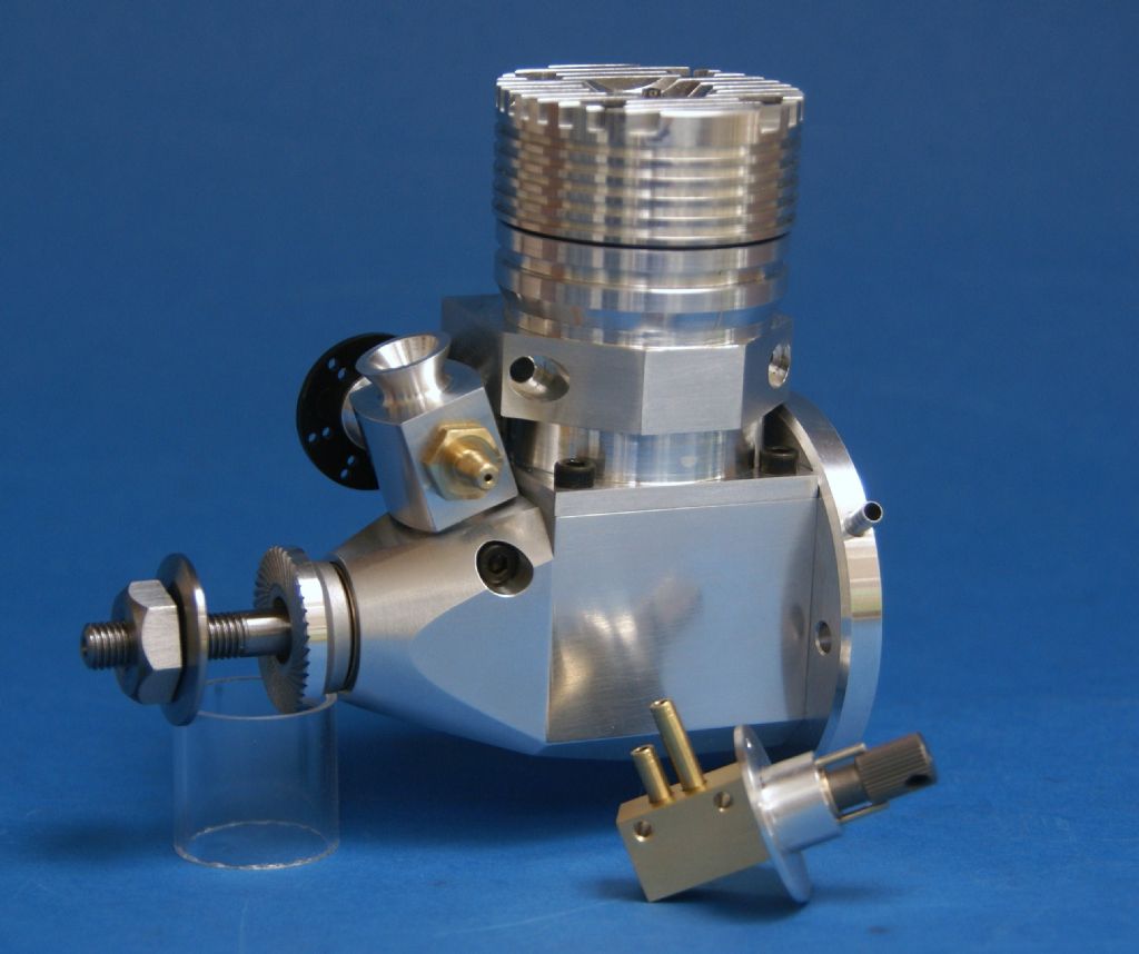
| 94 forum posts 11 photos | I am now making a second Firefly learning from the mistakes on the first and adding cooling fins to the head and beam mounting. On the first one I used a commercial prop driver but this time I want to make my own. Two questions. How do I drill a hole with a flat. Jasons excellent thread does not mention this part. Would I be better making a tapered split collet to secure the driver on the prop shaft? Secondly how do I mill the radiused grooves on the driver face? Peter |
| JasonB | 11/12/2018 12:19:02 |
25215 forum posts 3105 photos 1 articles | Peter, this came up the other day in this thread if you follow my link in that thread you will also see one simple way to do the serrated face. |
| geoff walker 1 | 11/12/2018 13:46:13 |
| 521 forum posts 217 photos | Peter, If you don't want to make a stepped broaching tool you could make a keyed driver instead. I made one for my firefly. you would of course have to mill a keyway slot in the crankshaft. If you go back to page 5 in this thread you will see the driver and crankshaft with the key fitted in my parts photograph. Geoff |
| Peter Wood 5 | 11/12/2018 17:11:10 |
| 94 forum posts 11 photos | Jason Thanks. I missed that thread. The use of a vertical knurling tool is a great idea. I have previously made prop drivers for larger engines for friends by tilting the mill head at 45 deg and just making grooves across the face but I felt this needed proper radial knurling. However not having an arbor press I am not keen on using my mill or Myford in that role. Geoff. Milling the keyway in the crankshaft is not a problem. Thinking about it I have made internal keyways as required on the prop driver by drilling the correct size hole on the joint line of the crankshaft hole and a temporary plug. Then it is just a matter of squaring the hole with careful filing. Meanwhile I am still contemplating a split tapered collet as was made in the RCME build article. Peter |
| Peter Wood 5 | 11/12/2018 18:02:32 |
| 94 forum posts 11 photos | Jason Just tried the knurling technique with an old rusty tool I had in my scrap box./Worked like a charm. Thanks Peter |
| JasonB | 11/12/2018 18:12:10 |
25215 forum posts 3105 photos 1 articles | Peter, I'm not sure about your arbor press comment, I just did mine in the bench vice with an odd 1/2" drive socket as a spacer
|
| Peter Wood 5 | 11/12/2018 18:21:25 |
| 94 forum posts 11 photos | Aaaaah. Misunderstood the picture. I thought it was vertical not horizontal. After my breakthrough with the old knurling tool i will give your broaching method a try. Thanks again. Peter |
| Ian Hewson | 05/01/2019 20:18:30 |
| 354 forum posts 33 photos | A question about the port dimensions, the cylinder block exhaust port is shown as 10.5mm x 5.5mm, whilst the cylinder liner port is shown as 15.285mm x 4.96mm. How critical are these dimension as the are shown to three places of decimals? I would have thought that the liner would have been the important dimension for the exhaust, is it to do with back pressure as in a car engine? As I mentioned before, I have not had any experience with 2 stroke engines. |
| JasonB | 05/01/2019 20:30:06 |
25215 forum posts 3105 photos 1 articles | The three decimal places of the exhaust port are more a product of the CAD package when it rolls the liner out into a flat plane, the 14.35mm is what you will actually machine. Width wise you have a bit more leway but the heights of the ports are what really set the timing of the engine so they are what you should aim to get as close as possible. The crank case hole is a little larger than the port in both directions so it does not offer any resistance to gas flow and is less critical than the liner. |
| Ian Hewson | 05/01/2019 21:00:05 |
| 354 forum posts 33 photos | Hi Jason Thanks for your prompt reply, appreciated, so the holes on the liner are the critical ones, and should not be restricted in diameter by the holes in the block when it is fitted? The 10.5mm exhaust hole was the one that was confusing me as it seems to restrict the port in the liner. Just measured the plan, and I can now see that the 14.35mm is due to the curvature of the cylinder, didn’t want to bu**er up the block on the last cut. Ian
|
| JasonB | 06/01/2019 07:03:50 |
25215 forum posts 3105 photos 1 articles | That's it liner is the one to get right particularly height. The 10.5 and 14.35 are basically one and the same dimension, if you were to project two vertical lines upwards on the drawing that shows the 14.35 the distance apart would be about 10.2 as the 45degree cut is the long edge of a 10.5 x 10.5 triangle with a bit to spare.
Edited By JasonB on 06/01/2019 07:08:57 |
| Ian Hewson | 24/01/2019 18:36:01 |
| 354 forum posts 33 photos | Another question, do you use any gaskets or sealants, for the cylinder head, engine backplate or block to cylinder? |
| JasonB | 24/01/2019 18:39:11 |
25215 forum posts 3105 photos 1 articles | I didn't but if you feel the need then a smear of a liquid gasket would be the best bet to keep backplate clearance and compression ratio the same. |


Please login to post a reply.
Magazine Locator
Want the latest issue of Model Engineer or Model Engineers' Workshop? Use our magazine locator links to find your nearest stockist!
Sign up to our Newsletter
Sign up to our newsletter and get a free digital issue.
You can unsubscribe at anytime. View our privacy policy at www.mortons.co.uk/privacy
Latest Forum Posts
- hemingway ball turner
04/07/2025 14:40:26 - *Oct 2023: FORUM MIGRATION TIMELINE*
05/10/2023 07:57:11 - Making ER11 collet chuck
05/10/2023 07:56:24 - What did you do today? 2023
05/10/2023 07:25:01 - Orrery
05/10/2023 06:00:41 - Wera hand-tools
05/10/2023 05:47:07 - New member
05/10/2023 04:40:11 - Problems with external pot on at1 vfd
05/10/2023 00:06:32 - Drain plug
04/10/2023 23:36:17 - digi phase converter for 10 machines.....
04/10/2023 23:13:48 - More Latest Posts...
- View All Topics
Support Our Partners


Shopping Partners
Subscription Offer

Latest "For Sale" Ads
- Reeves** - Rebuilt Royal Scot by Martin Evans
by John Broughton
£300.00 - BRITANNIA 5" GAUGE James Perrier
by Jon Seabright 1
£2,500.00 - Drill Grinder - for restoration
by Nigel Graham 2
£0.00 - WARCO WM18 MILLING MACHINE
by Alex Chudley
£1,200.00 - MYFORD SUPER 7 LATHE
by Alex Chudley
£2,000.00 - More "For Sale" Ads...
Latest "Wanted" Ads
- D1-3 backplate
by Michael Horley
Price Not Specified - fixed steady for a Colchester bantam mark1 800
by George Jervis
Price Not Specified - lbsc pansy
by JACK SIDEBOTHAM
Price Not Specified - Pratt Burnerd multifit chuck key.
by Tim Riome
Price Not Specified - BANDSAW BLADE WELDER
by HUGH
Price Not Specified - More "Wanted" Ads...
Get In Touch!
Do you want to contact the Model Engineer and Model Engineers' Workshop team?
You can contact us by phone, mail or email about the magazines including becoming a contributor, submitting reader's letters or making queries about articles. You can also get in touch about this website, advertising or other general issues.
Click THIS LINK for full contact details.
For subscription issues please see THIS LINK.
Digital Back Issues


Donate

 Register
 Log-in
Model Engineer Magazine
- Percival Marshall
- M.E. History
- LittleLEC
- M.E. Clock

ME Workshop
- An Adcock
- & Shipley
- Horizontal
- Mill

Subscribe Now
- Great savings
- Delivered to your door

Pre-order your copy!
- Delivered to your doorstep!
- Free UK delivery!
All Forum Topics > Work In Progress and completed items > Jason's Firefly .46 Build