Forum sponsored by:

Further Adventures with the Sieg KX3 & KX1
A thread for new owners of these machines to post in.
| Ron Laden | 12/09/2019 09:42:20 |
 2320 forum posts 452 photos | Posted by JasonB on 12/09/2019 07:53:24:
4-flute which I mostly use as the majority of the metal gets removed first with a standard cutter so you don't need 2 flutes to clear a lot of aluminium swarf and the big bonus is you can feed twice as fast as a 2-flute and still have the same chip load. I did also but a 2-flute in 6mm but have not used it yet. A bit of paraffin and some air when cutting aluminium seems to stop anything sticking to the coated end as uncoated seem a bit harder to come by. Jason, your 4 flute link goes to Model Engine Maker pages..? Looking at those 2 flute prices they are very good some of the ones I found when I had a look were £30 upwards. |
| Old School | 12/09/2019 10:22:03 |
| 426 forum posts 40 photos | I use that company for PCD inserts for turning high silicon content aluminium and parting off inserts for aluminium will try their milling cutters now. |
| JasonB | 12/09/2019 11:27:37 |
 25215 forum posts 3105 photos 1 articles | Sorry these are the 4-flute |
| JasonB | 25/09/2019 20:18:49 |
25215 forum posts 3105 photos 1 articles | Time to make a bit more swarf or more precisely 86.5% swarf and 13.5% left in the part which is the ignition bracket for the Midget engine. 6082 Aluminium, 3-flute carbide 6mm dia, 55deg helix, uncoated Facing 5000rpm, 330mm/min feed, 0.5mm DOC, 5.0mm WOC to remove the saw marks and level the top Adaptive 5000rpm, 330mm/min feed, 5.0mm height of cut, 1.0mm stepover. The cutter was not so happy with conventional cutting causing a bit of vibration in teh chip tray but OK climb cutting. Contour 5000rpm, 330mm/min feed, 3mm height of cut, 0.5mm depth Helical bore 5000rpm 330mm/min, 0.5mm pitch. First time I had done this and very happy how it turned out. The hole was rough bored with a 0.5mm pitch followed by a 0.25mm full depth finishing cut and then a spring pass at the same diameter. Finished off with conventional machine and hand tools. |
| Ian Johnson 1 | 25/09/2019 22:15:34 |
| 381 forum posts 102 photos | CNC making a tricky little bracket easy peasy. And I'm getting to like the Fusion adaptive tool paths, I didn't understand how they worked at first. My Vectric Vcarve takes more normal cuts. |
| JasonB | 26/09/2019 08:03:33 |
25215 forum posts 3105 photos 1 articles | Yes the adaptive paths are quite good and should mean the table has to move about less particularly if cutting in both directions (thanks Andrew) . There are some odd moves it throws in that you think whey did it do it that way. I also need to look at tolerances for these cuts as when using the adaptive to rough out it likes to go back and take very fine cuts in some places like corners which is not really needed when roughing, I think it is trying to get all the material left to within the specified thickness which on the above was 0.5mm when anywhere between 0.4 and 0.6 would not be a problem and reduce run time.. Edited By JasonB on 26/09/2019 08:04:01 |
| Old School | 26/09/2019 10:10:33 |
| 426 forum posts 40 photos | I have drawn up some wheel hubs, some of the hub is by adaptive tool paths but the the bearing housing is a conventional hole, I have set the tolerance for that at 0.01mm it's going to be interesting to see how the KX1 gets on. Cut a couple of spare blanks. They are going to be the front wheels of an old timer British tether car from 1954 an Ian Moore No 12. |
| JasonB | 26/09/2019 10:21:57 |
25215 forum posts 3105 photos 1 articles | Let us know how it goes. Although you can set a tolerance there are things like backlash compensation and whether your cutter is on size as well as any run out on the spindle/holder/collet combination to take into account. May be worth doing a trial run or at least having the hole as a separate code and start a little under required size then you can adjust and run the code again without removing the work. |
| Andrew Johnston | 26/09/2019 11:30:50 |
 7061 forum posts 719 photos | As well as the issues mentioned by Jason there is also the matter of how good the software is at fitting a series of straight lines into a circular movement and how well the machine follows them. In my experience an interpolated hole can be anything from 0.02mm to 0.1mm out of round depensing upon size, material, and feedrate. I think Tormach did a video some years ago on hole accuracy and concluded that if you need an accurate, and round hole, use a boring head. Andrew |
| Andrew Johnston | 26/09/2019 11:34:18 |
7061 forum posts 719 photos | Posted by JasonB on 26/09/2019 08:03:33:
I also need to look at tolerances for these cuts as when using the adaptive to rough out it likes to go back and take very fine cuts in some places like corners which is not really needed when roughing, I think it is trying to get all the material left to within the specified thickness which on the above was 0.5mm when anywhere between 0.4 and 0.6 would not be a problem and reduce run time. For roughing I might leave 0.5-1mm of stock and use a tolerance of 0.2-0.5mm. Even so my CAM software sometimes seems to faff around in places with teeny cuts. Andrew |
| JasonB | 24/12/2019 19:36:42 |
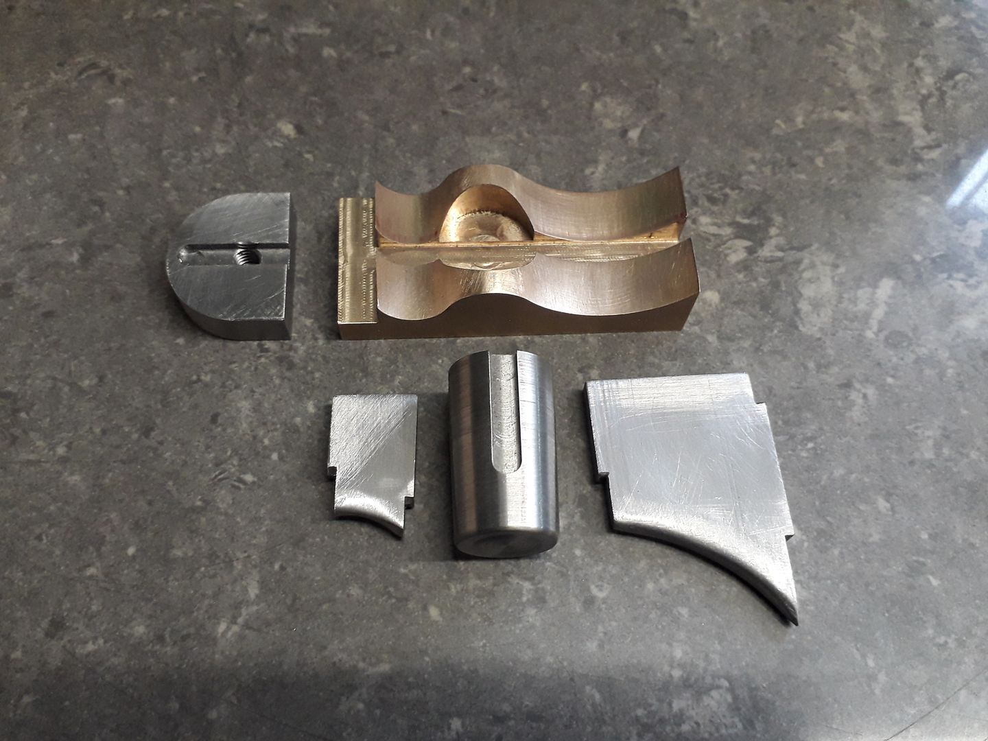
25215 forum posts 3105 photos 1 articles | I wanted a "tee" shaped part similar to a plumbing tee where the 3 branches flow into each other rather than an abrupt junction for the top of the column of the engine I'm making at the moment.
I could have done a simple cope joint and added the fillets with JBWeld or actually welded it and ground back the welds but thought as I have got the CNC that I may as well use it. The bit of 40x20 flat steel bar was machined to overall size and the holes put in on the manual mill then over to the KX-3 to do the shaping. Just two paths, firstly a clearing one with a 3-flute carbide cutter then the final contour with a 4-flute 1mm corner radius cutter. quite pleased with how it turned out, just a tickle with files and or Dremel to blend in the cuts as I on;y went with 0.5mm stepdown.
|
| Ron Laden | 25/12/2019 11:48:18 |
2320 forum posts 452 photos | Nice work Jason, just a thought and I probably havnt thought this through enough but would using a ball nose cutter on the final cuts leave a smoother surface finish needing less hand finishing, with it been CNC I wonder if it would but maybe not. |
| JasonB | 25/12/2019 12:48:02 |
25215 forum posts 3105 photos 1 articles | Hi Ron, Yes generally the larger the radius of teh cutter the smoother the finish will be but there are other things to consider. Firstly this shows the part enlarged in the CAM program as I cut it with the 6mm dia 1mm corner radius cutter, the couple of odd blue bits are in excess of 0.1mm of finished size, all the green is withing 0.1mm of finished size so not really that rough at least in my book and as I want to simulate a casting a bit of variance when hand finished will be a bonus.
One simple way I could get it smoother is to reduce the step down between cuts, I did it at 0.5mm stepdown but this pic shows it done at 0.25mm stepdown, blue has gone and the green surfac elooks smoother but it would take twice as long to machine
If I now run it with a 6mm ball nose cutter the green surface is even smoother but there are two isssues. Firstly on the more horizontal surfaces where the middle of the cutter is doing the work the cutting edges are not moving very fast so feeds may need to be slower and secondly as a lot of ball nose cutters are 2 flute then if the chip load is to be kept the same you would need to feed at half the speed so again twice as long to machine though I do have some 4-flute ball ended cutters that would be able to be fed as fast. Ignore the blue bit as I did not fully alter the CAM to suit the ball ended cutter but green is even smoother.
Though you do have to be careful how large a radius you go for as it may not be small enough to get into the corners and to machine down as far as I have you would have more of the cutter below the widest point of the work so less to hold in the vice, this is with a 20mm ball nose which leaves a lot in the corners and the blue line along the edge is where I can't get to without hitting the vice
So lots of factors to think about and that also depend on the cutters you have and how long the machine will be tied up which affects commercial users more than us hobby users |
| Ron Laden | 25/12/2019 20:20:55 |
2320 forum posts 452 photos | Thanks Jason, quite a few factors there that I didnt consider. |
| JasonB | 27/12/2019 19:57:54 |
25215 forum posts 3105 photos 1 articles | Another part for the same engine, this time the valve block at the base of the column cut from a block of bronze. Final contour done with a 6mm 4-flute ball nose cutter for Ron. |
| Ron Laden | 28/12/2019 06:18:43 |
2320 forum posts 452 photos | That's quite some shape Jason, looks to have gone well. The ball nose seems to have finished off nicely, any issues in using it?
|
| JasonB | 28/12/2019 07:14:36 |
25215 forum posts 3105 photos 1 articles | No it was cutting very well though you may be able to see that the CAM program stops it short of going right to the bottoms of the two "U" shapes so the very end was not being used. It's all soldered up now and ready for final machining today. |
| Michael Gilligan | 28/12/2019 08:39:55 |
 23121 forum posts 1360 photos | Very impressive, Jason The reflections of the tool in the surface of the workpiece, especially so MichaelG. |
| JasonB | 28/12/2019 18:26:42 |
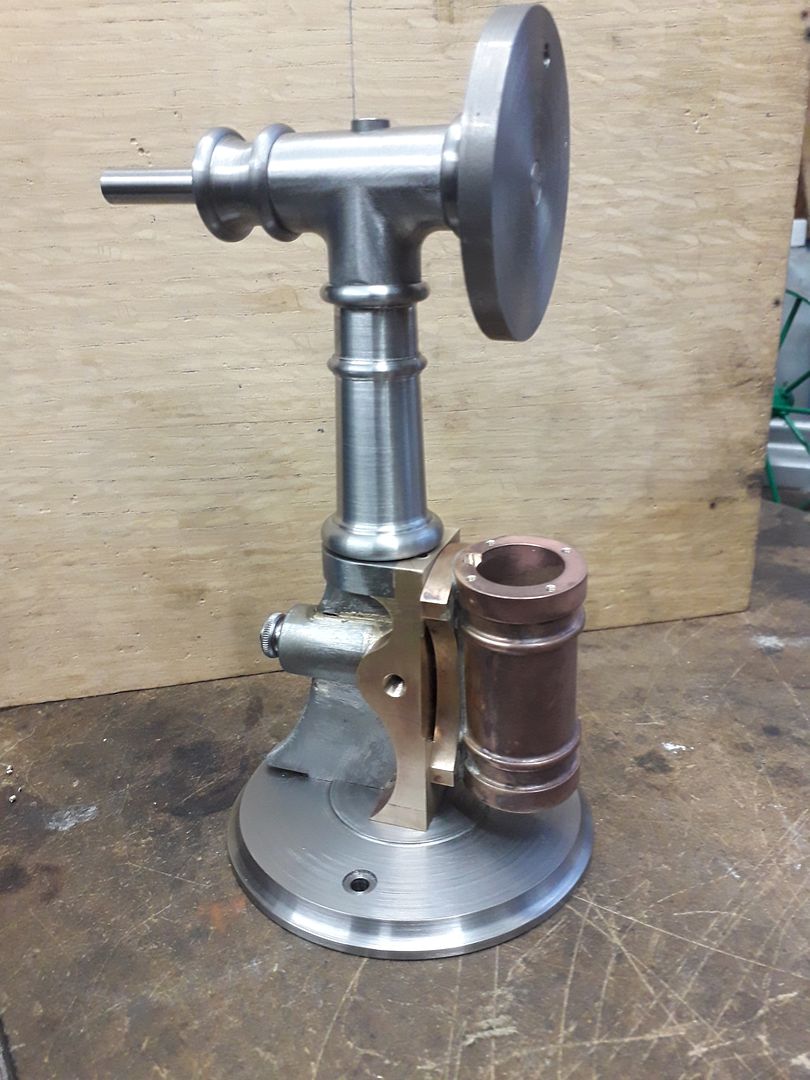
25215 forum posts 3105 photos 1 articles | Thank's michael, I was happy how all three tools cut with very little sign of any burrs which are always an indication of a blunt tool particularly on bronze. The straight ones had done previous work but the ball ended one was new which also helped. Seems a pity to have to take a file to it and then discolour it by silver soldering but needs must and as it will get painted anyway I'm happy. Rest of teh bits to be soldered
And after final machining of the fabricated "casting" with the rest of the engine to date, you can also see the "tee" at the top that I showed a couple of days ago.
Edited By JasonB on 28/12/2019 18:27:20 |
| Ron Laden | 29/12/2019 13:29:55 |
2320 forum posts 452 photos | Nice work Jason, certainly looking like it all came from castings. |


Please login to post a reply.
Magazine Locator
Want the latest issue of Model Engineer or Model Engineers' Workshop? Use our magazine locator links to find your nearest stockist!
Sign up to our Newsletter
Sign up to our newsletter and get a free digital issue.
You can unsubscribe at anytime. View our privacy policy at www.mortons.co.uk/privacy
Latest Forum Posts
- hemingway ball turner
04/07/2025 14:40:26 - *Oct 2023: FORUM MIGRATION TIMELINE*
05/10/2023 07:57:11 - Making ER11 collet chuck
05/10/2023 07:56:24 - What did you do today? 2023
05/10/2023 07:25:01 - Orrery
05/10/2023 06:00:41 - Wera hand-tools
05/10/2023 05:47:07 - New member
05/10/2023 04:40:11 - Problems with external pot on at1 vfd
05/10/2023 00:06:32 - Drain plug
04/10/2023 23:36:17 - digi phase converter for 10 machines.....
04/10/2023 23:13:48 - More Latest Posts...
- View All Topics
Support Our Partners


Shopping Partners
Subscription Offer

Latest "For Sale" Ads
- Reeves** - Rebuilt Royal Scot by Martin Evans
by John Broughton
£300.00 - BRITANNIA 5" GAUGE James Perrier
by Jon Seabright 1
£2,500.00 - Drill Grinder - for restoration
by Nigel Graham 2
£0.00 - WARCO WM18 MILLING MACHINE
by Alex Chudley
£1,200.00 - MYFORD SUPER 7 LATHE
by Alex Chudley
£2,000.00 - More "For Sale" Ads...
Latest "Wanted" Ads
- D1-3 backplate
by Michael Horley
Price Not Specified - fixed steady for a Colchester bantam mark1 800
by George Jervis
Price Not Specified - lbsc pansy
by JACK SIDEBOTHAM
Price Not Specified - Pratt Burnerd multifit chuck key.
by Tim Riome
Price Not Specified - BANDSAW BLADE WELDER
by HUGH
Price Not Specified - More "Wanted" Ads...
Get In Touch!
Do you want to contact the Model Engineer and Model Engineers' Workshop team?
You can contact us by phone, mail or email about the magazines including becoming a contributor, submitting reader's letters or making queries about articles. You can also get in touch about this website, advertising or other general issues.
Click THIS LINK for full contact details.
For subscription issues please see THIS LINK.
Digital Back Issues


Donate

 Register
 Log-in
Model Engineer Magazine
- Percival Marshall
- M.E. History
- LittleLEC
- M.E. Clock

ME Workshop
- An Adcock
- & Shipley
- Horizontal
- Mill

Subscribe Now
- Great savings
- Delivered to your door

Pre-order your copy!
- Delivered to your doorstep!
- Free UK delivery!
All Forum Topics > CNC machines, Home builds, Conversions, ELS, automation, software, etc tools > Further Adventures with the Sieg KX3 & KX1