Forum sponsored by:

Mc Donald Model tractor
Single cylinder semi diesel
| Four stroke Fred | 08/04/2021 09:24:29 |
 322 forum posts 305 photos | Today I cast another front hub as a spare and to be used to set up machining operations. As they say “practice makes perfect “ and it doesn’t take much longer to make three than two when all the casting equipment is out. The photo shows milling the spoke flats making use of an adjustable angle plate and digital protractor. If all goes well one wheel should assembled by tomorrow night! Fred.
|
| Four stroke Fred | 13/04/2021 05:12:17 |
322 forum posts 305 photos | One front wheel made one more to go. The thought of making these wheels have been hanging over my head like a big black cloud for quite some time but now at least I know they can be made! The front wheels on the full size tractor did not have the outer rim disc fitted but the owners hand book shows that some tractors had them ,obviously to help with the steering. The 3mm screws used to hold the spokes to the hub have had the heads reshaped ,using a form tool, to represent rivets and the heads will have the slots filled in later. Fred.
|
| Four stroke Fred | 16/04/2021 08:56:11 |
322 forum posts 305 photos | These are the laser cut parts for the front axle beam. The are made from mild steel - 3.0mm for the outer parts and 6.0mm for the centre section. They are designed using CAD and saved as a DXF file then taken to the laser cutter where he works his magic! These parts will be riveted and silver soldered together with the parts that form the king pins. Both of the front wheels have now been made and I hope to have the second rear wheel completed next week. It will be good to see the model standing on its own wheels and when the steering is connected that will be even better. Fred.
|
| Roger Best | 18/04/2021 15:57:54 |
 406 forum posts 56 photos |
Edited By Roger Best on 18/04/2021 15:58:20 |
| Alan Jackson | 18/04/2021 18:35:44 |
 276 forum posts 149 photos | I have just started to go through this fantastic model being built. What wonderful skills you are showing us all. Thanks Fred Alan |
| Four stroke Fred | 23/04/2021 09:00:36 |
322 forum posts 305 photos | Thanks Alan and Roger for the feed back and I am pleased you enjoy reading about the Mc Donald tractor. The photographs show progress so far on the front axle beam. There is still some minor work to do and then make all the parts for steering gear. The parts shown in a previous picture were cleaned, clamped together and then drilled for six 1/16” steel rivets to hold the parts together for silver soldering. The job was pre fluxed before the rivets were tapped over as this left a path for the solder to flow through. “ Liquid Steel “ ( epoxy) was the used to fillet the inside edges to give the effect of a casting. The perch ( the black part on the axle) is fabricated from six pieces of machined steel silver soldered together. I now have all the laser cut parts on hand to complete the mudguards and these will keep me busy for the next few weeks. |
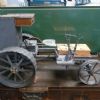
| Four stroke Fred | 05/05/2021 07:47:53 |
322 forum posts 305 photos | The Mc Donald now has four wheels but the steering has yet to be connected up. The screws used in the beam axle are temporary and will be replaced when I have made them. The next stage is to add the mudguards, fit the seat and bolt the tool boxes in place. I have to admit that I had to ask a friend to fusion weld the curved parts of the mudguard to the vertical parts as I don’t posses a TIG welder. On the full size tractor this joint has a curve and silver solder would not make a satisfactory job where as welding will give more “ meat” to the joint and can be filled to shape later. At this stage I do have to think about the engine as it forms an integral part of the machine and has many parts bolted to it and these can’t be made until the engine is in place ( or at least the external shape). These parts include the fuel tank, lubricator, air box and the drives to the gearbox and cooling fan. As a result there may seem to be a lull in proceedings but I will be busy with CAD for a few days. |
| Adrian R2 | 05/05/2021 10:45:38 |
| 196 forum posts 5 photos | Fascinating watching this come together and the thought that is going into each piece. A question on the front axle - why did you decide to make it from plate sections? Presumably you thought cast aluminium would not be strong enough around the pivot, but why not machine from solid steel? Edited By Adrian R2 on 05/05/2021 10:46:21 |
| Four stroke Fred | 05/05/2021 11:42:23 |
322 forum posts 305 photos | Good Day Adrian and thanks for your interest in the tractor. I did think of casting the front axle beam in aluminium but thought that it would not be strong enough particularly around the king pin area. As I don’t mind embracing “ new” techniques and methods I decided these parts could be laser cut ,with me providing the DXF files to the laser cutter. The fabricated part is certainly strong enough and I think would have taken less time to make than machining from a solid lump of steel or aluminium. ( I don’t have CNC machines but wish I did). When designing and making parts such as this there are often many options with the final choice depending on the equipment, experience and time and as you get older the last factor is important ! Regards, Fred. . |
| Four stroke Fred | 07/05/2021 09:02:42 |
322 forum posts 305 photos |
Fred
|
| Dominic Bramley | 07/05/2021 09:25:06 |
| 60 forum posts 1 photos | Still following and still enjoying! Have been flicking back to page 1 to to compare the pictures of the full size machine. The model is amazingly accurate!
Regards Dom |
| Four stroke Fred | 07/05/2021 11:16:55 |
322 forum posts 305 photos | Good Day Dom, I am lucky in that the full size tractor is not far from my home and so far I have spent 20 hours making sketches and taking photographs. If I am not sure how a part works or it’s dimensions I just pop down to the farm a round trip of 34 klm. I am very grateful to the local owner for allowing me to do this as with out these visits it would be difficult to gain the required information - he is also interested to see a model of his tractor being made! Fred. |
| Four stroke Fred | 18/05/2021 09:22:29 |
322 forum posts 305 photos |
Fred.
|
| Michael Gilligan | 18/05/2021 09:54:11 |
 23121 forum posts 1360 photos | Getting better all the time !! MichaelG. |
| Adrian R2 | 18/05/2021 10:23:47 |
| 196 forum posts 5 photos | I'm intrigued by the operator controls (model and fullsize) - are there any pedals or is it all done by hand while standing on the platform like a traction engine? I can see gear level and another lever so is that brake or clutch and how did one start and stop it? Edited By Adrian R2 on 18/05/2021 10:24:23 |
| Four stroke Fred | 18/05/2021 10:45:10 |
322 forum posts 305 photos | Good Day Adrian, The gear lever is at the rear of the gearbox and is in a “H” pattern (with H on its side). Forward right is reverse, forward left is low, back left is second gear and forward right is top. The throttle will be a hand control on the top left near the bonnet. The lever on the right is the clutch and there are no foot pedals and there are no brakes. Brakes were available on later models and consisted of a band brake of an extended shaft from the gearbox but the tractor that this model is scaled from does not have brakes. Perhaps it never went fast enough to warrant them ! Fred. |
| Adrian R2 | 18/05/2021 13:50:19 |
| 196 forum posts 5 photos | Thanks Fred, that makes my uncle's Field Marshall look positively modern. I guess there can't be any hills on the farm where it lives then? We have pretty flat land as well so brakes don't get used a lot but they are still nice to have when manouvering or hitching up. |
| Four stroke Fred | 29/05/2021 09:12:22 |
322 forum posts 305 photos |
|
| Roger B | 29/05/2021 16:13:30 |
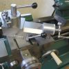
 244 forum posts 105 photos | Excellent How many teeth are on the ratchet wheel, in other words what is the reduction from crankshaft speed? 3.2 x 3.4 mm is quite a lot of oil. |
| Four stroke Fred | 30/05/2021 00:09:47 |
322 forum posts 305 photos | Roger the present ratchet wheel has 19 teeth but if this needs to be increased it can be replaced. The lever that will be attached to the drive shaft is adjustable and will control the amount of movement on the clutch/ ratchet. It is hoped that the engine can be made to run at quite low realistic speeds and give sounds that are characteristic of the full size tractor. Fred |


Please login to post a reply.
Magazine Locator
Want the latest issue of Model Engineer or Model Engineers' Workshop? Use our magazine locator links to find your nearest stockist!
Sign up to our Newsletter
Sign up to our newsletter and get a free digital issue.
You can unsubscribe at anytime. View our privacy policy at www.mortons.co.uk/privacy
Latest Forum Posts
- hemingway ball turner
04/07/2025 14:40:26 - *Oct 2023: FORUM MIGRATION TIMELINE*
05/10/2023 07:57:11 - Making ER11 collet chuck
05/10/2023 07:56:24 - What did you do today? 2023
05/10/2023 07:25:01 - Orrery
05/10/2023 06:00:41 - Wera hand-tools
05/10/2023 05:47:07 - New member
05/10/2023 04:40:11 - Problems with external pot on at1 vfd
05/10/2023 00:06:32 - Drain plug
04/10/2023 23:36:17 - digi phase converter for 10 machines.....
04/10/2023 23:13:48 - More Latest Posts...
- View All Topics
Support Our Partners


Shopping Partners
Subscription Offer

Latest "For Sale" Ads
- Reeves** - Rebuilt Royal Scot by Martin Evans
by John Broughton
£300.00 - BRITANNIA 5" GAUGE James Perrier
by Jon Seabright 1
£2,500.00 - Drill Grinder - for restoration
by Nigel Graham 2
£0.00 - WARCO WM18 MILLING MACHINE
by Alex Chudley
£1,200.00 - MYFORD SUPER 7 LATHE
by Alex Chudley
£2,000.00 - More "For Sale" Ads...
Latest "Wanted" Ads
- D1-3 backplate
by Michael Horley
Price Not Specified - fixed steady for a Colchester bantam mark1 800
by George Jervis
Price Not Specified - lbsc pansy
by JACK SIDEBOTHAM
Price Not Specified - Pratt Burnerd multifit chuck key.
by Tim Riome
Price Not Specified - BANDSAW BLADE WELDER
by HUGH
Price Not Specified - More "Wanted" Ads...
Get In Touch!
Do you want to contact the Model Engineer and Model Engineers' Workshop team?
You can contact us by phone, mail or email about the magazines including becoming a contributor, submitting reader's letters or making queries about articles. You can also get in touch about this website, advertising or other general issues.
Click THIS LINK for full contact details.
For subscription issues please see THIS LINK.
Digital Back Issues


Donate

 Register
 Log-in
Model Engineer Magazine
- Percival Marshall
- M.E. History
- LittleLEC
- M.E. Clock

ME Workshop
- An Adcock
- & Shipley
- Horizontal
- Mill

Subscribe Now
- Great savings
- Delivered to your door

Pre-order your copy!
- Delivered to your doorstep!
- Free UK delivery!
All Forum Topics > Work In Progress and completed items > Mc Donald Model tractor