Forum sponsored by:

Stuart Twin Victoria (Princess Royal) Mill Engine
| Ramon Wilson | 11/07/2023 20:32:38 |
 1655 forum posts 617 photos | Yes, there's nothing wrong with making them from solid just that it requires more material and a lot more machining. A mistake somewhere along the way means a likely restart and obviously more material. The further you get into the machining the more there is to lose. The Corliss con rod came out of one piece as did the marine engine rods. The double diagonal rods were different to each other and much shorter that average but fish bellied and took quite some machining It was a big step back when I realised this one was a scrapper though
As always Doc it's down to choice - good luck with them however you go about it |
| Dr_GMJN | 12/07/2023 22:35:44 |
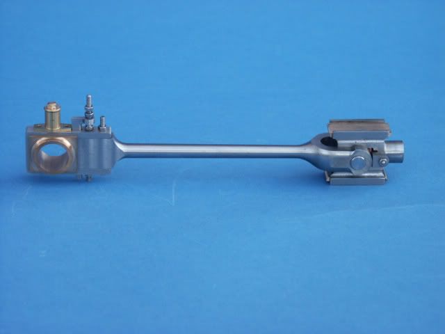
 1602 forum posts | I like the idea of fish-bellied rods rather than straight-tapered, so hopefully I’ll end up with something like Ramon’s engine. Id like to stick with machined from solid, but where do you fit the carrier if machining between centres? Do you clamp the carrier around the faceplate end, and constantly swap the workpiece as you turn the tapers, hopefully not damaging anything? Presumably the tapers are done by re-setting the topslide rather than offsetting the tailstock? Is it a question of marking the start and end of the tapers with a marker and working to scribed lines, then swapping the ends and repeating the cuts? I think I’ll use the parallel middle and two angled cut method (5 facets in total per rod) then smooth them. I will have to do a drawing to get the marking out right. Thanks.
|
| JasonB | 13/07/2023 07:08:09 |
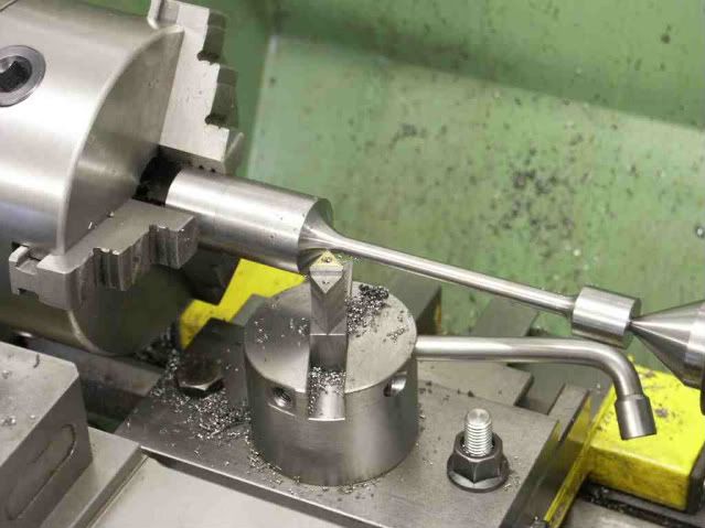
 25215 forum posts 3105 photos 1 articles | Doc if you follow the links I posted at the bottom of the previous page to the Real in particular and James Coombes you will see that I don't use a carrier, I mark with a Sharpie. The three facets that I show is more than adequate for these small rods and the angles involved See the other thread linked to To save upsetting the tailstock I sometimes use my boring head to offset for the tapers but as they are not that long and you will end up hand finishing then the topslide is fine and it's what I used on the Real which is exactly the same as the Victoria part You will also see that I have excess material at each end that can be used to clamp a drive dog to or simply hold in a chuck so no risk of marking a finished surface or having ctr holes where you don't want them
Edited By JasonB on 13/07/2023 07:10:51 |
| Dr_GMJN | 13/07/2023 13:09:47 |
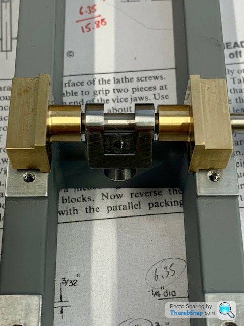
1602 forum posts | Thanks Jason, yes I saw the links now. So as far as I can see the procedure would be: 1) Mill my square stock to the rectangular section of the largest end (the stock I have is oversized). 2) Cut to overall length + c.10mm on each end. 3) Put in 4-jaw, centre drill one end, and extend it out of the chuck to be supported by the tailstock. 4) Mark out the ends of the radii at each end of the round section. Not sure from here, because I can't figure out how to simultaneously turn the end blend radii to be the right diameter and to the right run-out length at the rectangular bosses. I can't turn to diameter first, because if it ends up being too far away from the end, I'll have a parallel section rather than a taper blending to a radius. I'm going to get an 8mm diameter button tool for the radii, because I like the look of a larger radius there. Thanks.
|
| JasonB | 13/07/2023 13:32:04 |
25215 forum posts 3105 photos 1 articles | 1 You really only need to mill the ends to their rectangular shape 2. Put the holes and slot for the fork in while you still have 4 sides to hold in the vice which make sit easy to do in the mill 3 Cut, face and ctr 4 You can scribe a line where the big end rectangular section ends. Likewise the extend of the forked end's "U" shape can be marked by scribing around a disc or bar end. 5 Turn parallel between the marks to the fattest diameter of your belly 6 Cad will give you angles to end up with the desired waist diameter at each end but probably easier to set the topslide over to a larger angle than needed. Turn the taper working into an end and see how far along the rod it feathers out once you have got the desired waist diameter, adjust angle of topslide and cut again until it runs out at 1/3rd distance
4mm radius sounds quite large for that size rod, you may get an odd looking side to the big end rectangles and chatter risk goes up. I don't often use anything more than 1.5mm radius on rods, on the odd occasion I have needed bigger it's been a lot and I used a ball turner
|
| JasonB | 13/07/2023 13:48:59 |
25215 forum posts 3105 photos 1 articles | Oh I just looked at the PR drawings and it is not a fish belly that is fatter in the middle as the diameters at each end are different, and it'd not forked at the end like the Victoria. Bending the stock by rigidly holding the big end and offsetting the small end and then using the carriage power feed will give the classic taper or "entasis" but again by just turning a taper just over half way along and then blending with the file will give a very close representation. See the short leg of the "tee" shaped one on the James Coombes |
| Dr_GMJN | 13/07/2023 15:09:13 |
1602 forum posts | Thanks Jason. The PR drawings call for a 5/32" radius at each end (about 3.97mm). Yes, the drawings show a straight-taper rod, but I would like to change this to a fish bellied type, as per Ramon's model. |
| JasonB | 13/07/2023 18:20:53 |
25215 forum posts 3105 photos 1 articles | Bear in mind that Ramon's Twin Vic and mine were for the forked end rods where the waist is the same diameter at each end, you have differing diameters on PR so the belly needs to be done differently |
| Dr_GMJN | 14/07/2023 16:31:51 |
1602 forum posts | Hmm it looks like a 4mm radius at the ends is a minimum in order to get a nice blend without the corners of the bosses being slightly concave with pointy corners (I want the blends to run out over all four faces of each end rather the being a small fillet against rectangular faces. |
| JasonB | 14/07/2023 16:36:34 |
25215 forum posts 3105 photos 1 articles | Whatever radius you use it should not end up concave (undercut) as you feed in with the cross slide which is 90deg across the lathe |
| Dr_GMJN | 14/07/2023 17:54:02 |
1602 forum posts | Posted by JasonB on 14/07/2023 16:36:34:
Whatever radius you use it should not end up concave (undercut) as you feed in with the cross slide which is 90deg across the lathe Yes I guess so. TBH I’m still puzzling over how to get length and diameter both correct and equal on both rods. The tapers have no straight line definition of where the radius runs out. If I turn to the right small diameter, but the length is wrong, I’d then have to move along into the ends (potentially giving the concave geometry, then out sideways to get rid of that, but that would then change the radius run-out length on the blocks. Im thinking find the centre of the rod by measuring from one end, then turn the whole circular length to the maximum central O/D, then mark the beginning of the taper onto an area of felt-tipped pen, set the topslide to the correct angle and turn up to the marked lines, then set topslide extension (hoping that by the ends, everything is right and runs out to the blocks. All that would rely on setting lengths to the drawing, and hoping I can accurately set the topslide to a very specific angle. |
| JasonB | 14/07/2023 18:32:16 |
25215 forum posts 3105 photos 1 articles | As I said start from the shoulders and work into the middle increasing the angle until you hit the sharpie line. You do not need micron accuracy as to where the taper meets the mid section, after all you will only be blending by hand with a file and using your eye to judge what looks right. You have CAD so should easily be able to work out offsets and infeed if you feel you need them, though I tend to just work to a light scriber mark on one side of the rectangular portion. Just make a note of any handwheel readings for the first one and then repeat for the second. As I have said a few times the fat part of the belly won't be mid rod as diameters at each end are different. Think of it as a long harrow ellipse if you slice off one end at 1/4" and the other at 5/16" your slice lines will be different dimensions from the mid point. |
| Dr_GMJN | 14/07/2023 20:05:00 |
1602 forum posts | Sorry Jason I don’t fully understand: If I start at a shoulder and feed in with a button tool, I’m simultaneously reducing diameter and shortening the rectangular bit. Aren’t the chances of hitting the line, and the correct diameter at the same time pretty slim? Ive CADed up a fish bellied design, and made the lengths to the blend centres equal. Why would the diameters be different at each end? After all, I’m defining them as the same. The blocks are different sizes, but the blends run into and out of them however they need to. |
| JasonB | 14/07/2023 20:40:12 |
25215 forum posts 3105 photos 1 articles | Its a case of playing with the hand wheels to avoid cutting into the rectangle as you feed in. In practice you start a little away from the shoulder feed in then move to the shoulder and then along the taper. Different diameters on the Princess royal drawing due to him using a chunkier big end. To get the look of entasis just blend the parallel section with the 1deg taper which is the preferable "look". To do a fish belly if that is what you want make the fat part where I have indicated otherwise the rod may look a bit spindly where it joins the big end
|
| Dr_GMJN | 15/07/2023 13:58:35 |
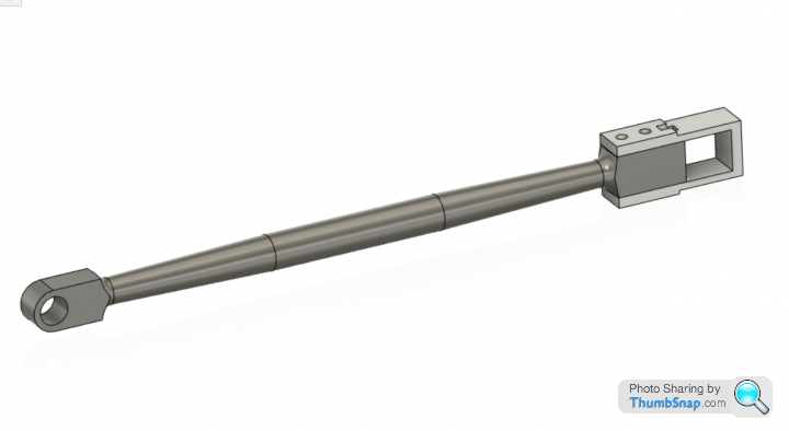
1602 forum posts | OK this is the best compromise I can make for a symmetrical fish-bellied rod. No blend filing shown. It's a 3 degree overall taper at each end (topslide set to 1.5 degrees). |
| Dr_GMJN | 15/07/2023 16:35:58 |
1602 forum posts | Got the taper pins and reamer. Then, while figuring out how to hold the forks and shaft for drilling, found an issue: For some reason years ago I changed the four hole offsets for the slide bars to be further out. I think I might have done this becasue as drawn, the round mounting pillars overhang the inner base walls a bit, and moving the holes makes them look much better. |


Please login to post a reply.
Magazine Locator
Want the latest issue of Model Engineer or Model Engineers' Workshop? Use our magazine locator links to find your nearest stockist!
Sign up to our Newsletter
Sign up to our newsletter and get a free digital issue.
You can unsubscribe at anytime. View our privacy policy at www.mortons.co.uk/privacy
Latest Forum Posts
- *Oct 2023: FORUM MIGRATION TIMELINE*
05/10/2023 07:57:11 - Making ER11 collet chuck
05/10/2023 07:56:24 - What did you do today? 2023
05/10/2023 07:25:01 - Orrery
05/10/2023 06:00:41 - Wera hand-tools
05/10/2023 05:47:07 - New member
05/10/2023 04:40:11 - Problems with external pot on at1 vfd
05/10/2023 00:06:32 - Drain plug
04/10/2023 23:36:17 - digi phase converter for 10 machines.....
04/10/2023 23:13:48 - Winter Storage Of Locomotives
04/10/2023 21:02:11 - More Latest Posts...
- View All Topics
Support Our Partners


Shopping Partners
Subscription Offer

Latest "For Sale" Ads
- Reeves** - Rebuilt Royal Scot by Martin Evans
by John Broughton
£300.00 - BRITANNIA 5" GAUGE James Perrier
by Jon Seabright 1
£2,500.00 - Drill Grinder - for restoration
by Nigel Graham 2
£0.00 - WARCO WM18 MILLING MACHINE
by Alex Chudley
£1,200.00 - MYFORD SUPER 7 LATHE
by Alex Chudley
£2,000.00 - More "For Sale" Ads...
Latest "Wanted" Ads
- D1-3 backplate
by Michael Horley
Price Not Specified - fixed steady for a Colchester bantam mark1 800
by George Jervis
Price Not Specified - lbsc pansy
by JACK SIDEBOTHAM
Price Not Specified - Pratt Burnerd multifit chuck key.
by Tim Riome
Price Not Specified - BANDSAW BLADE WELDER
by HUGH
Price Not Specified - More "Wanted" Ads...
Get In Touch!
Do you want to contact the Model Engineer and Model Engineers' Workshop team?
You can contact us by phone, mail or email about the magazines including becoming a contributor, submitting reader's letters or making queries about articles. You can also get in touch about this website, advertising or other general issues.
Click THIS LINK for full contact details.
For subscription issues please see THIS LINK.
Digital Back Issues


Donate

 Register
 Log-in
Model Engineer Magazine
- Percival Marshall
- M.E. History
- LittleLEC
- M.E. Clock

ME Workshop
- An Adcock
- & Shipley
- Horizontal
- Mill

Subscribe Now
- Great savings
- Delivered to your door

Pre-order your copy!
- Delivered to your doorstep!
- Free UK delivery!
All Forum Topics > Work In Progress and completed items > Stuart Twin Victoria (Princess Royal) Mill Engine