Forum sponsored by:

Stuart Twin Victoria (Princess Royal) Mill Engine
| Dr_GMJN | 23/03/2023 21:19:22 |
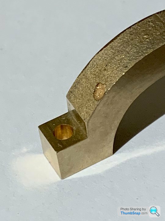
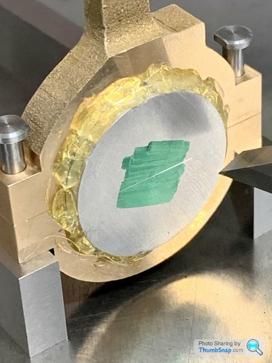
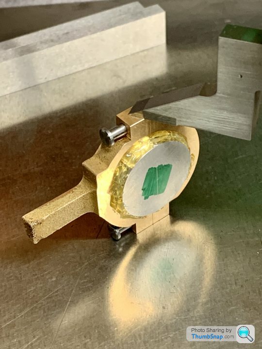
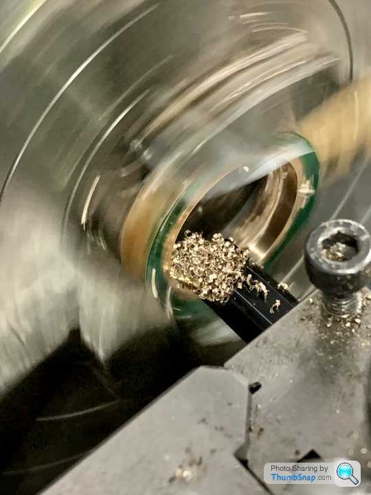
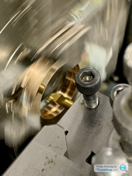
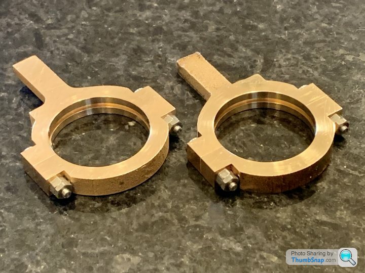
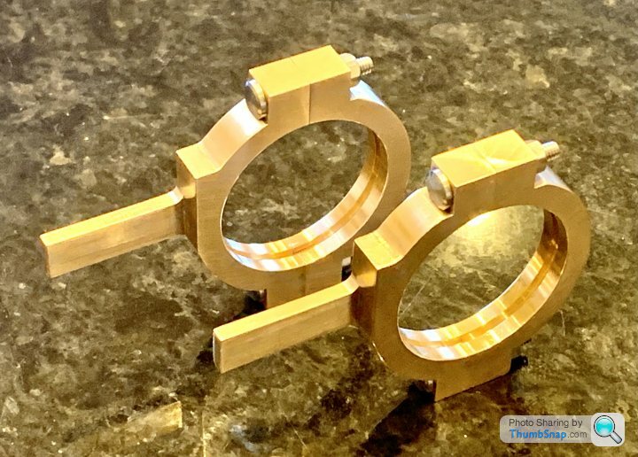
 1602 forum posts | Got the main flat surfaces completed on both straps, and machined the holes. Everything lines up fine, and all but one of the holes look to be good quality (at least when assembled using a twist drill as a spigot). The remaining hole has a slight bulge, but it’s cylindrical over about 270 degrees so it should be ok at least in function. I don’t think the holes are worth reaming after all: |
| JasonB | 24/03/2023 06:50:02 |
 25215 forum posts 3105 photos 1 articles | If you have any offcuts of the same material you could plunge mill a hole and turn up a small plug to Loctite into place |
| Dr_GMJN | 24/03/2023 07:19:20 |
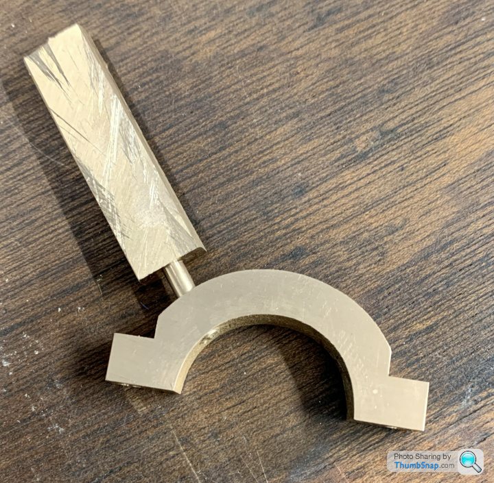
1602 forum posts | I don’t have any off-cuts, but I wonder if it’s the same material as the main bearing pedestals that I no longer need? The other thing is I’m not that keen on the flat bar eccentric rods. I’ve seen some with parallel round bar screwed into a flat plate with a boss for the rod, the plate is in turn bolted to the eccentric. If I got some of the right diameter rod I might consider doing that, then I’d have the rectangular tail off-cuts spare. I might see how much material I’d have for a pad on the eccentrics and take it from there.
|
| Dr_GMJN | 25/03/2023 21:50:24 |
1602 forum posts | Would it be possible to solder the plug in place rather than Loctite? I guess I’ll be soldering the joint faces anyway, so I could do the plug at the same time before final machining. |
| JasonB | 26/03/2023 07:07:31 |
25215 forum posts 3105 photos 1 articles | You could do, just be careful that any hot flux in the bottom of the hole does not pop the plug out. I thought you were going to just bolt it together for boring? |
| Dr_GMJN | 26/03/2023 09:06:45 |
1602 forum posts | Posted by JasonB on 26/03/2023 07:07:31:
You could do, just be careful that any hot flux in the bottom of the hole does not pop the plug out. I thought you were going to just bolt it together for boring?
I think the bearing pedestals are the same material as the straps, so I guess I could bore right through and plug to avoid any push-back, then machine? |
| JasonB | 26/03/2023 10:00:45 |
25215 forum posts 3105 photos 1 articles | Yes likely to be the same so would not affect the cut |
| Weary | 26/03/2023 11:36:26 |
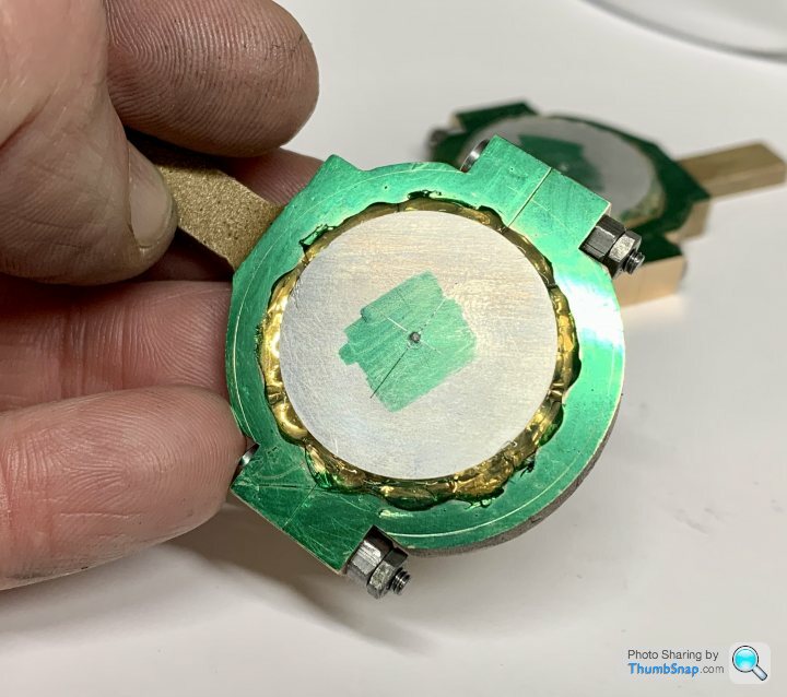
| 421 forum posts 1 photos | Re: your 'plug' to cover strap-blemish: How about drilling all the way through a small size (say 1mm), then drilling the 'plug' size part way through. This would allow flux to escape down the 'pilot vent' and save re-machining inside the straps? The pilot hole would be invisible once assembled. Additionally I note that your flaw appears to be very close to the strap-edge = watch for drill break-through! Maybe worth using a suitable sized end-mill as a drill? Regards, Phil |
| Dr_GMJN | 26/03/2023 14:39:09 |
1602 forum posts | Posted by Weary on 26/03/2023 11:36:26:
Re: your 'plug' to cover strap-blemish: How about drilling all the way through a small size (say 1mm), then drilling the 'plug' size part way through. This would allow flux to escape down the 'pilot vent' and save re-machining inside the straps? The pilot hole would be invisible once assembled. Additionally I note that your flaw appears to be very close to the strap-edge = watch for drill break-through! Maybe worth using a suitable sized end-mill as a drill? Regards, Phil Thanks Phil, yes the idea is to use the end mill again - I realise it's close to the edge, but at least the flaw tapers, so the very edge of it might get machined away anyway. I'll see how it goes with the milling - I might just mill right through it it's possible. As you say whatever the inner end looks like, won't be visibe anyway.
|
| Dr_GMJN | 26/03/2023 14:42:42 |
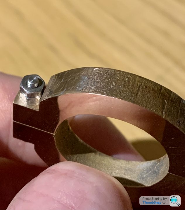
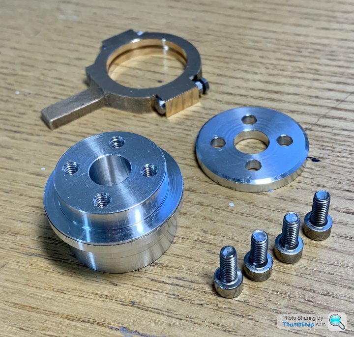
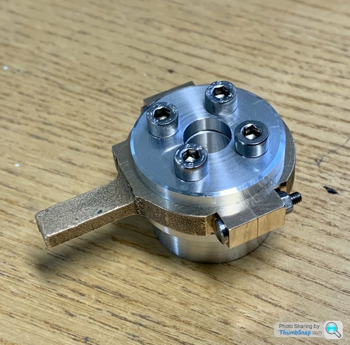
1602 forum posts | I got the bolts made today:
Unfortunately the I don't think there's enough room to make a flanged boss for the eccentric rod, so I'll stick with the rectangular ones as per the article. |
| Dr_GMJN | 29/03/2023 23:04:55 |
1602 forum posts | Still struggling a bit with the straps - a bit of fettling needed tonight, but I think I’m getting there. |
| Dr_GMJN | 31/03/2023 14:49:40 |
1602 forum posts | I guess the reason for the separate central ring is to make machining to a good fit easier, since the eccentric boss can be turned in one pass rather from each side? Presumably though because of the fitted bolts and lock-nuts, a tight fit can to some extent be compensated for?
|
| JasonB | 31/03/2023 15:17:20 |
25215 forum posts 3105 photos 1 articles | At the expense of contact area |
| Dr_GMJN | 31/03/2023 23:07:17 |
1602 forum posts | I’ll hopefully get to making the eccentrics this weekend. I’ll give the parting tool method a go, although judging the right diameter I think I’ll find tricky. I’m thinking I might turn the outer side of the ridge first, checking fit with half the strap overhanging, then when it’s spot-on, measure and machine the chuck side to the same measurement. |
| Dr_GMJN | 31/03/2023 23:08:12 |
1602 forum posts | I’ll hopefully get to making the eccentrics this weekend. I’ll give the parting tool method a go, although judging the right diameter I think I’ll find tricky. I’m thinking I might turn the outer side of the ridge first, checking fit with half the strap overhanging, then when it’s spot-on, measure and machine the chuck side to the same measurement. |
| Dr_GMJN | 01/04/2023 15:25:33 |
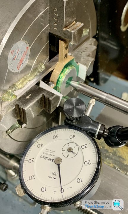
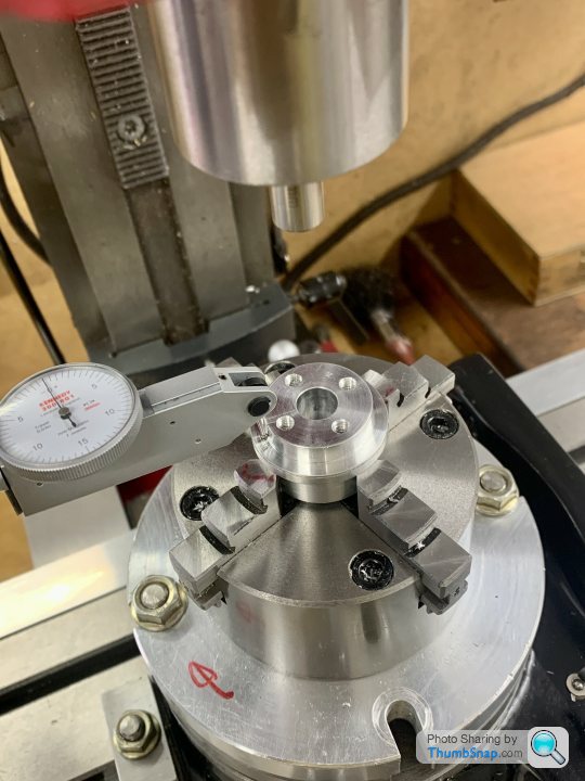
1602 forum posts | Continued with the straps this morning, marking out for setting up in the 4-jaw chuck: |
| Dr_GMJN | 02/04/2023 14:36:59 |
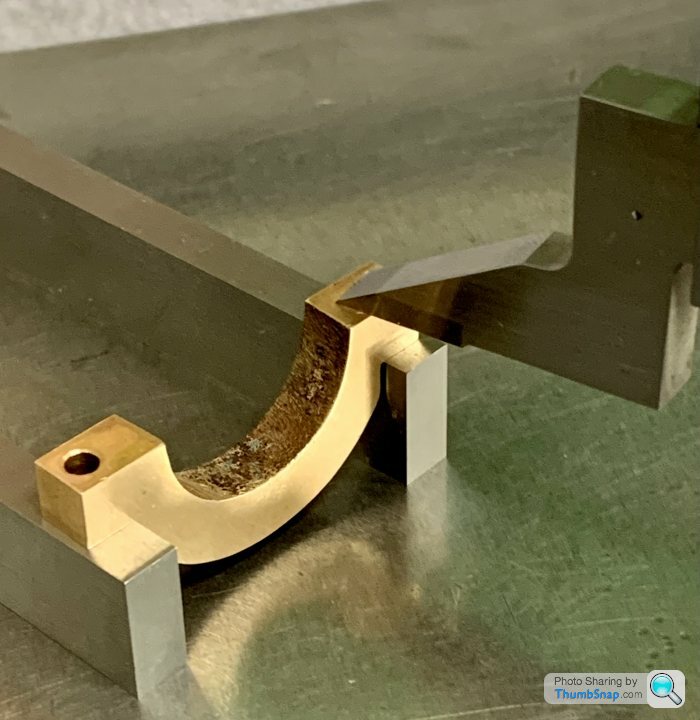
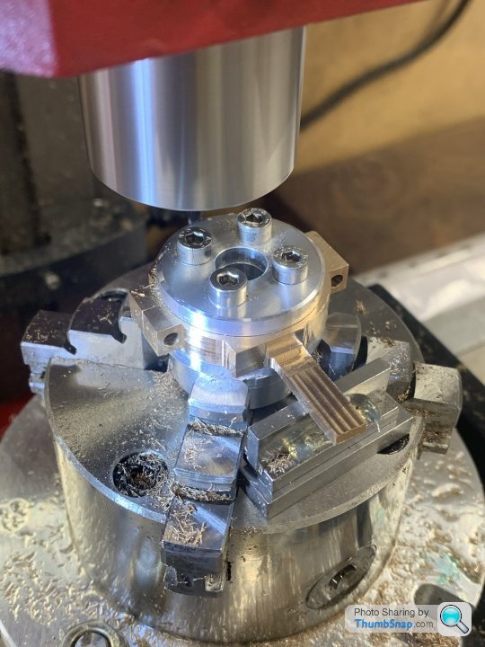
1602 forum posts | Made the fixture for milling the outside profile: |
| Dr_GMJN | 03/04/2023 16:22:53 |
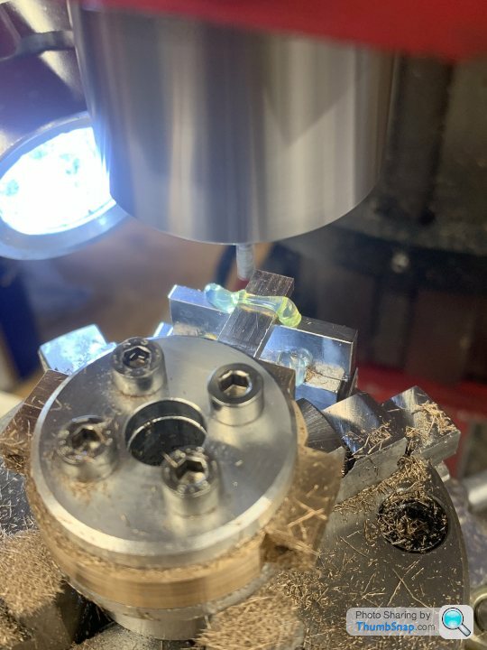
1602 forum posts | Set the fixture in the R/T: |
| Dr_GMJN | 18/04/2023 22:16:26 |
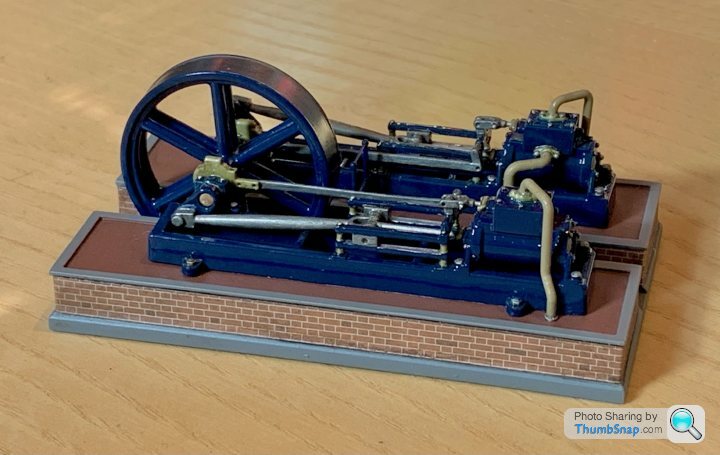
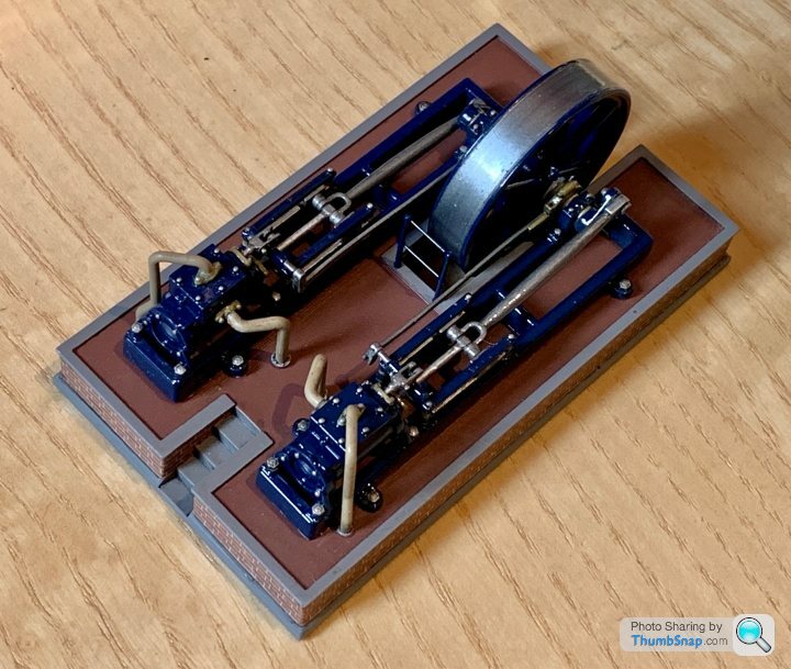
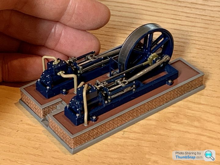
1602 forum posts | It’s finished! Edited By Dr_GMJN on 18/04/2023 22:17:19 |
| JasonB | 19/04/2023 10:30:41 |
25215 forum posts 3105 photos 1 articles | That looks good Doc, what made you change to the smooth faced flywheel?
|


Please login to post a reply.
Magazine Locator
Want the latest issue of Model Engineer or Model Engineers' Workshop? Use our magazine locator links to find your nearest stockist!
Sign up to our Newsletter
Sign up to our newsletter and get a free digital issue.
You can unsubscribe at anytime. View our privacy policy at www.mortons.co.uk/privacy
Latest Forum Posts
- *Oct 2023: FORUM MIGRATION TIMELINE*
05/10/2023 07:57:11 - Making ER11 collet chuck
05/10/2023 07:56:24 - What did you do today? 2023
05/10/2023 07:25:01 - Orrery
05/10/2023 06:00:41 - Wera hand-tools
05/10/2023 05:47:07 - New member
05/10/2023 04:40:11 - Problems with external pot on at1 vfd
05/10/2023 00:06:32 - Drain plug
04/10/2023 23:36:17 - digi phase converter for 10 machines.....
04/10/2023 23:13:48 - Winter Storage Of Locomotives
04/10/2023 21:02:11 - More Latest Posts...
- View All Topics
Support Our Partners


Shopping Partners
Subscription Offer

Latest "For Sale" Ads
- Reeves** - Rebuilt Royal Scot by Martin Evans
by John Broughton
£300.00 - BRITANNIA 5" GAUGE James Perrier
by Jon Seabright 1
£2,500.00 - Drill Grinder - for restoration
by Nigel Graham 2
£0.00 - WARCO WM18 MILLING MACHINE
by Alex Chudley
£1,200.00 - MYFORD SUPER 7 LATHE
by Alex Chudley
£2,000.00 - More "For Sale" Ads...
Latest "Wanted" Ads
- D1-3 backplate
by Michael Horley
Price Not Specified - fixed steady for a Colchester bantam mark1 800
by George Jervis
Price Not Specified - lbsc pansy
by JACK SIDEBOTHAM
Price Not Specified - Pratt Burnerd multifit chuck key.
by Tim Riome
Price Not Specified - BANDSAW BLADE WELDER
by HUGH
Price Not Specified - More "Wanted" Ads...
Get In Touch!
Do you want to contact the Model Engineer and Model Engineers' Workshop team?
You can contact us by phone, mail or email about the magazines including becoming a contributor, submitting reader's letters or making queries about articles. You can also get in touch about this website, advertising or other general issues.
Click THIS LINK for full contact details.
For subscription issues please see THIS LINK.
Digital Back Issues


Donate

 Register
 Log-in
Model Engineer Magazine
- Percival Marshall
- M.E. History
- LittleLEC
- M.E. Clock

ME Workshop
- An Adcock
- & Shipley
- Horizontal
- Mill

Subscribe Now
- Great savings
- Delivered to your door

Pre-order your copy!
- Delivered to your doorstep!
- Free UK delivery!
All Forum Topics > Work In Progress and completed items > Stuart Twin Victoria (Princess Royal) Mill Engine