Forum sponsored by:

Stuart Twin Victoria (Princess Royal) Mill Engine
| Ramon Wilson | 10/03/2023 11:32:05 |
 1655 forum posts 617 photos | Are those 1/72 scale Spitfires? I thought the 1/48 kits they produce were supposed to be some of their better mouldings. 1/72 is far too small for my eyes now, even 48th is pushing it on the smaller types. Lovely work on the bomb bay - just the sort of modelling I like to do myself but shame it's all rarely seen once the model is on it's feet. Have decided my next build (Trumpeter 1/32 F-100F) will be OOB - no after market save he exhaust and a closed cockpit - at 78 detailing at length is just too time consuming. Once the Phantom is on it's base I'll pop a pic or too up. |
| JasonB | 10/03/2023 11:45:38 |
 25215 forum posts 3105 photos 1 articles | Posted by Ramon Wilson on 10/03/2023 11:32:05:
Lovely work on the bomb bay - just the sort of modelling I like to do myself but shame it's all rarely seen once the model is on it's feet. You mean that you don't hang them off the ceiling with bits of fishing line Although I was more into cars and AFVs before the figure modelling I do like to see models before they are painted as you get a better idea of the work done when you can see the plasticard, photo-etch, resin (kit & 3D printed), etc in the flesh. |
| Dr_GMJN | 10/03/2023 13:53:18 |
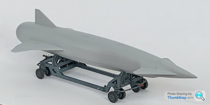
 1602 forum posts | Thanks both - they are 1:72 Spitfires. The Mk1 panel lines are horribly deep, so I'm experimenting with partially filling them with surfacer. The Mk.22 has a horribly moulded nose, which required a lot of flatting, filling and re-scribing to get right. I got a resin printer for Christmas, and I CADded up a trolley for the Blue Steel missile included with the Vulcan (I also made some bomb-bay parts for the Vulcan on it). I scaled online photos and got some key dimensions from a museum. I was quite pleased for a first attempt. I was considering mounting the Vulcan vertically on a wooden base, supported by four acrylic or stainless steel rods up the jet pipes.
Edited By Dr_GMJN on 10/03/2023 13:54:02 |
| Dr_GMJN | 10/03/2023 19:44:17 |
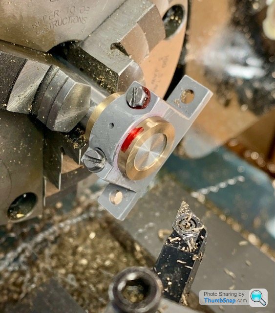
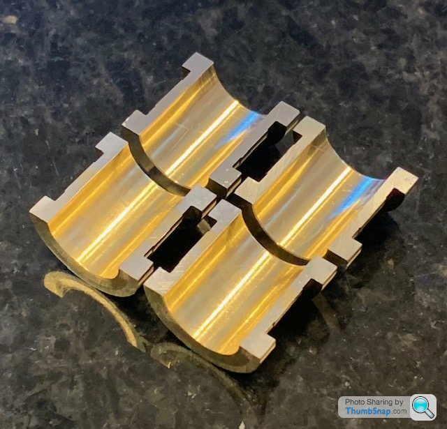
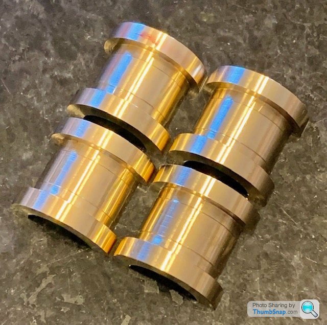
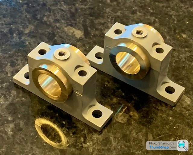
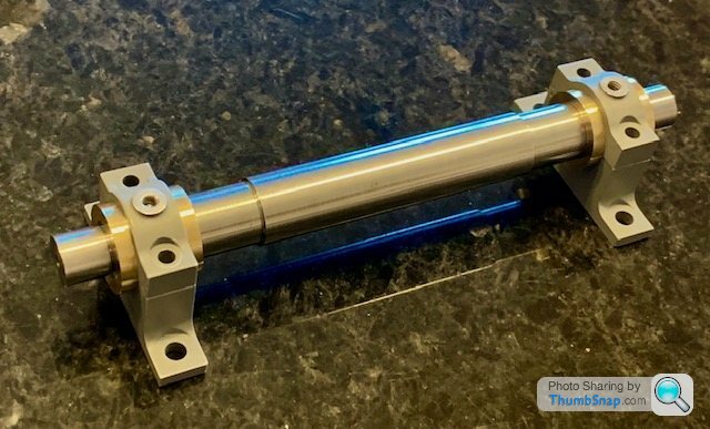
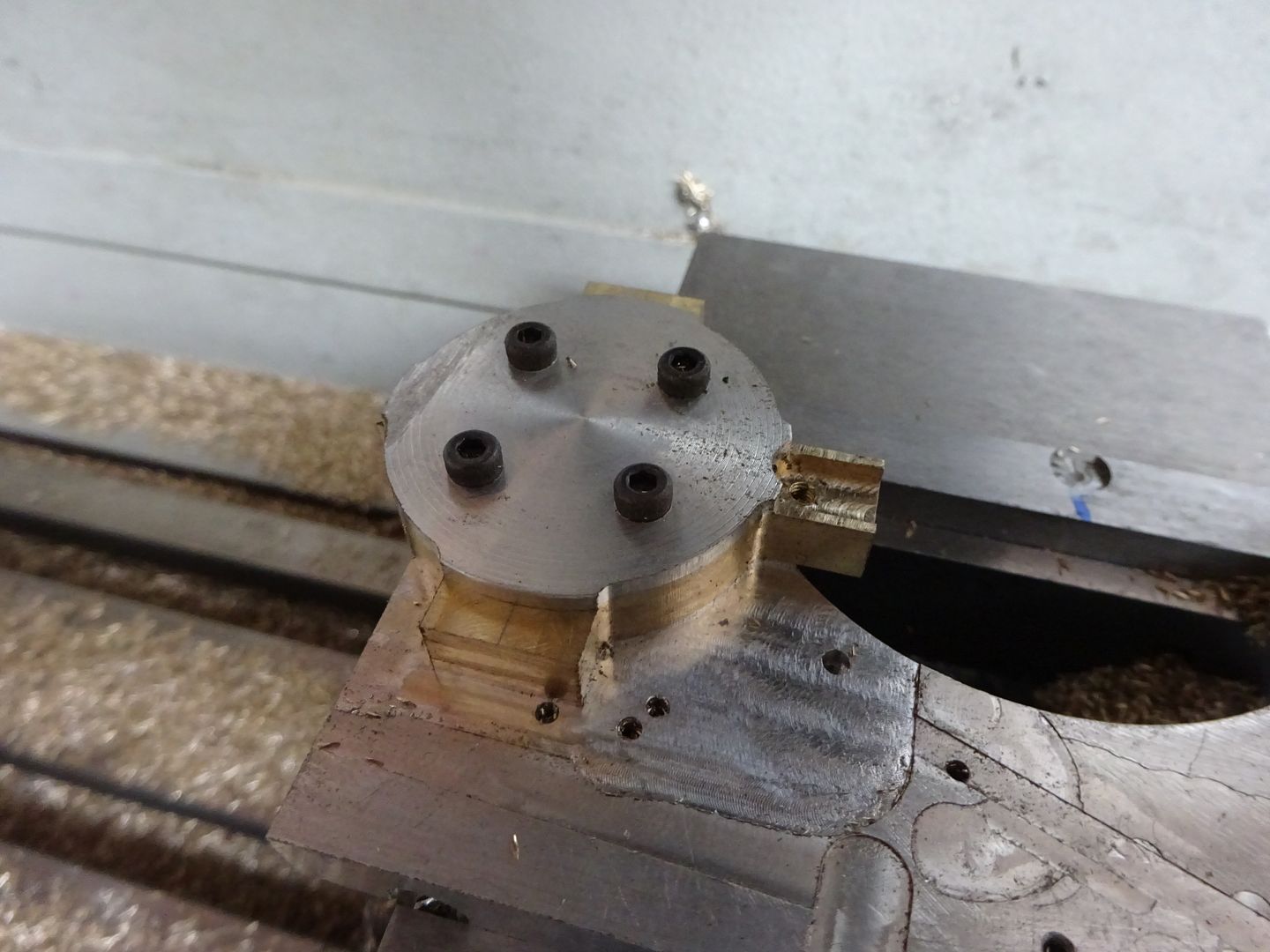
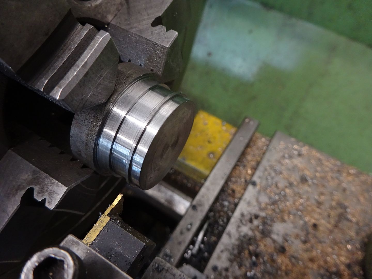
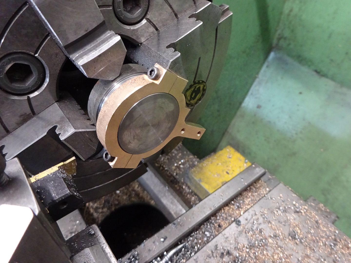
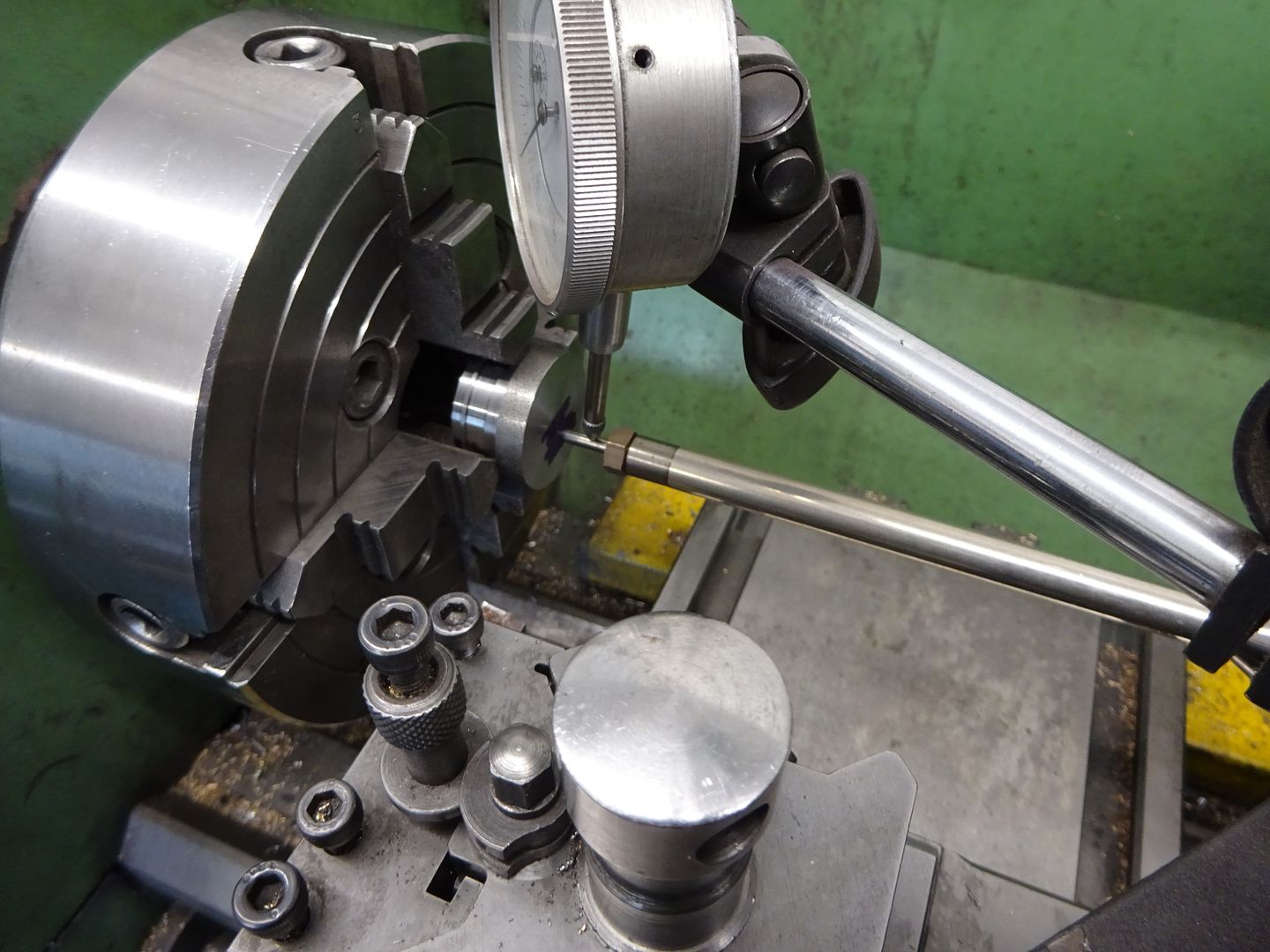
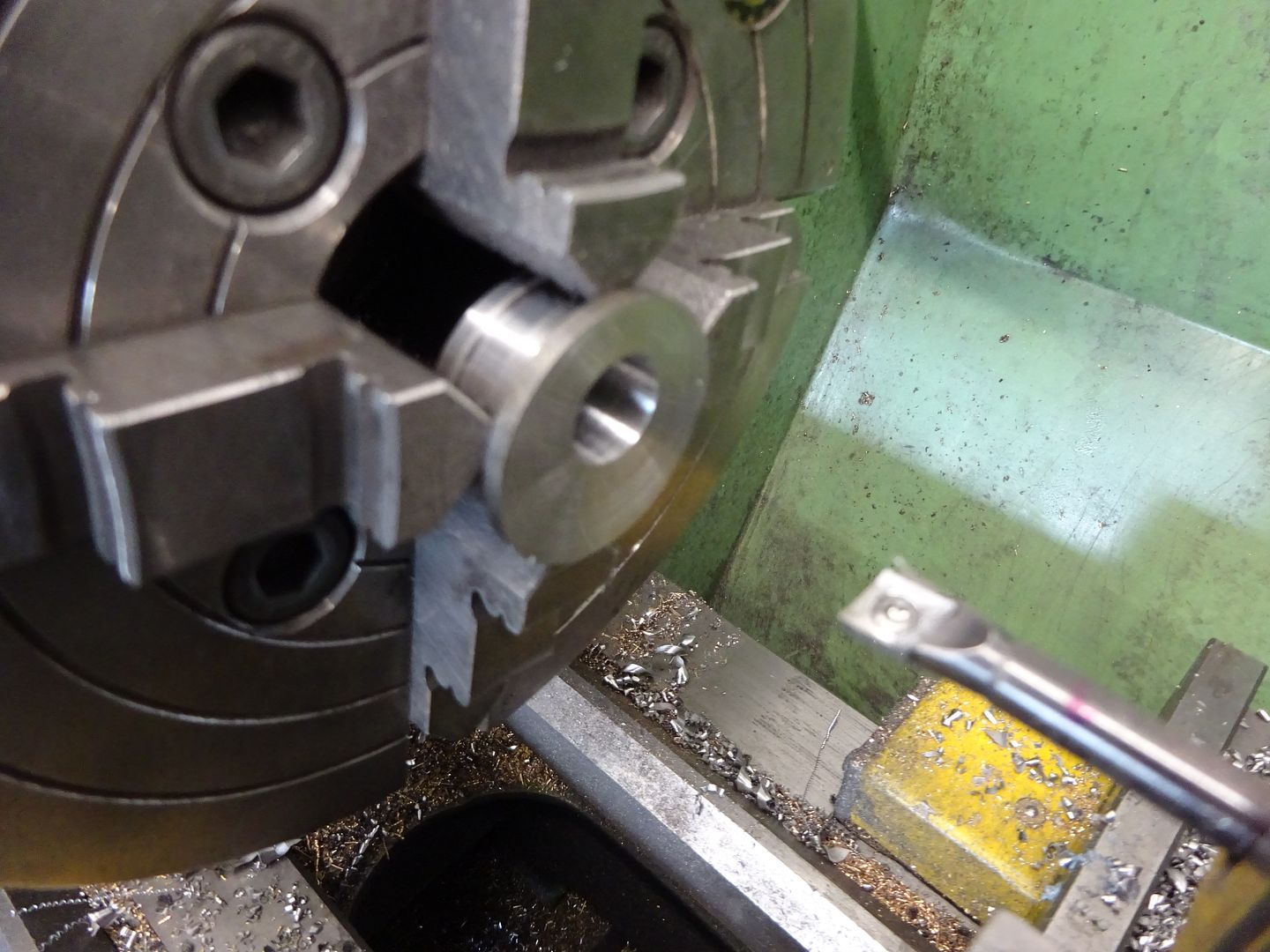
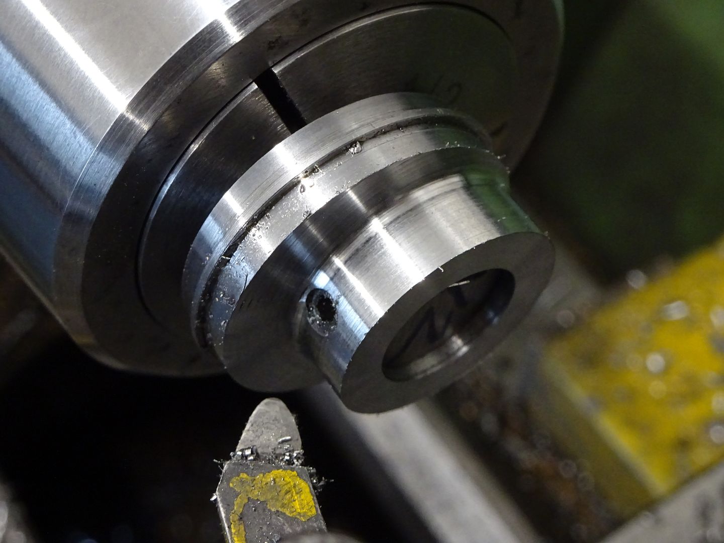
1602 forum posts | Got the other bearing made this afternoon. It was easier the second time around. I incremented the tool until it was the right fit, but this time I used the top slide dial to maintain a constant width side-to-side. I should have done that before, but I find that if I've been away from the workshop, it takes a while to get back into thinking things through properly. I also opted to make the flanges oversize in terms of width, and then faced to size on a mandrel. I did it this way becasue I found it very difficult to measure the flanges while grooving the slot and then parting off. It turned out that the first pedestal I made, which ended up scrap, was actually very useful in clamping the shells together while doing all this: So these are they:
The running fits seem fine, but I can't help thinking the surface finish could be better on the journals and shaft - it's pretty smooth in rotation, but if it's moved axially...I can tell it's been turned. Anyway, I think it's OK overall. |
| Hopper | 10/03/2023 21:26:59 |
 7881 forum posts 397 photos | Posted by Dr_GMJN on 10/03/2023 19:44:17:
The running fits seem fine, but I can't help thinking the surface finish could be better on the journals and shaft - it's pretty smooth in rotation, but if it's moved axially...I can tell it's been turned. Anyway, I think it's OK overall. If you want smoother on future jobs, try reaming the holes in the bearings for a smoother finish and use emery cloth to get the final smooth finish on the shaft. This gives you very fine control over the final shaft size for clearance too. |
| Dr_GMJN | 10/03/2023 22:34:08 |
1602 forum posts | Posted by Hopper on 10/03/2023 21:26:59:
Posted by Dr_GMJN on 10/03/2023 19:44:17:
The running fits seem fine, but I can't help thinking the surface finish could be better on the journals and shaft - it's pretty smooth in rotation, but if it's moved axially...I can tell it's been turned. Anyway, I think it's OK overall. If you want smoother on future jobs, try reaming the holes in the bearings for a smoother finish and use emery cloth to get the final smooth finish on the shaft. This gives you very fine control over the final shaft size for clearance too. Thanks Hopper. I don't have a 1/2" reamer, so the advice was to bore them instead. That worked OK. I did use wet and dry with some metal polish on the shaft bearings when I made the shaft. To be fair they're probably absolutely fine. It would just be nice to look at them and see a mirror finish is I guess where I'm at. |
| Hopper | 10/03/2023 23:16:33 |
7881 forum posts 397 photos | I've had good luck buying used machine reamers off eBay, old UK and Australian made ones. And if you can work in metric, whole sets of new Chinese "chucking reamers" are available amazingly cheaply and seem to work well enough for the home workshop. Well worth building up a collection. Or you can use a redneck hone for finishing bores. A length of wooden dowel with a hacksaw slot in the end with a strip of emery paper wrapped around it, fed by hand into the hole as it is spun in the lathe. Or held in a pistol drill and used like a brake cylinder hone. Sounds bodgy but works quite well. I am sure your bearings will work fine as is though. They look pretty nice in the pics, and pics tend to make such things look worse rather than better. Edited By Hopper on 10/03/2023 23:17:35 |
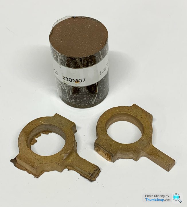
| Dr_GMJN | 12/03/2023 18:26:28 |
1602 forum posts | I'll try the eccentrics next. I've got the castings, and I think the bar is what I got for the sheaves: |
| JasonB | 12/03/2023 18:52:02 |
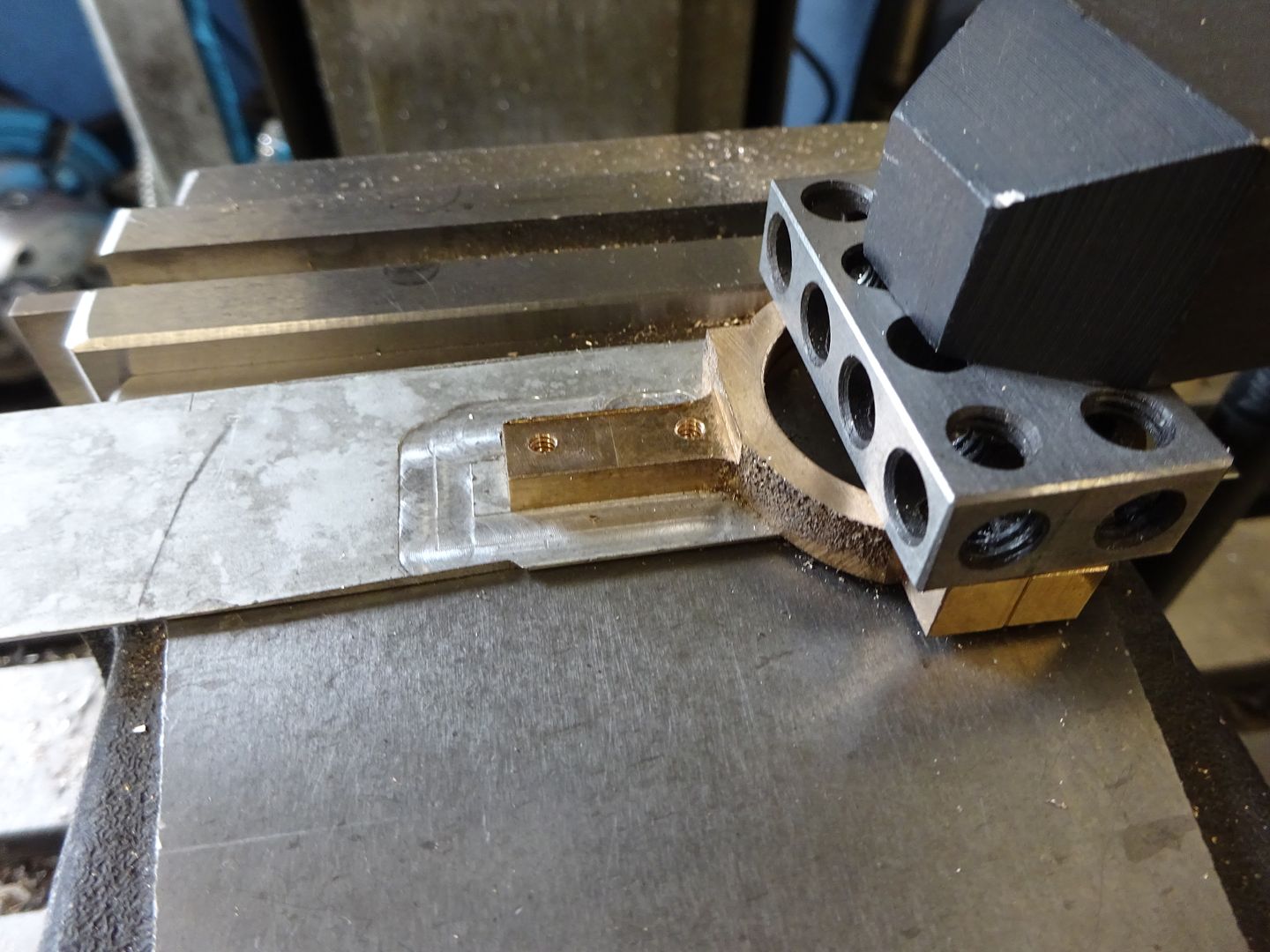
25215 forum posts 3105 photos 1 articles | I was saving these pics from when I did the Victoria for a rainy day but may as well post them now though the rain may be coming. looks like I first just held it roughly in teh 3-jaw to clean up one face then would have flipped it over and using some parellels faced the other sid eto bring it down to final width
Held in the mill vice mill the edges to width, mill the fixing surface flat,
drill tapping right through, clearance half way and tap
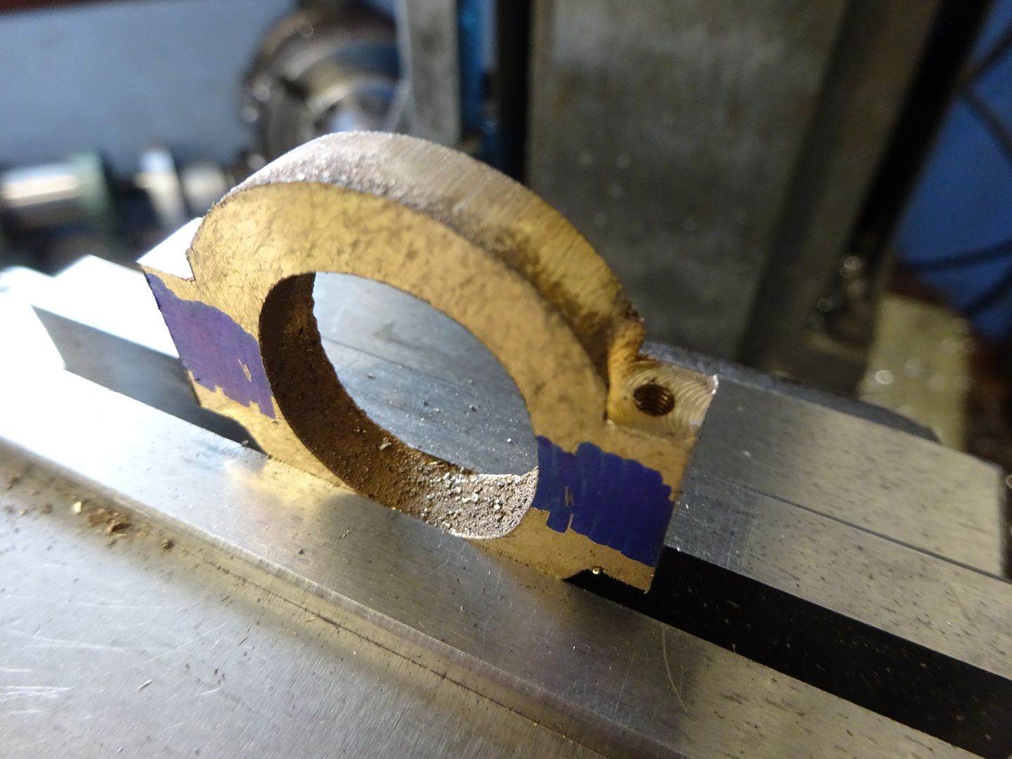
Saw in half then mill the sawn face still in the vice to clean it up
Mill the other face to clean up, two packers under the milled bolting faces will hold it level.
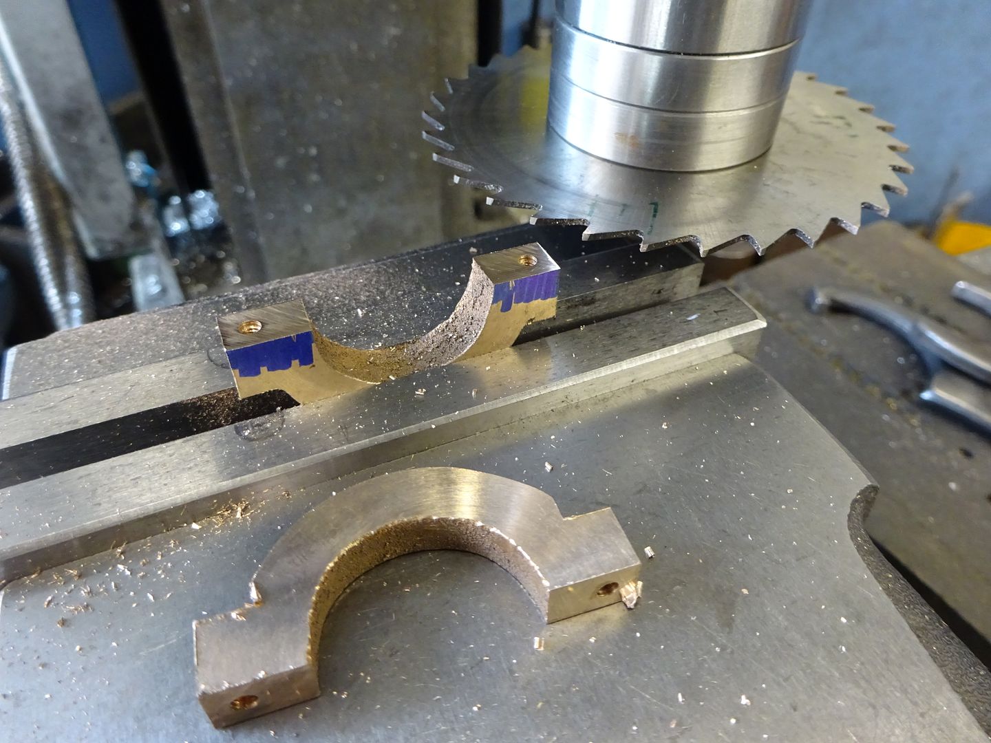
Screw together, hot glue a bit of scrap to the face and mark ctr position - can be done with edge finder & dro if you want
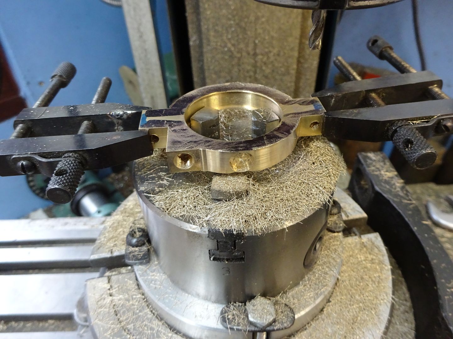
LIGHTLY holding in the 4-jaw so as not to distort the casting set your marked ctr to run true, parallels behind again then pop off the hot glue and bore.
With a suitable tool of known width and top slide set parallel to lathe axis touch off on front of work and zero dials. move tool in 1/2 its thickness plus half strap thickness and cut your groove it can be a bit deeper than the dimension
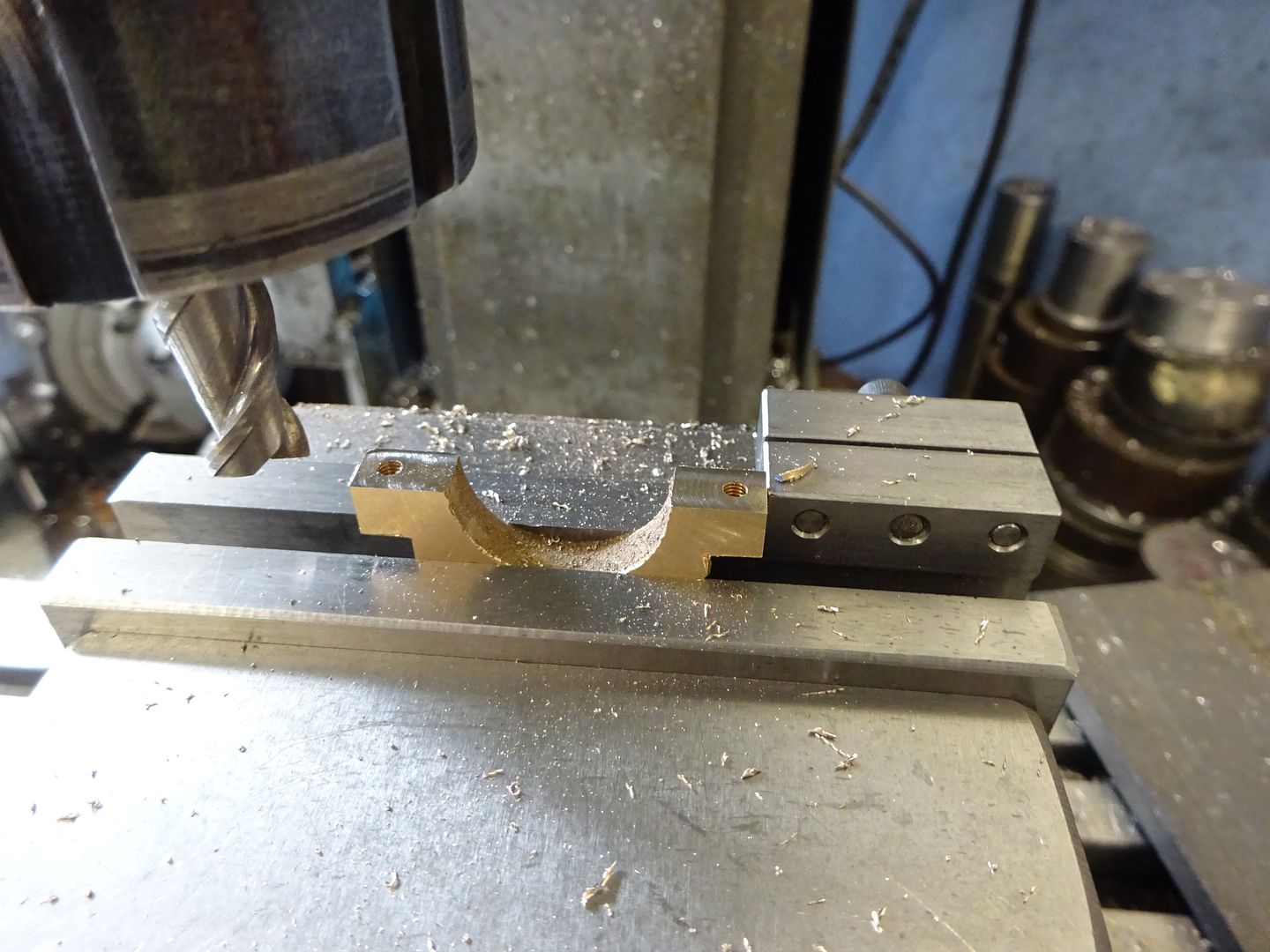
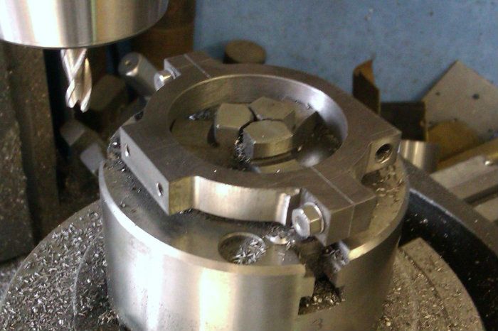
Mill the rod lug flat and drill
Make a top hat bush to clamp the strap down and mill the outside curves (different strap) you may need to file close to the screws.
|
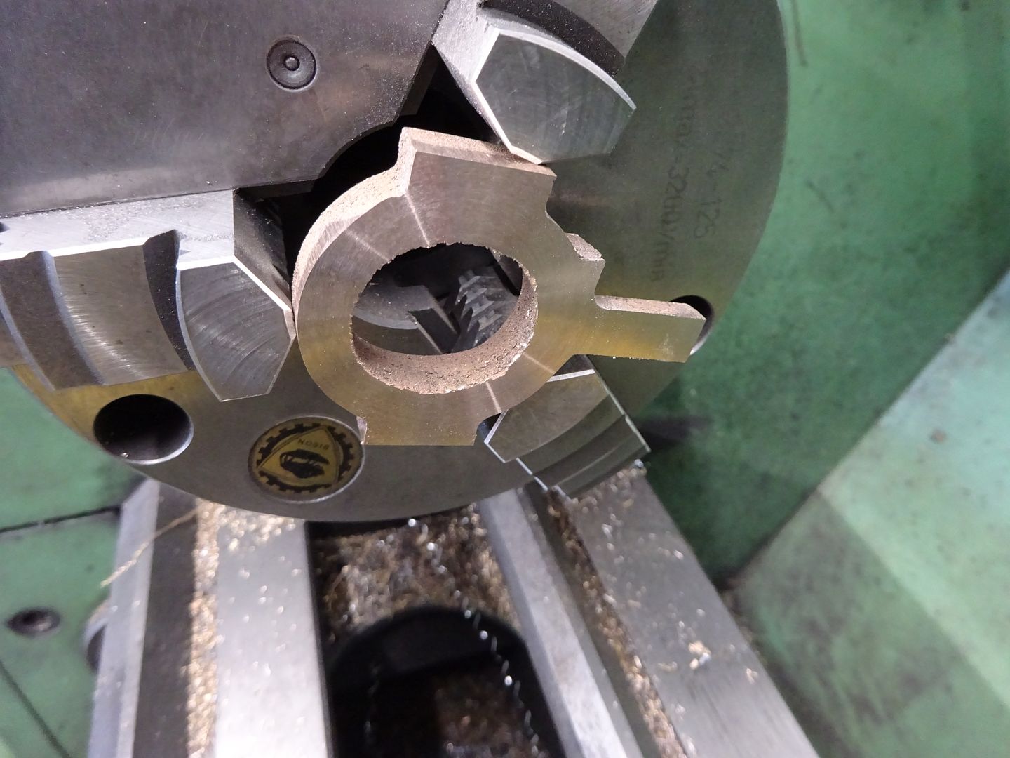
| JasonB | 12/03/2023 19:19:15 |
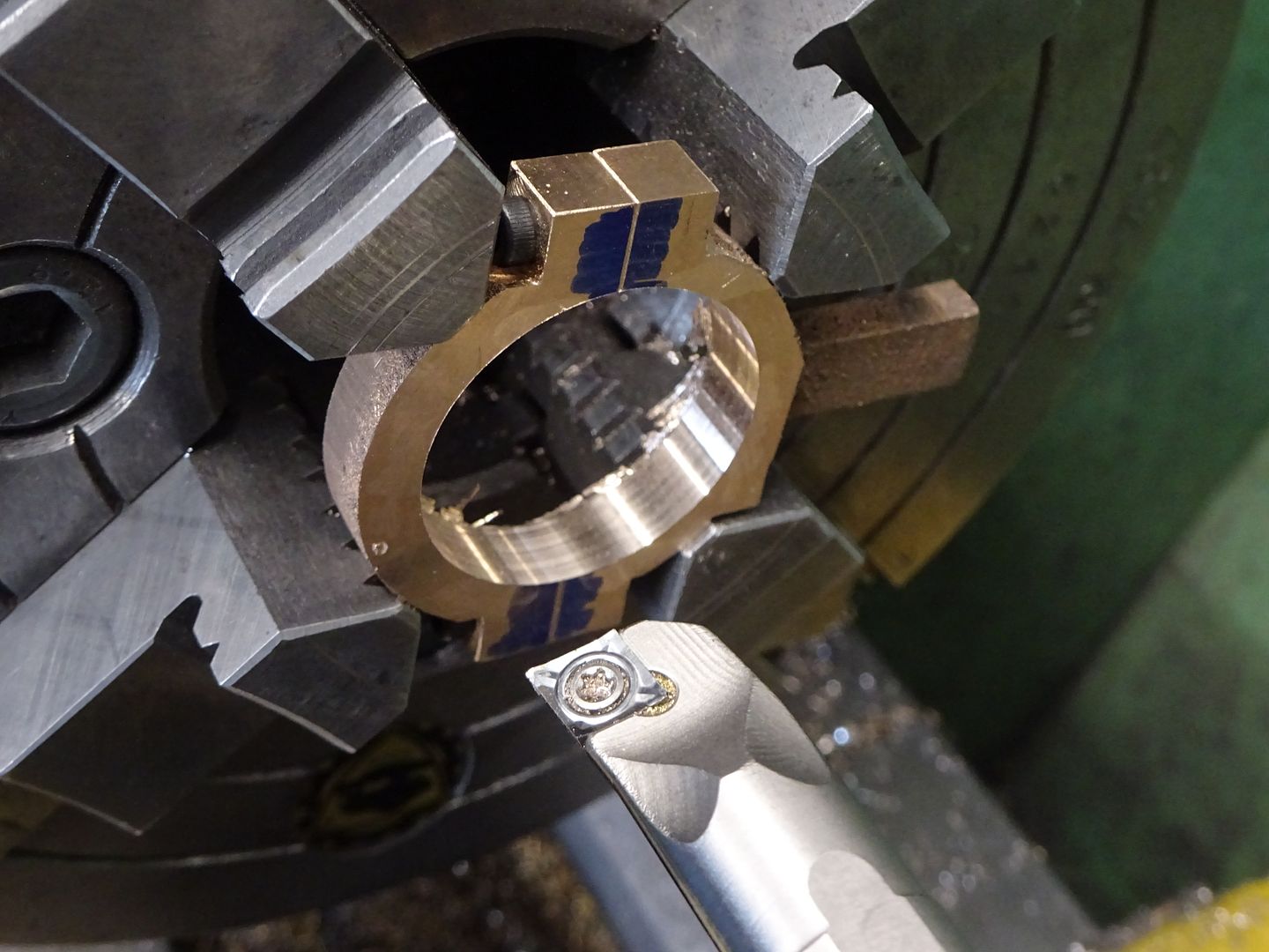
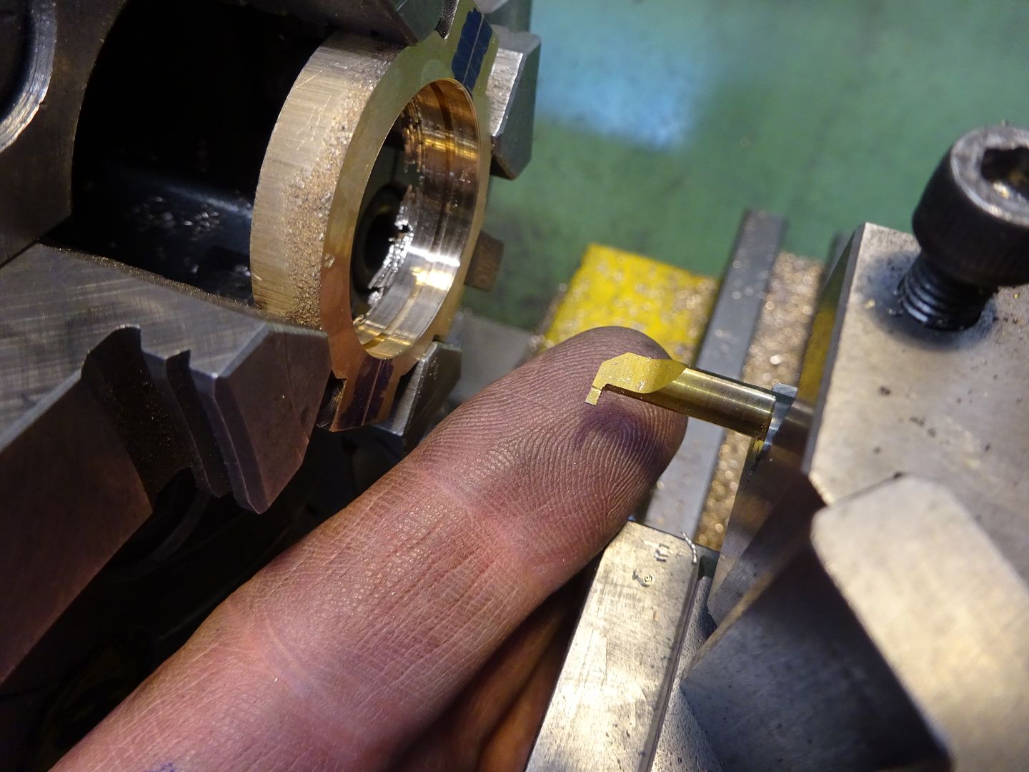
25215 forum posts 3105 photos 1 articles | I've never done an eccentric with the separate groove and loose ring like TC shows, this is how I did the victoria one to Stuart's drawing where it is all one piece Face your stock and turn down to a few thou over size for about 1/8" longer than the required strap width allowing for the short raised boss too. Turn down to final diameter enough to be beyond the ridge. Thenn use aparting tool first plunging and then moving side to side to bring the areas either side of the ridge to diameter
Use the strap to gauge diameter, having the groove a bit deeper ensures you are testing fir on the running surfaces
Saw off from parent bar with enough for the longer boss, reverse in chuck and skim the face (3-jaw will do) now mark a horizontal ctr line on work, rotate chuck 90degrees and mark another line 1/8" higher
Punch that mark and then holding I the 4-jaw set the mark to run true, parallels behind work or if your stock is large like mine push that against jaws
Drill and bore to a close fit on your crankshaft before moving to the mil and drilling & tapping for grub screw(s)
Put a stub of round bar in chuck or collet and using teh grub screw fit eccentric to that so you can then turn the bosses with a round nosed tool.
|
| Dr_GMJN | 12/03/2023 21:02:29 |
1602 forum posts | Thanks very much Jason. Makes sense. I guess you machined the outer strap profile in the CNC machine? I'd just put mine in the R/T. Also, rather than mark out the eccentric offset with a height gauge, I guess I could do it in the mill, and centre drill the offset hole? I'll not bother with the separate ring - doesn't seem any point in not doing it like you suggest. I just checked, and my slitting saw is not quite big enough to go through both sides of the strap when central in the vice - the end nut hits the side of the vice. I guess I could slit saw as much as I can, then finish the last mm or so with the hacksaw? Then mill all faces. |
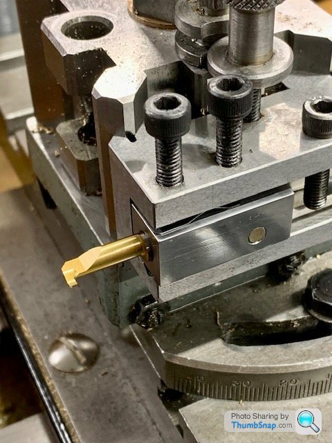
| Dr_GMJN | 12/03/2023 21:44:24 |
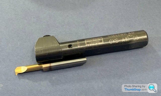
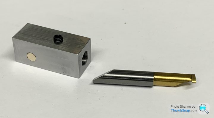
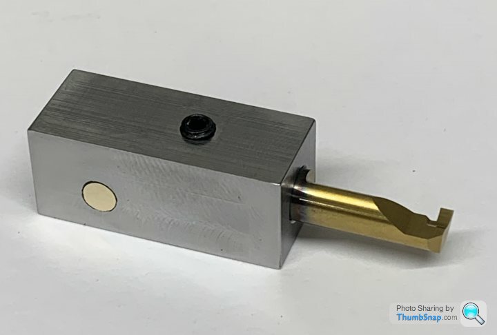
1602 forum posts | I was given this Sandvik internal bar holder, but I've only got a couple of internal threading tools (which I've never needed): |
| Baz | 12/03/2023 22:07:22 |
| 1033 forum posts 2 photos | Jason can you tell me where you got your lovely internal grooving tool from? |
| JasonB | 13/03/2023 07:03:58 |
25215 forum posts 3105 photos 1 articles | Grooving inserts came free from another member but look to be the same as the Sandvik one shown by Doc The outer profiling in that image was indeed on the CNC as I was making it from scratch and did not have a photo of the casting being done. but you can mount in a similar way on the R/T or if you have a small chuck like this
Yes you can finish the cut by hand if needed and mark out on the mill
|
| Dr_GMJN | 13/03/2023 12:58:18 |
1602 forum posts | Those inserts are quite expensive at about £25 each, plus a 6mm holder (mine is 5mm) is about £70. I wonder if a holder made from square bar, drilled out with a grub screw would do for this? a L/H insert (threading type) might also be useful for machining the rope grooves in the flywheel? |
| JasonB | 13/03/2023 13:05:10 |
25215 forum posts 3105 photos 1 articles | I just hold mine in a bit of bar with a grub screw. You can also just grind the end of an old ctr drill or milling cutter like a little parting tool and hold that in a bar drilled at right angles to tale it and a grub screw in the end to retain it. I would just set your DCMT holder at an angle and use that for the rope grooves, it will be a lot more rigid. |
| Dr_GMJN | 13/03/2023 13:32:21 |
1602 forum posts | Posted by JasonB on 13/03/2023 13:05:10:
I just hold mine in a bit of bar with a grub screw. You can also just grind the end of an old ctr drill or milling cutter like a little parting tool and hold that in a bar drilled at right angles to tale it and a grub screw in the end to retain it. I would just set your DCMT holder at an angle and use that for the rope grooves, it will be a lot more rigid. Yes I might just use a bar then. If I was going to grind a drill or something, I'd just use an old HSS boring bar and grind that. I think the issue I will have when machining the O/D of the flywheel is that the ML7 doesn't really have the capacity to hold a tool rigidly at that diameter. I would have to check that though. |
| Dr_GMJN | 16/03/2023 17:40:16 |
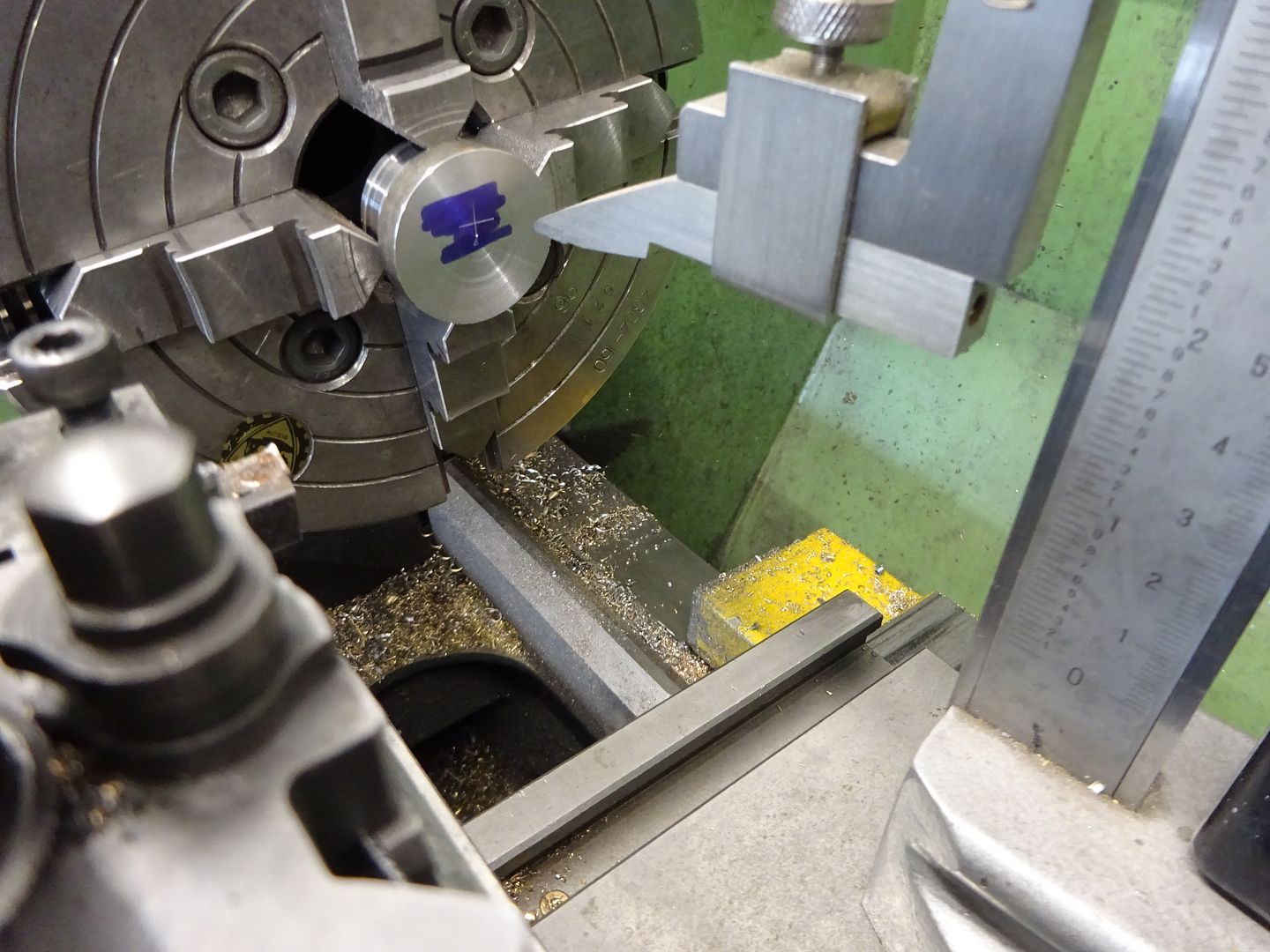
1602 forum posts | Looking at the strap castings - I’m hoping it’s right that they’re not handed? So presumably a slight offset is required on the eccentric arms and/or operating levers to compensate? |
| JasonB | 16/03/2023 18:35:39 |
25215 forum posts 3105 photos 1 articles | Probably easiest to make the straps and rods the same and then sort out the slightly different offsets when you come to make the rocker arms and pin, a slightly longer pin on one engine would be the neatest way to do it. Not sure what your silver soldering is like but you may want to consider deviating from the brazed on fork to the ends of the rods and do them just as flat strips with a hole in the end and rounded over. You can then make the rocker arm 1/4" thick and put a slot in the end for the eccentric rod to go into. I've done that on the Victoria, Real and James Coombes as I really don't like the Stuart bolted together forked end to the eccentric rods
|
| Dr_GMJN | 16/03/2023 22:19:06 |
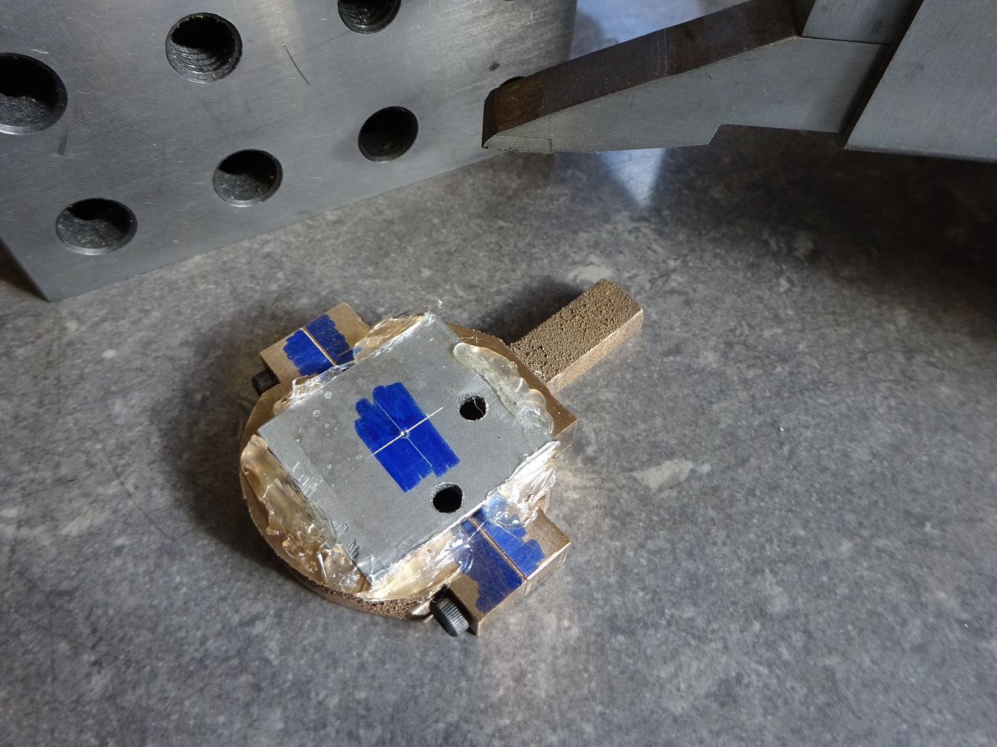
1602 forum posts | OK thanks Jason. Yes, extending the shaft I think is the best option - that's what I meant by an offset on the operating lever. I think the original plans call for the crank in the bar to be screwed together? (I've not got the plans to hand right now). BTW I don't have any silver soldering kit yet. Also, you previously mentioned D&Ting one side of the eccentric straps - presumably this is just temporary for profiling, and a bolt and locknut would be used for the final assembly? I thought I read somewhere that studs weren't used in steam engine castings (not sure why). I guess having two square blocks either side of the joint suggests a bolt and nut fixing was the intention? I got a grooving tool from Cutwel, and made a holder this evening. I added a brass pin to stop it rotating (I assume that's what the chamfer is for), and a grub screw for axial location: I used on off-cut from the steel I boght for the connecting rods. It seemed to mill quite nicely for once, so I guess that bodes well for when I get on to those. |


Please login to post a reply.
Magazine Locator
Want the latest issue of Model Engineer or Model Engineers' Workshop? Use our magazine locator links to find your nearest stockist!
Sign up to our Newsletter
Sign up to our newsletter and get a free digital issue.
You can unsubscribe at anytime. View our privacy policy at www.mortons.co.uk/privacy
Latest Forum Posts
- hemingway ball turner
04/07/2025 14:40:26 - *Oct 2023: FORUM MIGRATION TIMELINE*
05/10/2023 07:57:11 - Making ER11 collet chuck
05/10/2023 07:56:24 - What did you do today? 2023
05/10/2023 07:25:01 - Orrery
05/10/2023 06:00:41 - Wera hand-tools
05/10/2023 05:47:07 - New member
05/10/2023 04:40:11 - Problems with external pot on at1 vfd
05/10/2023 00:06:32 - Drain plug
04/10/2023 23:36:17 - digi phase converter for 10 machines.....
04/10/2023 23:13:48 - More Latest Posts...
- View All Topics
Support Our Partners


Shopping Partners
Subscription Offer

Latest "For Sale" Ads
- Reeves** - Rebuilt Royal Scot by Martin Evans
by John Broughton
£300.00 - BRITANNIA 5" GAUGE James Perrier
by Jon Seabright 1
£2,500.00 - Drill Grinder - for restoration
by Nigel Graham 2
£0.00 - WARCO WM18 MILLING MACHINE
by Alex Chudley
£1,200.00 - MYFORD SUPER 7 LATHE
by Alex Chudley
£2,000.00 - More "For Sale" Ads...
Latest "Wanted" Ads
- D1-3 backplate
by Michael Horley
Price Not Specified - fixed steady for a Colchester bantam mark1 800
by George Jervis
Price Not Specified - lbsc pansy
by JACK SIDEBOTHAM
Price Not Specified - Pratt Burnerd multifit chuck key.
by Tim Riome
Price Not Specified - BANDSAW BLADE WELDER
by HUGH
Price Not Specified - More "Wanted" Ads...
Get In Touch!
Do you want to contact the Model Engineer and Model Engineers' Workshop team?
You can contact us by phone, mail or email about the magazines including becoming a contributor, submitting reader's letters or making queries about articles. You can also get in touch about this website, advertising or other general issues.
Click THIS LINK for full contact details.
For subscription issues please see THIS LINK.
Digital Back Issues


Donate

 Register
 Log-in
Model Engineer Magazine
- Percival Marshall
- M.E. History
- LittleLEC
- M.E. Clock

ME Workshop
- An Adcock
- & Shipley
- Horizontal
- Mill

Subscribe Now
- Great savings
- Delivered to your door

Pre-order your copy!
- Delivered to your doorstep!
- Free UK delivery!
All Forum Topics > Work In Progress and completed items > Stuart Twin Victoria (Princess Royal) Mill Engine