Forum sponsored by:

Stuart Twin Victoria (Princess Royal) Mill Engine
| Dr_GMJN | 09/03/2023 07:43:11 |
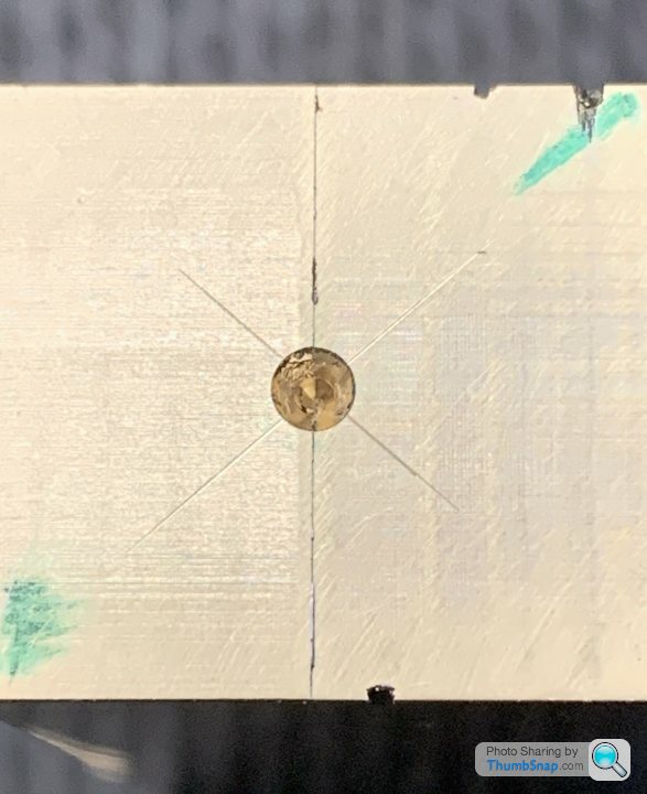
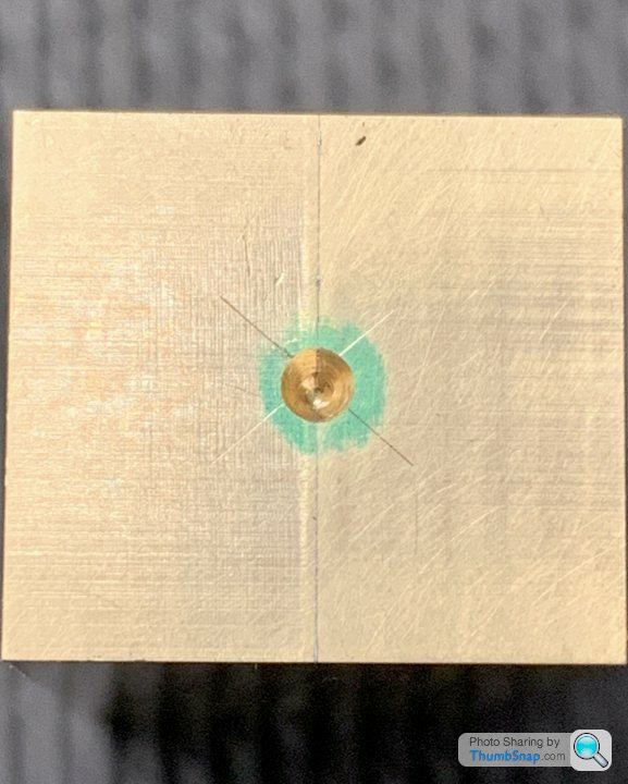
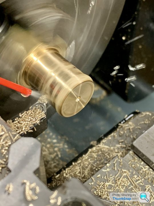
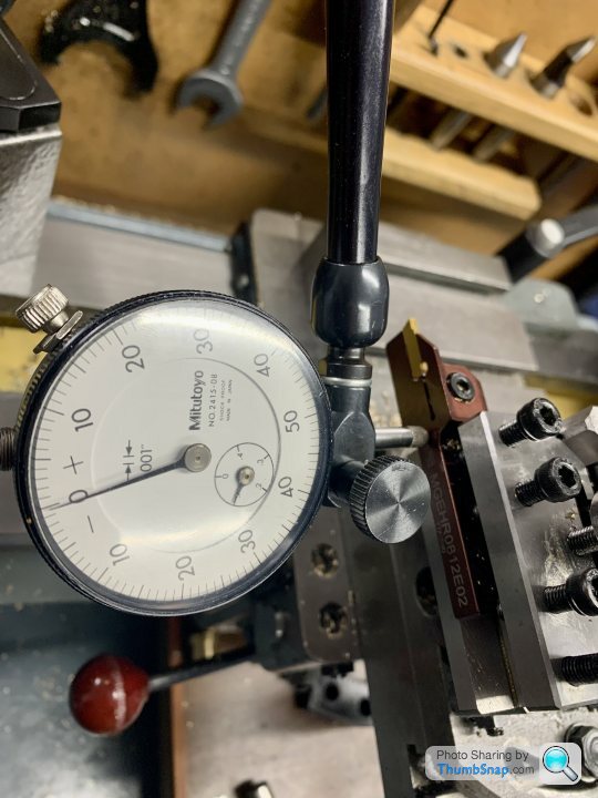
 1602 forum posts | Thanks guys. Yes, looks like one of the drillings isn’t on the line. It’s odd because I used an edge finder to get the centre for drilling (the thicknesses of the bars was identical) and then a dti on a centering rod in the lathe, plus checked the faces with the dti as a double-check, and all was good. Anyway, well spotted.
|
| Ramon Wilson | 09/03/2023 07:57:37 |
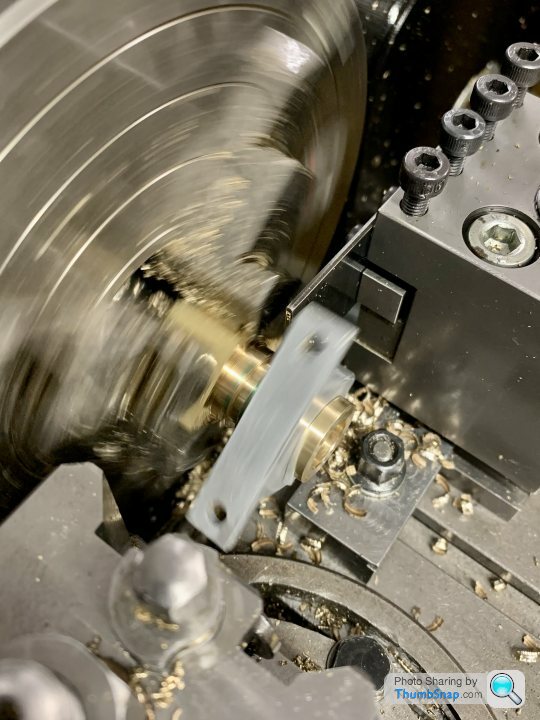
 1655 forum posts 617 photos | Some thoughts The over hang is too long The centre, however gently applied, will act as a wedge applying a separating pressure on the weakest point - the soldered faces. The act of turning the groove will apply more pressure on the joint too. Once the OD is turned the 'clamp' of the bearing pedestal needs to be tight otherwise the drilling will apply more pressure to the now very narrow soldered faces Parting off is likely to be a nightmare. with the 'clamp' in place.
Some further thoughts Cut off enough to make one bearing (twice) Hold in mill vise with soldered faces clamped, face, drill and bore. If no boring head drill to within .5mm on diameter and return to lathe in four jaw. Bore to size. Much easier to centralise part on mill than four jaw with the outside surfaces known to be parallel to the split line. Make simple mandrel with very slight taper that bearing pushes on and very gently face each end true to bore. Make parallel mandrel and clamp washer and clamp firmly on mandrel to turn OD to finish size. If the soldering was efficient the bearing can then be held on an expanding mandrel to turn to finish width and any steps etc possibly required on each end. As always, your choice of course, but having been down the route before without success I'd seriously not be thinking of repeating the exercise.The above will give the certainty of accuracy, with the least stress on the split line but then - what would I know Good luck with it Doc
Just seen your last post. Easily rectified in the mill op Edited By Ramon Wilson on 09/03/2023 08:00:03 |
| Dr_GMJN | 09/03/2023 08:13:18 |
1602 forum posts | Hopper - I made the previous two without much problem. IIRC the solder failed, but it was close to the jaws so turning the OD wasn’t an issue. The only problem we’re the tapered walls with the old parting tool. If I shorten the bar and do each bearing separately, the chuck would approximate a milling vice, and I’d also know the OD and ID were concentric. BTW Jason, the hole in the chuck won’t allow the bar to pass through. |
| JasonB | 09/03/2023 09:21:57 |
 25215 forum posts 3105 photos 1 articles | Ah yes looking back you have a threaded body chuck so spindle nose is probably in the way though would roughing the ends down to round first then allow it to be moved further in? Using the Pedestal and cap as a clamp was just a belt and braces suggestion while boring in case the joint was suspect, could be removed before parting and I do tend to have a gap between cap and body so a tight fit would result. Though if it is a suspect joint a tapered mandrel could also pop it apart. Take your pick. Not sure if you have collets or if they would go large enough and how true they run but that is another way to hold things, turn OD and waist, part/saw off and face to length then hold in a collet to bore which holds the two halves together. |
| Dr_GMJN | 09/03/2023 12:18:03 |
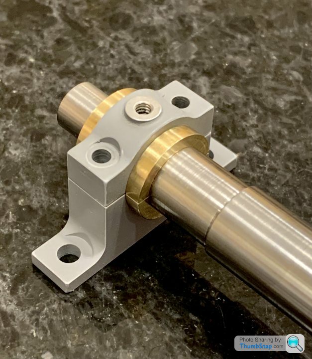
1602 forum posts | Thanks all. Firstly, I was puzzled by the off-centre drillings, so I took the part out of the chuck and checked again. I think they are fine; it must have been the angle the photo was taken at: I don’t have a boring head for the mill, but even if drilling almost to size, as mentioned, wouldn’t subsequent use of a tight fitting or expanding mandrel in the lathe then defeat the objective of retaining some radial clamping? I’d have thought using the 4-jaw for the entire process would be less risky in terms of the part coming apart? |
| Ramon Wilson | 09/03/2023 13:05:46 |
1655 forum posts 617 photos | Not saying that radial clamping is wrong - just, in my opinion, unnecessary and certainly unwieldy using the bearing pedestal. Nothing wrong with using a four jaw either but on a mandrel all bearings are identical to the bore with nothing more required to achieve accuracy one to one than setting it in place on the mandrel. It's just a different way of going about it without the possibility of creating slight inaccuracies that will manifest them selves on assembly. Besides there is no way of 'knowing' if a part in a four jaw is axial especially if the chuck is old - it's a facility I try to avoid if there is other means. Though I use it a fair bit in other ways I have never used it to make identical bearings because of that possibility and to me its always easier to bring the outside to a bore - on a mandrel - than the other way. I've made a fair number of bearings from quite small 3/16 diam to the ones on the Corliss quite large by comparison in the method suggested. Only had one part in two by machining on the mill as the reamer went in due to the the faces not clamped between the vise jaws and one split on an expanding mandrel due to a poor solder joint. There's a fair bit of work in achieving the fits necessary in bearings to ensure good alignment but as already said the choice is down to the individual. |
| Dr_GMJN | 09/03/2023 13:35:03 |
1602 forum posts | Thanks Ramon. Looking back over the discussions on the shaft etc. before I had a break, I honestly can’t remember all the suggestions and pros and cons of shaft first/bearing first. The thread got rather disjointed with me going from one job to another for some reason. Anyway, somehow I ended up with shaft first. I’m happy I can bore the bearings to be a tight running fit on the shaft, ready for lapping when everything is in place on the beds. But…splitting the bearings and removing the solder will inevitably make them tighter on the shaft when re-fitted, and, effectively the mating faces will be slightly higher in the pedestals and caps. I guess I will need to flat the housing faces to suit, and as IIRC Jason and/or yourself said - use the bearing cap lock nuts to adjust? I think that’s the theory, and really the only way to maintain a true cylindrical journal on assembly (even if it’s not a complete cylinder)?
|
| Ramon Wilson | 09/03/2023 14:20:09 |
1655 forum posts 617 photos | I advocated the 'bearings first' method Doc simply because it is much easier to try a pre-made bearing on the shaft than to use the shaft as a plug gauge with it's attendant risk of wringing the part in the chuck due to it's length. The very method of soldering the parts together introduces the situation you refer too. However, the solder thickness should be quite thin but does always leave a residue on breaking apart. lapping the solder residue away on something flat will increase the tightness of the bearing as you say. Though miniscule there will always be a slight 'out of circular hole' as a result so that's when a little scraping or fine removal with wet and dry on a smaller diameter shaft comes in - just in the bottoms of the bearing shells and not on the sides. If you do this right you should not have to lap the bearings to the shaft on assembly. This is why I suggested to you to make the base and build the engine up as you go - dealing with any such misalignment in turn before moving on to the next addition.
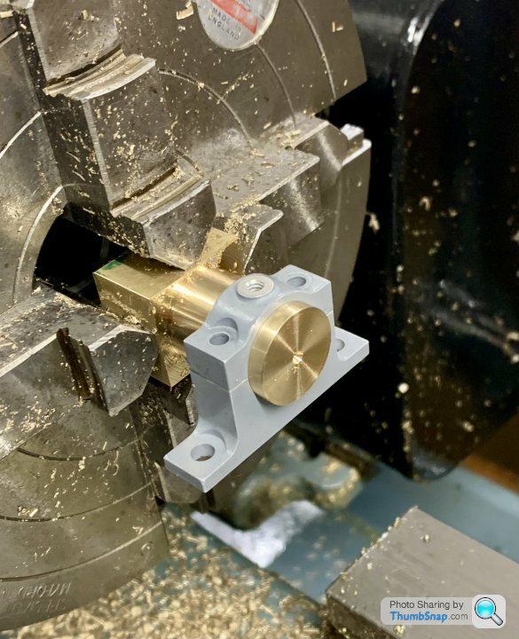
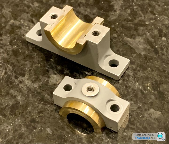
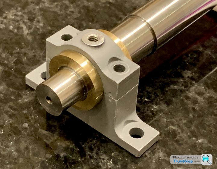
These three bearings were done exactly as described and not line bored in situ. The shaft is a good fit laterally and the bearing shell tops slightly tweaked to allow the bearing caps to pull up without the shaft binding - it runs very freely in fact.
BTW you may note that the bearings are in place to act as 'masks' whilst painting the base. Once removed the paint was cleaned off the bearing shells with a soak in cellulose thinner - perfect fit without having to make allowances for paint
|
| JasonB | 09/03/2023 14:22:11 |
25215 forum posts 3105 photos 1 articles | Many a bearing cap has a good gap between it and the lower housing so you often see nuts and locknuts on the studs as they are not fully tightened down but just enough to allow the shaft to rotate freely in the bearings. From that it can be deduced that the bearings themselves to not have to be closed right up so the split faces touch. Some engines will have shims between cap and housing but less so or had shim placed before the bearings were bored.. Take a look through that old book pdf and you will see the gaps and on the larger engines there was also facility to close up the bearings front to back as they wore or were rescraped.
|
| Dr_GMJN | 09/03/2023 15:46:01 |
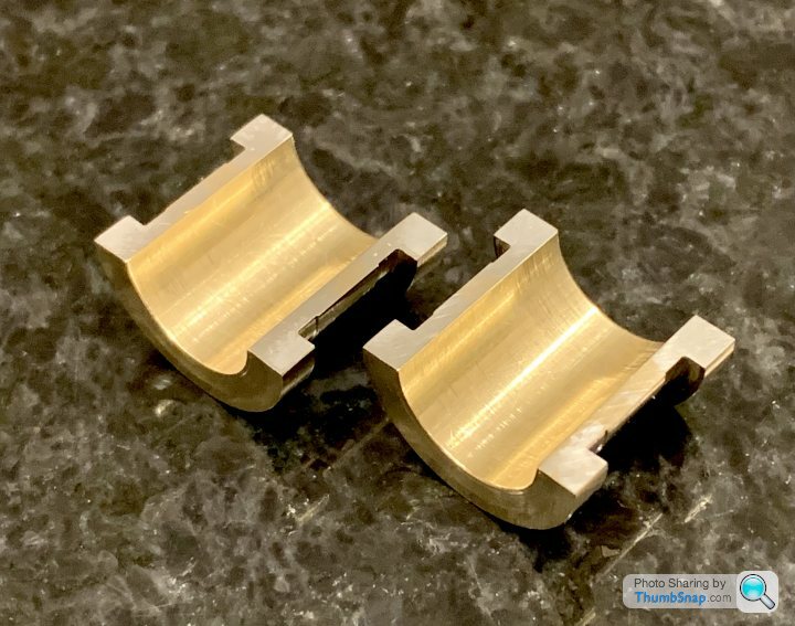
1602 forum posts | Ramon, Jason, OK so as I see it, if I bore the bearings to be a good fit (maybe a little tighter than optimum for now), then even after separation, the bores will be cylindrical (but individually not full half cylinders), and obviously exactly the same diameter they were before separation, and will therefore still match the shaft. So on re-assembly after removing the solder, assuming the bearing was an accurate fit in the housing, no further work should be required, since the only change would be a gap between the bearing faces - the cap-pedestal gap would still be zero on tightening? If the bearings were to wear, then the cap faces could be thinned, allowing the bearings to be tightened? But, in full-size practice, the caps would be thinned by default and shimmed back to size initially, since this would simplify maintenance (no machining, just shimming)? This would make sense.
|
| JasonB | 09/03/2023 15:53:09 |
25215 forum posts 3105 photos 1 articles | Well if they are bored tighter than optimum they will still be tight on assembly |
| Dr_GMJN | 09/03/2023 16:21:26 |
1602 forum posts | Posted by JasonB on 09/03/2023 15:53:09:
Well if they are bored tighter than optimum they will still be tight on assembly
|
| Ramon Wilson | 09/03/2023 16:41:11 |
1655 forum posts 617 photos | Yes - Jason Is spot on here Doc, the cap just holds the bearings in place and should not distort them - if you think about it if the cap is fully tightened down to the housing/pedestal and the shaft is free to rotate then the shell must have a gap - the slightest distortion will tighten things up considerably - any wear cannot be taken up unless the cap is further reworked. The caps are usually relieved each side of the bearing cavity to allow this. 'Setting' the locknuts will soon reveal just how little movement is required between locked tight and running fits. IE the clamping pressure is entirely set by the bearing cap bolts. I thought you were aware of this situation.
|
| Ramon Wilson | 09/03/2023 16:46:58 |
1655 forum posts 617 photos | Here you are this will explain it
The locknuts on top or bottom is entirely up to you |
| JasonB | 09/03/2023 17:06:58 |
25215 forum posts 3105 photos 1 articles | I think Ramon is the same as me regarding polishing an assembly until it runs smooth, You really should be making the parts to run correctly and if on assembly the shaft is tight in the bearing it is not an issue with the shaft or the hole in the bearing but something else causing it to be tight and that is what needs to be rectified. For the same reason I'm not of fan of "motoring" an model to get rid of tight spots, that is the practice of fixing it up to a motor and running for an hour or so to wear off the tightness. |
| Dr_GMJN | 09/03/2023 23:16:12 |
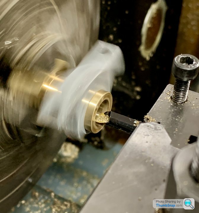
1602 forum posts | So, deep breath, and try again… |
| Ramon Wilson | 10/03/2023 07:59:08 |
1655 forum posts 617 photos | Good result Doc |
| Dr_GMJN | 10/03/2023 08:25:14 |
1602 forum posts | Posted by Ramon Wilson on 10/03/2023 07:59:08:
Good result Doc Thanks Ramon. I really did pick a good time to start again -3 forecast for this evening… I still need to drill the oil and anti-rotation holes. May have been discussed, but plan is to assemble, put in the mill and drill a 1mm hole through everything from the top (aligned with the existing oil hole in the cap). If the drill won’t reach the bottom I’ll have to remove the cap and then go through the bottom shell and housing with a drill appropriate for whatever brass or steel rod I can find. Then tap the rod into the housing with Loctite.
|
| Ramon Wilson | 10/03/2023 08:49:33 |
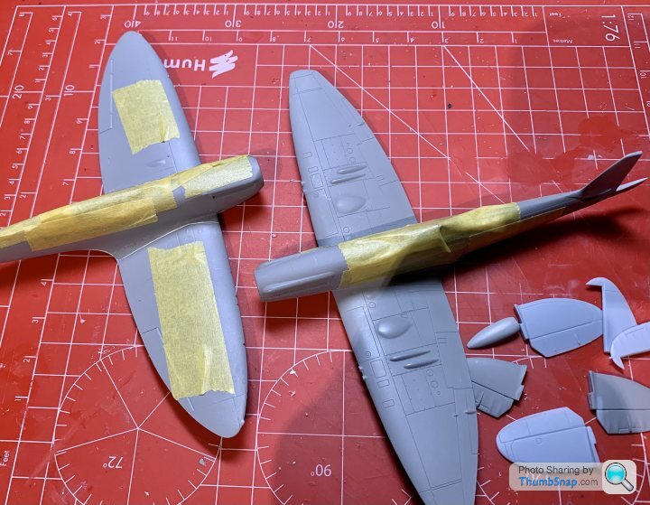
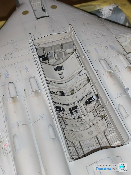
1655 forum posts 617 photos | Well I don't envy you there Doc - the one thing I can say is I do have a warm workshop to hibernate in. I guess that's as good a reason to 'hit the plastic' over the winter as any. Though not for the same reason I took a break from the marine engine for the same distraction and am just in the finishing throes of a 1/32 Phantom. Take care with that one mil drill tonight - 1.5 might be a bit safer? |
| Dr_GMJN | 10/03/2023 09:01:49 |
1602 forum posts | Yes, I’ll have to check what size hole is in the cap. It might be 1.5mm |
.jpg")


Please login to post a reply.
Magazine Locator
Want the latest issue of Model Engineer or Model Engineers' Workshop? Use our magazine locator links to find your nearest stockist!
Sign up to our Newsletter
Sign up to our newsletter and get a free digital issue.
You can unsubscribe at anytime. View our privacy policy at www.mortons.co.uk/privacy
Latest Forum Posts
- hemingway ball turner
04/07/2025 14:40:26 - *Oct 2023: FORUM MIGRATION TIMELINE*
05/10/2023 07:57:11 - Making ER11 collet chuck
05/10/2023 07:56:24 - What did you do today? 2023
05/10/2023 07:25:01 - Orrery
05/10/2023 06:00:41 - Wera hand-tools
05/10/2023 05:47:07 - New member
05/10/2023 04:40:11 - Problems with external pot on at1 vfd
05/10/2023 00:06:32 - Drain plug
04/10/2023 23:36:17 - digi phase converter for 10 machines.....
04/10/2023 23:13:48 - More Latest Posts...
- View All Topics
Support Our Partners


Shopping Partners
Subscription Offer

Latest "For Sale" Ads
- Reeves** - Rebuilt Royal Scot by Martin Evans
by John Broughton
£300.00 - BRITANNIA 5" GAUGE James Perrier
by Jon Seabright 1
£2,500.00 - Drill Grinder - for restoration
by Nigel Graham 2
£0.00 - WARCO WM18 MILLING MACHINE
by Alex Chudley
£1,200.00 - MYFORD SUPER 7 LATHE
by Alex Chudley
£2,000.00 - More "For Sale" Ads...
Latest "Wanted" Ads
- D1-3 backplate
by Michael Horley
Price Not Specified - fixed steady for a Colchester bantam mark1 800
by George Jervis
Price Not Specified - lbsc pansy
by JACK SIDEBOTHAM
Price Not Specified - Pratt Burnerd multifit chuck key.
by Tim Riome
Price Not Specified - BANDSAW BLADE WELDER
by HUGH
Price Not Specified - More "Wanted" Ads...
Get In Touch!
Do you want to contact the Model Engineer and Model Engineers' Workshop team?
You can contact us by phone, mail or email about the magazines including becoming a contributor, submitting reader's letters or making queries about articles. You can also get in touch about this website, advertising or other general issues.
Click THIS LINK for full contact details.
For subscription issues please see THIS LINK.
Digital Back Issues


Donate

 Register
 Log-in
Model Engineer Magazine
- Percival Marshall
- M.E. History
- LittleLEC
- M.E. Clock

ME Workshop
- An Adcock
- & Shipley
- Horizontal
- Mill

Subscribe Now
- Great savings
- Delivered to your door

Pre-order your copy!
- Delivered to your doorstep!
- Free UK delivery!
All Forum Topics > Work In Progress and completed items > Stuart Twin Victoria (Princess Royal) Mill Engine