Forum sponsored by:

CovMac Lathes
| Phil Whitley | 20/09/2014 20:13:19 |
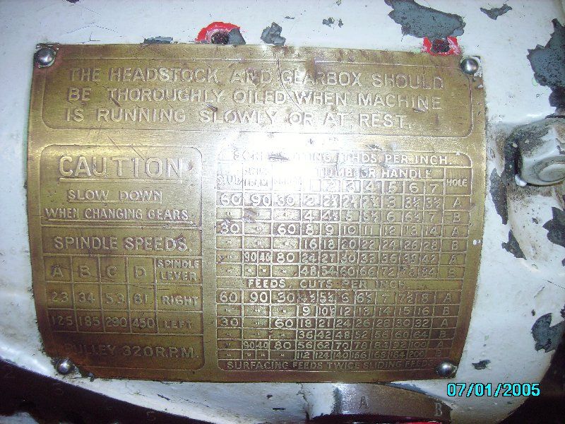
 1533 forum posts 147 photos | Here you go chaps! Sorry about the flash flare.
|
| Muzzer | 20/09/2014 20:29:43 |
 2904 forum posts 448 photos | In Chriss' last photo, the RH handle looks bent. In the first photo in the greenhouse it doesn't. It may just be the perspective of the wide angle camera but if not, could the handle have been damaged in transit? That would possibly explain why you can't pull the plunger and release the arm. Murray |
| CHRISTOPHER MILLS 1 | 20/09/2014 22:33:19 |
 152 forum posts 61 photos | Dear Murray, Many thanks, but the two photographs were taken same time, different angles - the lathe has not been moved yet. I feel the lever is rusted up. Phil supports the view. Many thanks for your interest - there is much to come yet off this CovMac. We are moving it in the next few weeks. I am a novice, and I am not quite sure exactly what this sticky lever does on this lathe. Clearly, it is part of the screw-cutting gearbox, but what it does, exactly, remains a little oblique. Best. Chris.
|
| CHRISTOPHER MILLS 1 | 21/09/2014 11:04:38 |
152 forum posts 61 photos | Planning the forthcoming CovMac lathe move: Tailstock, back gear guard and gap piece are removed and gone already. Bolts holding bed to tray and legs are all four removed. I do not think removing the headstock is going to be difficult, and I understand how to do it. All but one bolt is loose, and the other just needs a bit of dressing with a file, to get a socket onto it. To keep weight in the lift down, I want to remove the saddle carriage, too, but I do not yet fully understand the working of this. There is the lead screw and the power feed bar, which both run through the apron. The half nut onto the lead screw I understand, and with it disengaged the lead screw is no longer connected to anything in the apron? But what of the keyed power feed bar? This seems to have three positions governed by a lever on the apron, driving quadrant gears, for forward or backward feed, and these must be forward, reverse and disengaged? What I need to understand is connection between keyed power feed bar and the gearing mechanism in the apron - Will I be right in assuming that with the power bar selector in neutral positioning, that there is no longer anything in the apron touching the power feed bar? Tony's website shows the detailing of the apron. If so, then I should be able to disconnect the power bar and lead screw on the right hand end of the bed, under the tailstock, and, supporting both on the left hand side of the carriage, roll the carriage straight off the back of the bed, and then re-secure power bar and lead screw back into their bed fixings? Then I can lift and remove the bed and screw cutting gearbox, as one item. I do not want to remove the screw-cutting gearbox, as this looks beyond my limited experience. I am not now so much needing Brian to overheat my brain, I am beginning to do it myself!!
|
| CHRISTOPHER MILLS 1 | 21/09/2014 11:15:16 |
152 forum posts 61 photos | Phil, Many thanks for the close up of the Covmac's brass plate on the screw gearbox. I am beginning now to understand the controls. Oh, this lathe is going to be so much fun! I am seeking an old fashioned, brown engineer's apron to wear. Chris.
|
| Brian Wood | 21/09/2014 12:22:45 |
| 2742 forum posts 39 photos | Hello Chris, One thing I think might thwart your plans to roll the carriage off the bed might be the mounting lugs cast on the bed at the tailstock end that carries feedscrew and power shaft. You might have to remove the apron ]the bit with the controls etc] from the saddle to allow clearance and give yourself additional work. . My approach would be to leave it on the bed and if necessary roll it along the bed to help balance it when you are lifting it away from the legs. It is still a heavy lump of course but the bed is non symmetrical and thickest at the headstock end which will make it rather difficult to suspend well from a hook. I did notice in the pictures that there is a cross hole through the bed below the gap area; a possible slinging position perhaps? At least a rope or strop would not be able to move from that fixed point. With the other things removed I think the crane stands a chance of lifting bed/carriage combination I agree with you leaving the gearbox in place, it would not be difficult to refit as it is dowelled into position on the rear face, but it would all be added disturbance that you will need to restore later on. Phil Thank you for the gearbox plate picture. I have a special interest in lathe gearboxes and this one is rather unusual I am trying also to work out the ratios through the box, just for personal interest really, but could I ask you to measure the leadscrew pitch? I suspect it to be 4 per inch but I have no way of knowin for sure. And which way is the 7 step cone labelled, is it 1 to 7 reading left to right or the other way round? Again, I can't see that detail from the pictures. Chris again I can boil my own brain with these gearboxes quite easily, unlike you I am happy with maths! Your frozen gearbox handle will probably be of simple construction; an outer knurled thimble with a spring inside to keep it engaged in the chosen dimple. That will be fitted to a co-axial peg through a short bearing in the lever arm. The spring might have rusted to the inside of the thimble, rather unlikely I think, the peg which carries it all imay be rusted into the lever arm bearing, and least likely of all the shaft that links the arm into the gearbox has seized, that will have had oil splash from within the box to help it avoid that. I would get a grip on it with slip joint pliers and a thick rag to avoid bruising the knurling and try rotating it in either direction to free it off. It may simply be old paint holding it into the dimple. In use it is a speed change lever giving a 2:1 difference in ratio through the gearbox., Phil's plate shows it well. Enjoy some sunshine today, the first I've seen in 8 days Brian Edited By Brian Wood on 21/09/2014 12:25:14 |
| Ady1 | 21/09/2014 13:10:38 |
 6137 forum posts 893 photos | While I remember (cos I forget) once you finally get it home and set up you'll want to run it but it needs lubricated/cleaned. Most of the "grease nipples" on machines tend to actually be oil nipples A good pom-pom push-type grease gun can be used with oil to pump it in to the deeper recesses However, if you pump air alone into a nipple it can sometimes be useful for blowing a hole through old grease and oil passages which have gunked up over the last 50 years Then do it with clean oil (which now has a clearer route) gl |
| Ady1 | 21/09/2014 13:10:49 |
6137 forum posts 893 photos | dubble post Edited By Ady1 on 21/09/2014 13:11:29 |
| Phil Whitley | 21/09/2014 15:42:21 |
1533 forum posts 147 photos | Hi Brian, I am back at workshop tomorrow, I think you are right, I remember it as 4tpi, but will check tomorrow for you, anything else, just let me know. I was struck by the thought last week that I have finished the majority of the workshop rebuild, and soon I will be able to actually play with machines again, and build some heating "machines" for the workshop before the worst of winter sets in. Phil |
| CHRISTOPHER MILLS 1 | 21/09/2014 15:43:15 |
152 forum posts 61 photos |
Thanks Ady1 - this lathe is indeed very dirty, and you are right it needs a thorough clean. Some of the little oil filler caps need replacing, too. And it looks like it is missing two big oilers on the top headstock main bearings. Brian, I am glad you like gearboxes, as my acquiring this lathe has partly been prompted by deep curiosity about gears. I would really like to know how a gearbox works. I drive automatic cars, and once tried to imagine how an auto gearbox works - had to quickly stop thinking about that. Attached is a close up of the fixings for lead screw and power shaft on said CovMac. It looks to me like there will be nothing fixed on the bed, lug-wise, once that bracket holding the two rods is unbolted. The three drilled holes in that bracket, are they for oiling? The sleeving to the end of the lead screw might also need removing. You are probably right about leaving the carriage on the bed, but it will be the first time I have ever used an engine crane, and I am a bit nervous about it. I am going to have to remove it anyway, for the restoration, and if it just slides off, as I hope, I think I may do it. Using a steel rod through the eyehole, under the headstock, and one to the right, using the step to the bed, where it steps up towards the tailstock, I think we will balance it there, on twin chains. I will have to be careful the chain does not impinge on lead screw or power rod. Reading information on Phil's brass plaque, regarding spindle speeds, I just don't understand - it seems to suggest that any chosen set of positions, for the two spindle speed levers, gives two different speeds? How can that be? It clearly says (seems to me) that with both levers each set to position "D" it gives either 61 rpm, or 450 rpm. I am clearly missing some thing here - but I think I am personally still a few sandwiches short of an engineers' picnic What do you make of that? Chris.
|
| Brian Wood | 21/09/2014 15:57:19 |
| 2742 forum posts 39 photos | Hello Phil, Just when you have the time, there is no rush at all. While you are there don't forget to see which way round the gear selector slider is labelled, 1-7 reading out from left to right would seem right.. I take it the gearing down from the H'stock is conventional with two loose studs that are clamped to the banjo on which to mount gears. Regards Brian |
| Phil Whitley | 21/09/2014 16:21:21 |
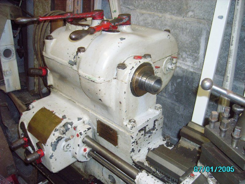
1533 forum posts 147 photos | Hi Chris, The main bearing oilers on mine are just two metal drop in plugs, which I thought a bit odd, but they are both painted red like all my oilers, so they date from at least the recon at IL Berridge (1954) I will take some pics of them, as they might be in the chip tray, or somewhere else in the shed where the lathe is. Phil. |
| CHRISTOPHER MILLS 1 | 21/09/2014 16:31:15 |
152 forum posts 61 photos | Phil, Yes, I would like to see "drop in" oiler plugs, as they are unknown to me. I quite fancied having a couple of glass jar type oilers, for ye olde worlde look to the CovMac. I will find it hard to resist impetus to take the lid off the headstock, to inspect the gearings, but did you say if I did this, the headstock bearings would need to be "re-set"? Which would be quite beyond me, of course. Is there a plug-hole at the bottom of the headstock, to drain the old oil out, like on a car's sump? How much oil do you think the headstock needs? The filler cap is simply enormous. Chris. |
| Phil Whitley | 21/09/2014 16:50:37 |
1533 forum posts 147 photos | You can see the main bearing oil cap in this pic, I will take one tomorrow of the cap itself, keep your eyes peeled for them when you are there next Phil |
| Phil Whitley | 21/09/2014 17:12:04 |
1533 forum posts 147 photos | Looking at the pics on lathes.co.uk, the oil caps look like they are original. Phil |
| CHRISTOPHER MILLS 1 | 21/09/2014 17:15:33 |
152 forum posts 61 photos | Phil, Looking at the headstock pics of mine, the right hand seems just a blank hole, definitely nothing there, but there is something in the left hand one - but it does not match yours. Chris.
|
| Brian Wood | 21/09/2014 17:29:33 |
| 2742 forum posts 39 photos | Hello Chris, Quite a lot to cover in reply so I will break it into sections 1 The leadscrew and power shaft bracket. It looks to have two small oiling holes, one to each shaft bearing. The larger diameter hole to the right of the hex head bolt is probably a dowel hole, with the dowel fitted to the bed. The whole will be mounted on a machined seating to keep things square. 2 You mention protecting the feedscrew and power shafts if you still have them in place when slinging the bed. The usual trick is to bridge over them with timber either side so that the sling is held away from contact and no side loading to them can occur. You DON'T want to bend those, the L'screw in particular. 3 Gearing I'll go over the headstock selectors as an example. My earlier thought some while ago was incorrect in thinking the RHS lever was for reversing the spindle drive. I've looked again at the open headstock picture on Tony Griffiths website and there are indeed 8 different spindle speeds possible. The left hand selector lever moves a spaced out cluster of 4 gears on a common carrier along the shaft furthest fro camera that brings power in via the input clutch. If you look at that picture you will see a long key runs the full length of that shaft to take the drive into the cluster. The selector arm allows one meshing at a time with the next shaft nearer the camera; you will see the different sized gears on that shaft to mesh individually. The gear spacings allow only one meshing for one position. This shaft is known as a layshaft [just a fancy name for a transfer shaft] and it is meshed selectively as described above. All 4 very visible gears are in fixed positions on the shaft and on the extreme right is a barely visible small 5th gear, also keyed to the layshaft, which meshes with the big gear nearest the chuck. It has a dog clutch formed on one side of it.. Two gears back on the laysheft, as shown in the picture, is a group of three gears,, all meshed together, across the full width of the gearbox.On the spindle shaft, the gear on the left also has a dog clutch on it's right hand end. It is free to rotate on the main spindle. The big gear on the right side of the dog clutch is also free to rotafe on the main spindle. Now this is the clever bit. The dog clutch is keyed on a slider to the main spindle and drive to the spindle is taken through that key, either from the gear on the left of it, or the big gear to the right. The dog clutch position is selected by the right hand lever on the top of the headstock and this gives the final 4 speeds to the spindle. Gears not coupled together are threfore free to rotate next to each other, and at different speeds. It takes a bit of thinking about, but if you make a sketch on paper and draw all 8 of the gear positions as a series, linked as they would be when engaged, I think you will see the logic of it 4 Your interpretation of Phil's plate Well yes, I agree with you, the gearbox would crash, so I'll look at that too and try to unravel it; it can't be as you are reading it I think today's work is quite enough for now Best wishes Brian
|
| Brian Wood | 21/09/2014 17:53:03 |
| 2742 forum posts 39 photos | Hello Chris, Last revelation for the day The Spindle speeds all make sense if you look at the setting for the lever called 'Spindle lever' This is the right hand lever that moves the dog clutch inside the headstock. You have 23, 34, 53 61 rpm with the lever to Right and 125, 185, 290, 450 with the lever to Left all respectively for the selector lever positions A, B, C and D Does that help? Brian
|
| CHRISTOPHER MILLS 1 | 21/09/2014 18:48:51 |
152 forum posts 61 photos | Brian, Many thanks, this is all fascinating stuff. I am going to beware saying anything makes sense, prematurely. My grandmother told me never to go off at half cock. Tomorrow, I am going to sit down with your words on one side, exploded view of the Covmac headstock, showing gears, on the other side. And I am going to study.... Your levers take makes sense if the right hand lever has only two positions, but I sort of think it has four, like the left hand one. (May be wrong, here, though, and I am nowhere near the lathe to check.) And on Phil's - both left and right levers are shown as possessing four positions A,B,C,D each, if you take each line as positions possessed by the lever. Each do seem to have four positions A,B,C,D. I think there is some key we are missing, so far, some occult device. We will get there in the end, I am sure. Now, had I paid more attention in my maths classes - oh, but my maths teacher was a harridan of a woman. And with the class mores of the time, because I went to Grammar School, I did not get to do any metalwork - now, you all have to suffer my ignorance on this forum!! Best. Chris.
|
| Phil Whitley | 21/09/2014 20:26:50 |
1533 forum posts 147 photos | I will sort all this out tomorrow chaps, but the right hand headstock lever on mine (spindle lever) has only two driving positions, and is in effect the high/low shift. It may have a centre neutral, can't remember at the moment. the left hand lever gives the four speeds ABCD,. So effectively, four in high ratio, and another four in low, making eight speeds in all. The banjo and the gears are off at the moment, but I have them all, but no 127 conversion gear, but if I need metric I use the Colchester. I haven't used the covmac yet, because it is in bits in the corner of what will be the "blacksmiths shop" although at the moment I call it the "machine shop", It actually looks more like a ragshop[! there is my Colchester student, a Harrison H mill, a Raglen V mill, and Alba No1 shaper,the Covmac and a Grafton drill press, Hidden away also in there is A startrite bandsaw, a floor standing Warco drill press, an Alfred Herbert precision drill press, and a brazing hearth. That's all the big stuff that I can think of at the moment anyway, all in a space a bit smaller than a single garage I can use the Colchester, the Grafton drill, and the Harrison provided I don't need too much table movement. The raglan is mid rebuild, as is a B&S dividing head, but I have forced myself to stop all non profit engineering until the building work is finished, So I have plenty of projects, and if you add to that the Fordson Major in the main workshop, the four2cv's inside, and another four outside, I am not going to be bored for the next couple of years at least! Phil |

Please login to post a reply.
Magazine Locator
Want the latest issue of Model Engineer or Model Engineers' Workshop? Use our magazine locator links to find your nearest stockist!
Sign up to our Newsletter
Sign up to our newsletter and get a free digital issue.
You can unsubscribe at anytime. View our privacy policy at www.mortons.co.uk/privacy
Latest Forum Posts
- hemingway ball turner
04/07/2025 14:40:26 - *Oct 2023: FORUM MIGRATION TIMELINE*
05/10/2023 07:57:11 - Making ER11 collet chuck
05/10/2023 07:56:24 - What did you do today? 2023
05/10/2023 07:25:01 - Orrery
05/10/2023 06:00:41 - Wera hand-tools
05/10/2023 05:47:07 - New member
05/10/2023 04:40:11 - Problems with external pot on at1 vfd
05/10/2023 00:06:32 - Drain plug
04/10/2023 23:36:17 - digi phase converter for 10 machines.....
04/10/2023 23:13:48 - More Latest Posts...
- View All Topics
Support Our Partners


Shopping Partners
Subscription Offer

Latest "For Sale" Ads
- Reeves** - Rebuilt Royal Scot by Martin Evans
by John Broughton
£300.00 - BRITANNIA 5" GAUGE James Perrier
by Jon Seabright 1
£2,500.00 - Drill Grinder - for restoration
by Nigel Graham 2
£0.00 - WARCO WM18 MILLING MACHINE
by Alex Chudley
£1,200.00 - MYFORD SUPER 7 LATHE
by Alex Chudley
£2,000.00 - More "For Sale" Ads...
Latest "Wanted" Ads
- D1-3 backplate
by Michael Horley
Price Not Specified - fixed steady for a Colchester bantam mark1 800
by George Jervis
Price Not Specified - lbsc pansy
by JACK SIDEBOTHAM
Price Not Specified - Pratt Burnerd multifit chuck key.
by Tim Riome
Price Not Specified - BANDSAW BLADE WELDER
by HUGH
Price Not Specified - More "Wanted" Ads...
Get In Touch!
Do you want to contact the Model Engineer and Model Engineers' Workshop team?
You can contact us by phone, mail or email about the magazines including becoming a contributor, submitting reader's letters or making queries about articles. You can also get in touch about this website, advertising or other general issues.
Click THIS LINK for full contact details.
For subscription issues please see THIS LINK.
Digital Back Issues


Donate

 Register
 Log-in
Model Engineer Magazine
- Percival Marshall
- M.E. History
- LittleLEC
- M.E. Clock

ME Workshop
- An Adcock
- & Shipley
- Horizontal
- Mill

Subscribe Now
- Great savings
- Delivered to your door

Pre-order your copy!
- Delivered to your doorstep!
- Free UK delivery!
All Forum Topics > Beginners questions > CovMac Lathes