Forum sponsored by:

Stuart 10V Build Log - Complete Beginner...
| Dr_GMJN | 28/05/2020 15:36:36 |
 1602 forum posts | Posted by Martin Connelly on 28/05/2020 15:25:44:
Have you seen this thread? I had to go back a few pages to find it. Martin C No - But I like it. Cheers! |
| JasonB | 28/05/2020 16:49:29 |
 25215 forum posts 3105 photos 1 articles | I usually do the same as you did and slip a couple of parallels between chuck face and back of work |
| Dr_GMJN | 28/05/2020 16:51:56 |
1602 forum posts | Posted by JasonB on 28/05/2020 16:49:29:
I usually do the same as you did and slip a couple of parallels between chuck face and back of work And remove them before machining, rather than securing them somehow? Thanks. |
| JasonB | 28/05/2020 17:33:47 |
25215 forum posts 3105 photos 1 articles | Yes, 99% of the time I would remove them, on the odd occasion where there may not be much metal to grip and therefore a risk of the cut pushing the work back I will either wire or zip tie them in place
Edited By JasonB on 28/05/2020 17:36:43 |
| Dr_GMJN | 28/05/2020 23:14:42 |
1602 forum posts | Posted by JasonB on 28/05/2020 17:33:47:
Yes, 99% of the time I would remove them, on the odd occasion where there may not be much metal to grip and therefore a risk of the cut pushing the work back I will either wire or zip tie them in place
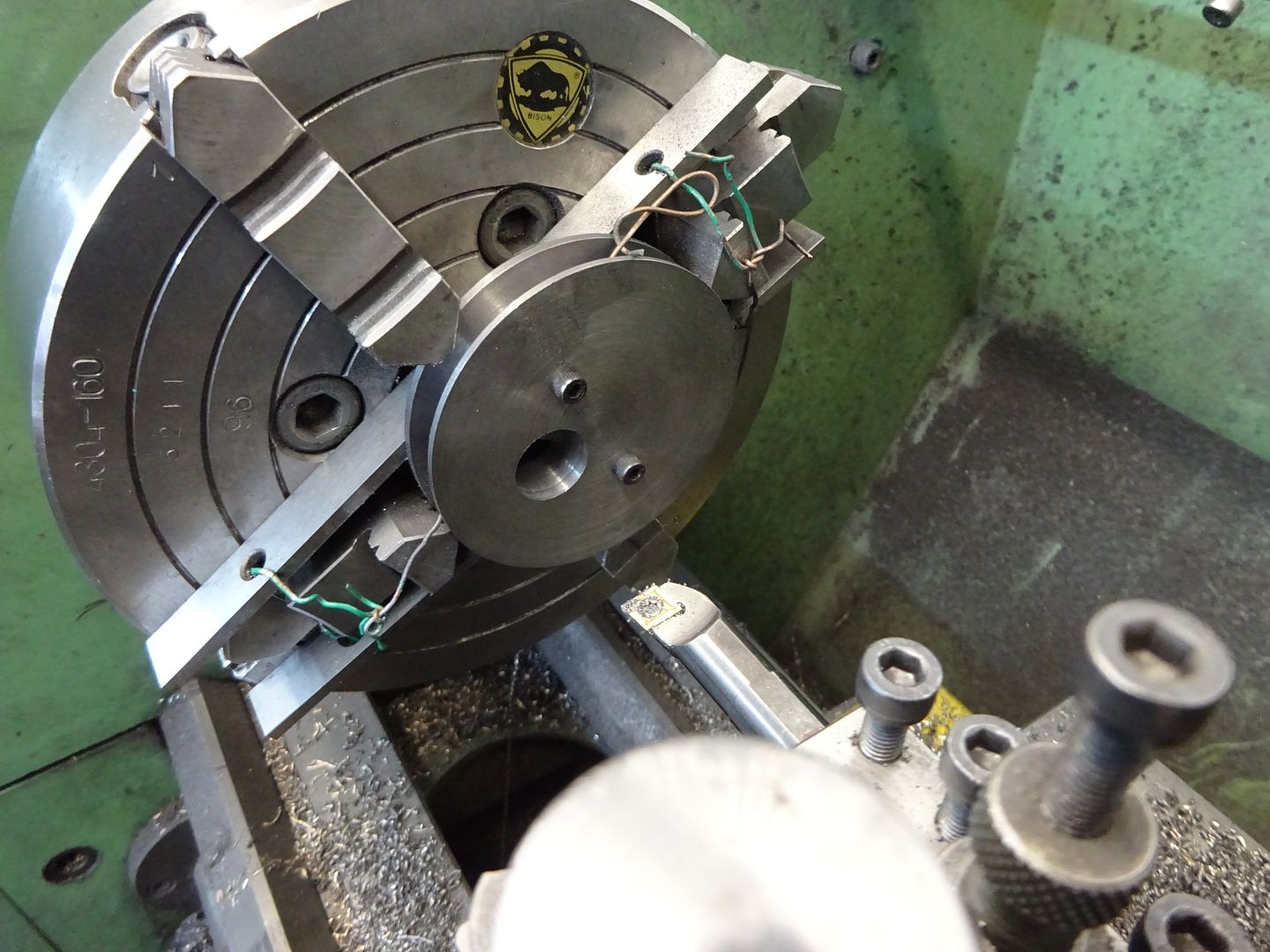
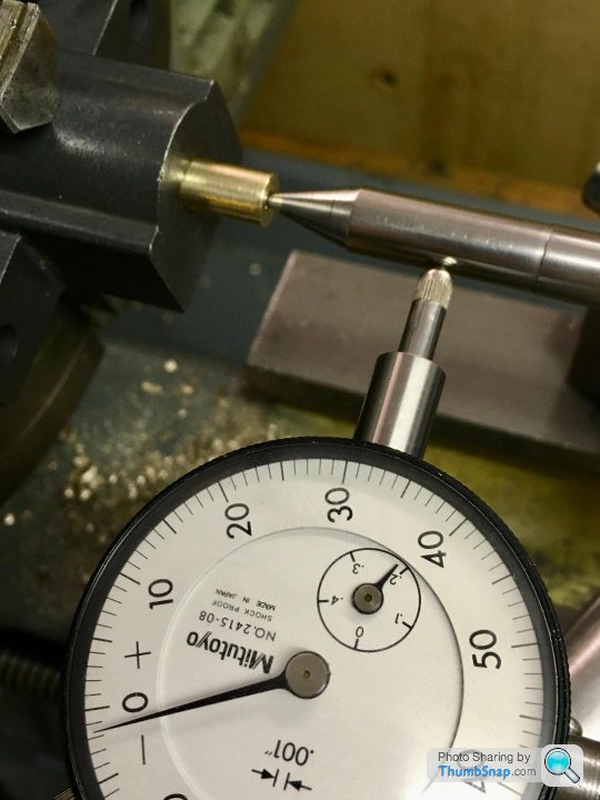
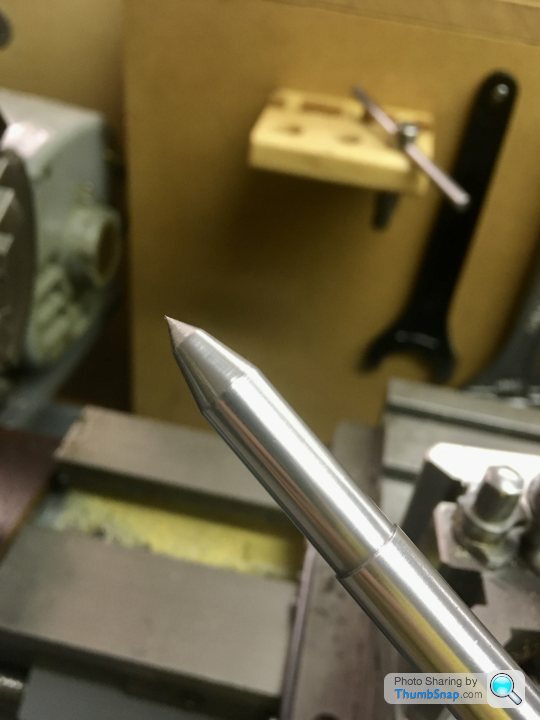
Edited By JasonB on 28/05/2020 17:36:43 OK great, so I used the same method as that tonight for the other handwheel block. One change I made was to turn a brass spigot to knock into the existing bush in the block. The spigot had no measurable runout. I was able to easily center the block in the 4 jaw chuck using a DTI on the spigot so there was no measurable runout. I'd centre drilled the spigot, so as an experiment, I used my centering rod again: Any thoughts on what I'm doing wrong here? Anyhow, the block got machined - I calibrated the depth stop as suggested (but used calipers rather than slip gauges) - and the bearings were fitted. Both X & Y axes on the mill are now really smooth with minimal backlash. Thanks! |
| Ron Laden | 29/05/2020 04:33:35 |
 2320 forum posts 452 photos | If the spigot has zero runout then I would suspect the centering bar and where you are measuring on the bar, have you tried measuring close up against the spigot? I measure close up against where the bar contacts the part.
Edited By Ron Laden on 29/05/2020 04:43:18 |
| Dr_GMJN | 29/05/2020 06:09:03 |
1602 forum posts | Ron - I’m measuring about 1” back along the bar from the part. Since I’m measuring wobble rather that runout of the bar itself (assuming I stop it rotating) I don’t get why I can’t zero it - presumably in theory it doesn’t matter where along the bar I measure, but the biggest reading will be nearest the workpiece? |
| JasonB | 29/05/2020 07:09:01 |
25215 forum posts 3105 photos 1 articles | I think your angle on the end of the rod may be the problem. A ctr drilled and even a spot drilled hole will have a very slight flat on the bottom, your ctr punch mark from the other day will leave a wide 90deg cone and again may not have a perfectly flat bottom. Now your very sharp pointed low angled indicator rod will touch the bottom of your mark not and not sit taper to taper. So I would suggest you recut the end taper to 60deg inclusive angle, use a dot (prick) punch which are also ground to 60deg and if drilling to mark the position then use a small BS0 ctr drill and go in all the way with the pilot plus a small amount of the part that cuts the 60deg seat. One other thing to bear in mind when making something like that plug, if your 3 jaw is a bit out it is unlikely the hole is concentric to the OD of the plug. For a job like this where there is an existing hole you would be better off just setting the lever of the dti to run against the inside of the hole, save the rod for when there is no suitable hole. |
| Dr_GMJN | 29/05/2020 09:18:01 |
1602 forum posts | Thanks Jason, OK I'll re-cut the point again to 60 degrees inclusive. And I'll re-turn a portion of the adjacent shaft too. Is there a good way of re-profiling one of my centre punches to 60 degrees too? BTW the punch holes so far are only in the bras bearings - for the spigot yesterday I did centre drill it to make sure the point didn't bottom out. The spigot was turned in a collet, but of course if the center drill wandered it wouldn't be central. Also, I tried the bar in the existing through hole in the handwheel block, so it was in there to about half the taper depth (and obviously there was no bottom to it). Same story with runout. Anyway, I'll re-cut it and try again.
|
| Dr_GMJN | 31/05/2020 16:41:55 |
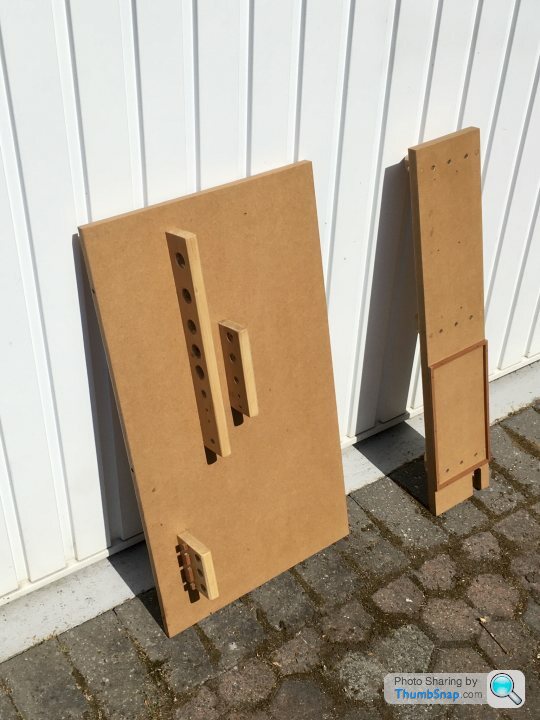
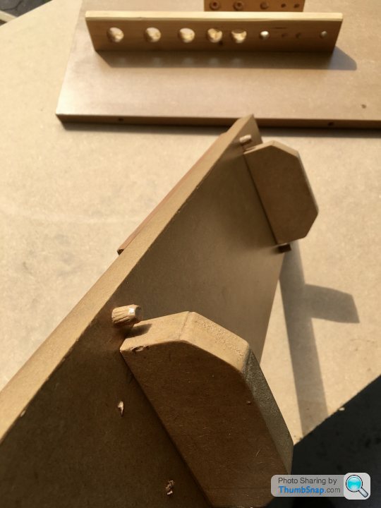
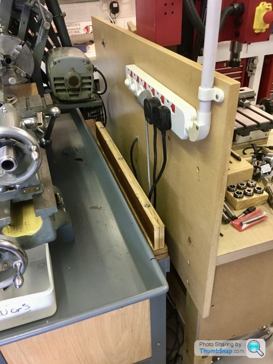
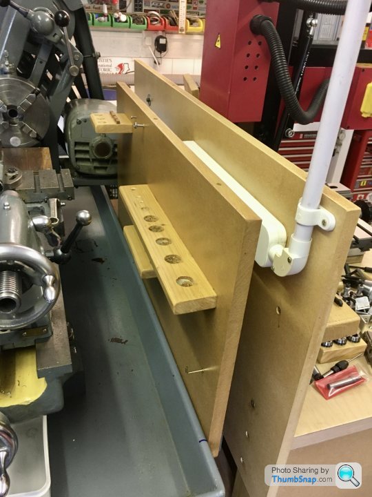
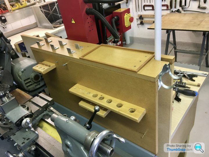
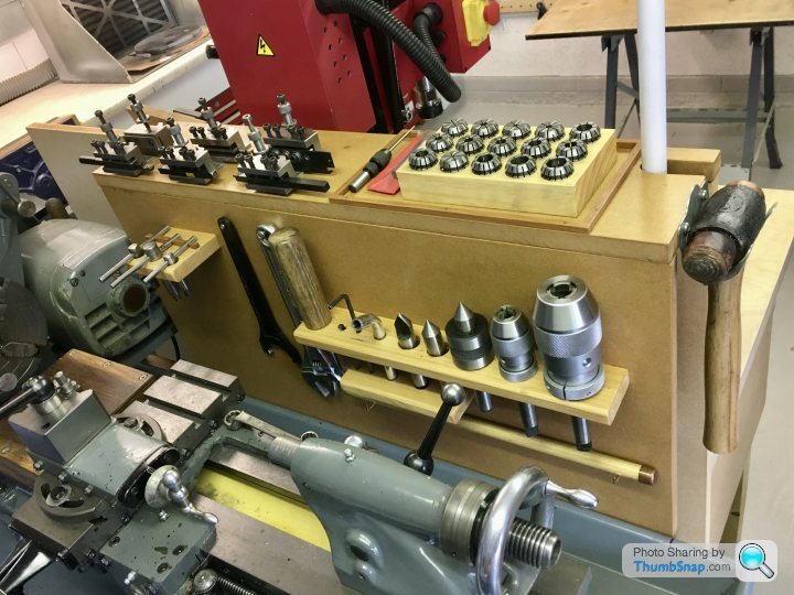
1602 forum posts | I sacrificed a day on the 10V to make a tool board/shelf for the lathe and milling machines. I was wasting loads of time looking in my tool chest drawers for things. I’ve made it all slot together so I can quickly separate the two benches if I need to move them. Common tools like the collets and soft hammer are in the middle. I cut some aluminium angle up to put the lathe tool holders on. |
| Dr_GMJN | 01/06/2020 23:06:55 |
1602 forum posts | I've sidetracked this thread a bit, but now back to the 10V - the main bearings. |
| Dr_GMJN | 02/06/2020 09:08:26 |
1602 forum posts |
|
| Martin Connelly | 02/06/2020 09:27:19 |
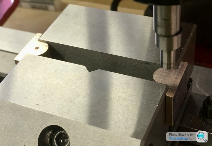
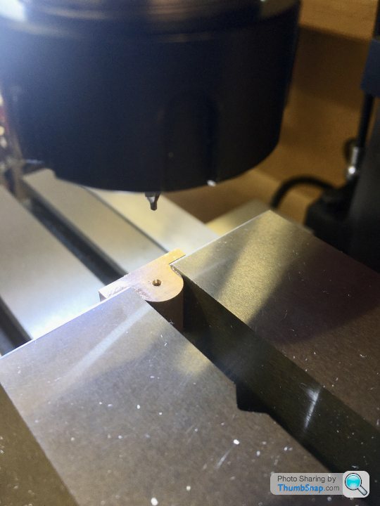
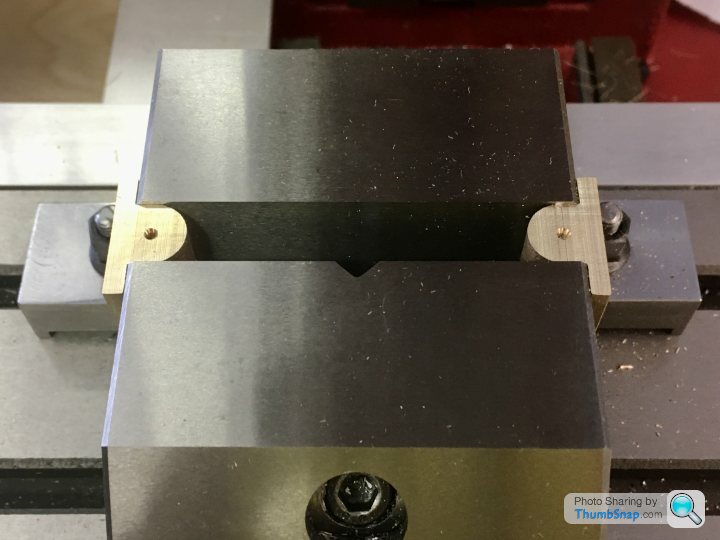
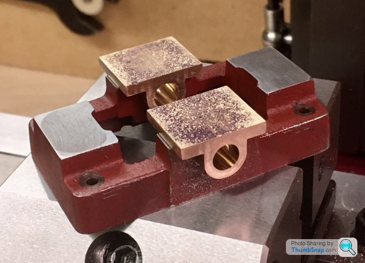
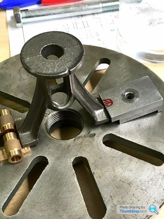
 2549 forum posts 235 photos | I would not get in the habit of holding two parts at once in the vice like that. There is always the chance that one is not held as tightly as you think and will come loose when it is being machined. It is relying on the two parts being nearly/exactly the same width where they are gripped and the vice being sloppy enough to twist the moving jaw to even out the grip on the two parts. Copper and its alloys are grabby, the bearings could easily have been twisted out of the ends of the vice if a drill had been grabbed by the alloy. One at a time in the centre of the vice may seem a bit slower but it is going to give a better grip and twisting of the workpiece would be next to impossible. I would suggest a vice stop and parallels would help when you have more than one item to machine the same way. Parallels support the part solidly. Your method of holding them could cause them to be pushed downwards. If you had asked if it was a good setup to drill them I would have emphatically said no. Just for marking out is not a problem but it is something to think about for the future. Martin C Edited By Martin Connelly on 02/06/2020 09:30:10 |
| Dr_GMJN | 02/06/2020 11:04:02 |
1602 forum posts | Posted by Martin Connelly on 02/06/2020 09:27:19:
I would not get in the habit of holding two parts at once in the vice like that. There is always the chance that one is not held as tightly as you think and will come loose when it is being machined. It is relying on the two parts being nearly/exactly the same width where they are gripped and the vice being sloppy enough to twist the moving jaw to even out the grip on the two parts. Copper and its alloys are grabby, the bearings could easily have been twisted out of the ends of the vice if a drill had been grabbed by the alloy. One at a time in the centre of the vice may seem a bit slower but it is going to give a better grip and twisting of the workpiece would be next to impossible. I would suggest a vice stop and parallels would help when you have more than one item to machine the same way. Parallels support the part solidly. Your method of holding them could cause them to be pushed downwards. If you had asked if it was a good setup to drill them I would have emphatically said no. Just for marking out is not a problem but it is something to think about for the future. Martin C Edited By Martin Connelly on 02/06/2020 09:30:10 Thanks Martin - understood; I wouldn't consider any significant machining operation while holding parts like that. My thoughts were: 1) The casting has been cut in half, and so the width is essentially the same for both parts - they measured exactly the same with my calipers. If they'd have measured differently I wouldn't have tried it, not least becasue as you say the jaws wouldn't have been parallel, which would have affected the reading, and not done the vice any good. 2) I was only centre drilling to a couple of mm, so very low forces involved. On the face of it, it seemed like a good way of getting around the issue of not having enough room to find an edge. |
| Dr_GMJN | 02/06/2020 23:34:26 |
1602 forum posts | Turned a bearing mandrel from some scrap brass rod, and threaded the end M5: |
| Dr_GMJN | 03/06/2020 09:33:55 |
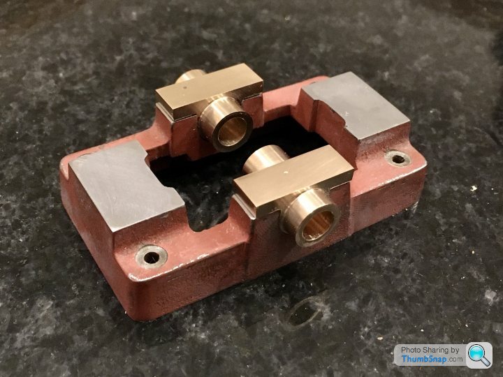
1602 forum posts | All, I'd like to put a very small chamfer around the top edge of the rectangular bearing plates. It looks like I've got about 1mm clearance between the top of the boss and the top surface, so a 0.5mm x 45 degree chamfer all around should be OK. I have a 45 degree chamfering tool. I tried chamfering around my travel stop and it worked OK for what it was, but for this, I need to be very precise. What I found with aluminium was it was difficult to determine when the tool had touched the edge of the work, becasue it was soft. I think it'll be similar with brass. If the chamfer is only 0.5mm, then any excess cut depth would give an inconsistent chamfer width. Any tips for setting up this job for chamfering? I suppose everything has to be absolutely square and level before cutting, but these parts are quite small. Thanks! |
| JasonB | 03/06/2020 10:04:15 |
25215 forum posts 3105 photos 1 articles | Probably quicker to file than set up and mill. If you really want to machine it then a but of simple maths once you have located the edge, and end of tool should get a consistent result |
| Dr_GMJN | 03/06/2020 10:16:02 |
1602 forum posts | Posted by JasonB on 03/06/2020 10:04:15:
Probably quicker to file than set up and mill. If you really want to machine it then a but of simple maths once you have located the edge, and end of tool should get a consistent result Thanks Jason, so if machining, you'd calculate the offset to put into the machine, or would you mark out and cut up to the line? I was thinking that cutting to a line once the tool depth is set to give a small excess, it would eliminate any errors in initial setting when using the DROs. I was going to mark out and file (might still do that), but the area around the top of the boss is difficult to access. |
| JasonB | 03/06/2020 10:21:08 |
25215 forum posts 3105 photos 1 articles | I would not mark it out. Though you could blue the whole thing to make it easier to see what you have cut as a double check. |
| Dr_GMJN | 03/06/2020 23:01:14 |
1602 forum posts | OK, I'll ponder the chamfers a bit more while I get the holes drilled and the the bores reamed. |

 |https://thumbsnap.com/oNw6VGNc[/url]
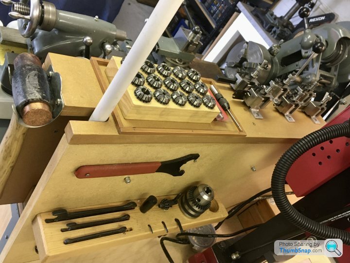


Please login to post a reply.
Magazine Locator
Want the latest issue of Model Engineer or Model Engineers' Workshop? Use our magazine locator links to find your nearest stockist!
Sign up to our Newsletter
Sign up to our newsletter and get a free digital issue.
You can unsubscribe at anytime. View our privacy policy at www.mortons.co.uk/privacy
Latest Forum Posts
- *Oct 2023: FORUM MIGRATION TIMELINE*
05/10/2023 07:57:11 - Making ER11 collet chuck
05/10/2023 07:56:24 - What did you do today? 2023
05/10/2023 07:25:01 - Orrery
05/10/2023 06:00:41 - Wera hand-tools
05/10/2023 05:47:07 - New member
05/10/2023 04:40:11 - Problems with external pot on at1 vfd
05/10/2023 00:06:32 - Drain plug
04/10/2023 23:36:17 - digi phase converter for 10 machines.....
04/10/2023 23:13:48 - Winter Storage Of Locomotives
04/10/2023 21:02:11 - More Latest Posts...
- View All Topics
Support Our Partners


Shopping Partners
Subscription Offer

Latest "For Sale" Ads
- Reeves** - Rebuilt Royal Scot by Martin Evans
by John Broughton
£300.00 - BRITANNIA 5" GAUGE James Perrier
by Jon Seabright 1
£2,500.00 - Drill Grinder - for restoration
by Nigel Graham 2
£0.00 - WARCO WM18 MILLING MACHINE
by Alex Chudley
£1,200.00 - MYFORD SUPER 7 LATHE
by Alex Chudley
£2,000.00 - More "For Sale" Ads...
Latest "Wanted" Ads
- D1-3 backplate
by Michael Horley
Price Not Specified - fixed steady for a Colchester bantam mark1 800
by George Jervis
Price Not Specified - lbsc pansy
by JACK SIDEBOTHAM
Price Not Specified - Pratt Burnerd multifit chuck key.
by Tim Riome
Price Not Specified - BANDSAW BLADE WELDER
by HUGH
Price Not Specified - More "Wanted" Ads...
Get In Touch!
Do you want to contact the Model Engineer and Model Engineers' Workshop team?
You can contact us by phone, mail or email about the magazines including becoming a contributor, submitting reader's letters or making queries about articles. You can also get in touch about this website, advertising or other general issues.
Click THIS LINK for full contact details.
For subscription issues please see THIS LINK.
Digital Back Issues


Donate

 Register
 Log-in
Model Engineer Magazine
- Percival Marshall
- M.E. History
- LittleLEC
- M.E. Clock

ME Workshop
- An Adcock
- & Shipley
- Horizontal
- Mill

Subscribe Now
- Great savings
- Delivered to your door

Pre-order your copy!
- Delivered to your doorstep!
- Free UK delivery!
All Forum Topics > Work In Progress and completed items > Stuart 10V Build Log - Complete Beginner...