Forum sponsored by:

Myford ML4 Restoration: Headstock bearings and spindle removal
| Jon Cameron | 07/05/2020 08:57:40 |
| 368 forum posts 122 photos | Posted by Luke Mitchell on 06/05/2020 21:57:17:
The gap that I measured was between the ways themselves but it did occur to me, as I took this photograph, that the space below the ways could be used as a clamping surface. I'm not sure what this distance is as I don't have any telescoping gauges with which to measure it. Perhaps I was mistaken in my understanding and this is the clamping surface always used?
Hi Luke, Above photo, the lower surface on the underneath of the beds ways, is the clamping surface the fixed steady uses on my lathe. mine measures 1/4" but is tight on two ribs so 3/16" may be a better thickness for the clamp. As with my reply above buy two feeler gauge sets from toolstation or similar, mine cost around £5 each. you can then measure the gap on the underside of the ways for reference, and use both to check the gap when reinstalling the spindle. been able to clamp the bolts tight down onto the gauges while checking the spindle still turns freely.
Jon |
| Brian Wood | 07/05/2020 09:47:33 |
| 2742 forum posts 39 photos | Hello Luke, This gets ever more interesting. You and Jon have far more experience with these bearing bushes than I had. Dad never touched them other than to adjust for correct running. Neither he nor I fiddled with the grub screws and as Robert Atkinson has observed, maybe they need replacing. Certainly the slits should align with the split in the bearing housings, the shells will be unable to close otherwise. I would be guided by the position of the oil holes as to whether they have been transposed at some time, but from the condition they seemed to be in as shown in your earlier pictures, they don't need replacing in my view, nor that of Howard Lewis; it is more a case of deciding if they have been mixed up and getting them back where they belong. The cracked gear. Well now, it is so obvious once the dog can see the rabbit. When you come to repair it you do need to ensure the tooth gap across crack [which you will have sawn out by now] is the same as that for the other teeth. Measure adjacent tooth gaps with your calipers over the outside of the teeth and note the values. Then do the same measurement over the one to repair and adjust the value by squeezing it up carefully in your vice before you apply the heat and braze metal. Do make sure you have a support below it to stop it dropping within the vice jaws when it gets hot. Measured that way it is so much easier than trying to get consistency in the narrow gap right above the root of a tooth. I think you will find the gear has opened up slightly, the crack has width and will have eased some local stress. It is still a curiosity to me though !! Kind regards Brian Edited By Brian Wood on 07/05/2020 09:49:15 |
| Luke Mitchell | 07/05/2020 09:54:47 |
 39 forum posts 21 photos | Hi again all, Posted by Brian Wood on 07/05/2020 09:47:33:
This gets ever more interesting. You and Jon have far more experience with these bearing bushes than I had. Dad never touched them other than to adjust for correct running. Neither he nor I fiddled with the grub screws and as Robert Atkinson has observed, maybe they need replacing. Certainly the slits should align with the split in the bearing housings, the shells will be unable to close otherwise. I would be guided by the position of the oil holes as to whether they have been transposed at some time, but from the condition they seemed to be in as shown in your earlier pictures, they don't need replacing in my view, nor that of Howard Lewis; it is more a case of deciding if they have been mixed up and getting them back where they belong. Brian, I've already repositioned the bearings so that the splits line up with those in the housings. Next time I work on the lathe I'll take some more photographs - I may extract the bearings again to double-check that they are positioned in the correct location but I am almost certain that they are. Once the new thrust bearing arrives I'll reassemble and take some measurements to see if I've managed to improve things. I am quietly confident. Kind regards |
| Robert Atkinson 2 | 07/05/2020 15:56:53 |
 1891 forum posts 37 photos | Jon, Robert G8RPI. |
| Luke Mitchell | 07/05/2020 16:06:55 |
39 forum posts 21 photos | Posted by Robert Atkinson 2 on 07/05/2020 15:56:53:
Jon, Robert G8RPI. Hi Robert, I've seen and read mention of these grub screws in many places - so many that I had assumed the machines were like that from the factory. My understanding is that the grub screws were used to prevent the bearing from rotating in the casting (which they seem to have failed to do on my machine). Interestingly, during my searches, I've come up with lots of photographs of machines with these grub screws but lots of them do seem to be in different locations. Perhaps these are all after-market modifications! See this photo (linking as it's not mine to post) in which the grub screw is just visible on the left-hand headstock bearing casting. See also this thread (on this forum) and this photo (also linking as it's not mine). |
| Jon Cameron | 07/05/2020 16:12:35 |
| 368 forum posts 122 photos | Is one of the headstocks cast as one with the bed? if so it wouldn't need the grub screws, as the spindle runs against the cast iron headstock. There is numerous examples that show the grub screws to retain the bearings from spinning. You only have to do a google image search to see them. There is also a lot spoken across forums about the inherent weakness across the oiling point and bearing retaining screw holes if you over tighten them. I cant see that many examples of owners deciding off their own back to drill their headstock out and tap them for the BSF retaining screw. So although its not mentioned it is not to say that its not standard fit for the production. of myfords. Much as the adjusting screws for the half nuts are not mentioned but there still there. |
| Jon Cameron | 07/05/2020 16:23:29 |
| 368 forum posts 122 photos | Hi Luke thanks for the links, What's interesting to note is that the last lathe is an A1 which was built by Drummond allowing myford to concentrate on other manufacture. A1 and A2 denotes the ML4 and ML2 respectively. The position of the screws could be an indication of who built the lathe. Considering the second one, is another example of lathe that is missing the myford cast onto the side. and the offset position yet again of the grub screws in the same position as the last, could indicate these were both build by Drummond. Or at least in the later years of production. |
| Jon Cameron | 07/05/2020 16:52:21 |
| 368 forum posts 122 photos | Hi Robert, just had a look at your photos of the ML2 in your photos, It appears that it doesn't have the grub screws, but yours is an early version of the ML2, note the difference in the bolt arrangement for the headstock at the chuck end. yours isn't rounded off to meet the bed, but instead has two flats. earlier ones were bolted from above, yours seems to be bolted from underneath but still retains the older casting. If you wouldn't mind i'm compiling a list of myford serial numbers and differences between them all throu 1-4 types. Would you be able to tell me what the serial number of yourML2 is please? |
| Robert Atkinson 2 | 07/05/2020 16:59:18 |
1891 forum posts 37 photos | Hi, I didn't post any photos...... Robert G8RPI Edited By Robert Atkinson 2 on 07/05/2020 17:04:23 |
| Brian Wood | 07/05/2020 18:27:29 |
| 2742 forum posts 39 photos | Jon, If it helps you in compiling your machine record, my Dad'd ML4 was purchased new in 1945 and sported the serial number D 2382. That was stamped onto pretty much everything, even including the spindle around the hole at the gear end. It also included that 25 tooth gear. Regards Brian |
| Jon Cameron | 07/05/2020 22:31:56 |
| 368 forum posts 122 photos | Robert yes sorry I wasn't clear, the ML2 in your album photos. If you don't mind as I said I'm compiling a list with a view to show differences and try and date the lathes, unfortunately Myford destroyed all the papers and records, including customer details and addresses, for the older lathes. Probably a wise move in this day and age of data protection but sadly does nothing to date the old myfords. Brian, that's very helpful, if you happen to have a picture or can show some differences, your dad's lathe with that info dates two others from the myford Facebook group. I now have two dates one for lathes starting LH, of which mine is, and yours which means I can date five of the lathes I have serial numbers for with a fair degree of accuracy. It's all jotted down at the moment and I need to get it digitised along with photos to show the various differences such as the headstock changes from bolting from the top into the bed, then later bolting into the headstock through the bed. A long mission an I did post on the forum but haven't recieved much response in regards to serial numbers or photos of lathes. So far with regards to serial number stamping, I have seen it on the leadscrew end, base of the headstock, saddle, cross slide, tailstock, and obviously bed too. I suppose it made sense with the volume produced that everything had a serial number so headstock and tailstock didn't get mixed up ect. Edited By Jon Cameron on 07/05/2020 22:35:08 |
| Brian Wood | 09/05/2020 10:17:06 |
| 2742 forum posts 39 photos | Hello Jon, In your last post on 7th May you asked if I might have a picture of two of Dad's old ML4 lathe. Alas no. Photos of machinery were less common in those days, film cameras and expensive processing were the order of the day and sadly it simply didn't occur to me to record things in that way. Sorry I can't help any further with compiling your record of these earlier lathes. Kind regards Brian Edited By Brian Wood on 09/05/2020 10:17:39 |
| Brian Wood | 11/05/2020 14:49:01 |
| 2742 forum posts 39 photos | For those who were following this thread closely. This is really to record my changed attitude to the question of nose registers about which David Bennett made a bold and somewhat controversial statement, in this thread, that the horizontal register was in fact not necessary. Being traditional in my view of these features I challenged him but he has produced some convincing evidence to support that what he stated holds water. In particular I suggested he turned a faceplate round and mounted it in reverse on the nose. This he has done, butting up to a machined collar behind it that abuts only the vertical register . Lo and behold , it runs perfectly true mounted in this way, despite the lack of any horizontal register. This also was the case found by Tony Griffiths of lathes.co.uk fame with at least two chucks and by David with two chucks of ML7 nose location screwed directly onto his ML4 nose. All these ran true even under heavy working and supported with his knowledge of a Wolf-Kahn lathe that uses only the vertical register for chuck location. So, it would seem that a holy grail has been punctured. The truly critical location is the vertical register, the horizontal register that we have all striven to get exactly sized over the years is acting as little more than a guide. Of course, with the increasing use of camlock location on hobby sized equipment, it has been used industrially for many years, the whole discussion might be regarded as academic. I apologise to Luke Mitchell for hijacking what was his thread, but it might be interesting to see what others make of this interesting new evidence Regards Brian Edited By Brian Wood on 11/05/2020 14:51:42 |
| Jon Cameron | 11/05/2020 15:09:36 |
| 368 forum posts 122 photos | Hi Brian, That's how my lathe has "registered" its chuck on a vertical face behind the thread, the thread been a guide and then the vertical face holding the backplate true to the front faced surface for the chuck. Although ive not turned any large diameter, it seems that ive been able to machine quite happily the smaller items I have done. I believe my spindle has been modified at some point in its life from 1.1/8" to 7/8" 9TPI, perhaps to use existing tooling, the register has nearly all been turned down, sadly. There was an article from Martin Cleave in ME about the large bore conversion he did for his ML4, which would show the dimensions of the nose thread and any register, either vertical or horizontal. Wish we knew where his lovely lathe was today. Regards Jon |
| Brian Wood | 11/05/2020 17:35:32 |
| 2742 forum posts 39 photos | Hello Jon, I don't like to correct you but, Martin Cleeve's lathe was I think an ML7, not ML4. Like you it would be interesting to know where his lathe fetched up; hopefully with someone who would have appreciated it in it's modified form And yes, David's work has shown that a reasonable fit on the thread, to stop the chuck actually flopping about, backed up by solid contact with the vertical register does the business. So press on as you are doing! Kind regards Brian |
| Jon Cameron | 11/05/2020 18:48:11 |
| 368 forum posts 122 photos | You have me wondering now, I'm sure the article was written to convert the 3/8" bore upto a 5/8" bore, so that 1/2" stock could be passed through the bore. I'll have to hunt out the article |
| Brian Wood | 12/05/2020 09:48:58 |
| 2742 forum posts 39 photos | Hello Jon, It would be useful if you can find the article. If your memory of such material is anything like mine has become, you may find it is nothing like what you think it was ! By the way, the spindle bore on my ML7R is a nominal 5/8", in common with the standard ML7. Even the ML4 had a bore greater than 3/8" surely? With a spindle diameter of 1 inch, that leaves plenty of wall thickness and enough to contain the 2MT socket that the later version such as my Dad bought were equipped with. Kind regards Brian
|
| Luke Mitchell | 12/05/2020 09:56:12 |
39 forum posts 21 photos | Just to chip in, I have measured my spindle bore as being slightly greater than 15mm. A piece of 15mm diameter stock will pass through easily. I suspect the bore of my ML4 is also 5/8" (15.88mm) although I've not measured it so accurately. |
| Jon Cameron | 12/05/2020 10:33:15 |
| 368 forum posts 122 photos |
Hi Brian, Luke Ive found the article by Martin Cleeves. It is indeed for an ML4, my spindle has the earlier spindle and nose thread of 7/8" 9TPI, therefore it only accommodates an MT1 taper and passes 3/8" stock. Below youll see a scan of the article, which also shows a grinder attachment for the rear of the lathe spindle. Something handy if you only have the one motor, though not recommended as the dust and grit would not do your precious lathe much good. Though the rest would be handy for setting up in front of a bench grinder, to assist with grinding HSS, or Carbide tooling. Something that Luke might like to look into for his tool grinding, it is certainly something ill be doing.
|
| Luke Mitchell | 15/05/2020 13:27:02 |
39 forum posts 21 photos | Hi again all, Last night I reassembled my headstock, complete with new thrust bearing (sadly of much worse quality than the SKF one which did not fit - but it was the best I could find) and some new power-twist belts for ease of adjustment. When I first turned on the lathe there was a bit of a knocking sound coming from the headstock, once per revolution. I double-checked the bearing tightness, which was snug but not over-tight, and decided to run the motor for a little bit to see if it resulted in any heat. After 20 minutes the sound lessened a bit and the bearings were only very slightly warm to the touch. I then took some light cuts on aluminium, brass and then steel. Trying to part the aluminium/steel was unpleasant, although less chattery than previously. I was able to part the brass very cleanly. There is a bit of slop in the handwheels and the backgear assembly that I am going to take out using fiber washers. I think this will help dampen the vibrations and make using the lathe a little more pleasant. I also need to thoroughly examine the headstock to determine where the noise is coming from - it seems as though it's coming from the chuck-side bearing but there is a chance it's the new belt. I've attached a video and I wonder if someone is able to give their opinion on the noise? Kind regards |


Please login to post a reply.
Magazine Locator
Want the latest issue of Model Engineer or Model Engineers' Workshop? Use our magazine locator links to find your nearest stockist!
Sign up to our Newsletter
Sign up to our newsletter and get a free digital issue.
You can unsubscribe at anytime. View our privacy policy at www.mortons.co.uk/privacy
Latest Forum Posts
- hemingway ball turner
04/07/2025 14:40:26 - *Oct 2023: FORUM MIGRATION TIMELINE*
05/10/2023 07:57:11 - Making ER11 collet chuck
05/10/2023 07:56:24 - What did you do today? 2023
05/10/2023 07:25:01 - Orrery
05/10/2023 06:00:41 - Wera hand-tools
05/10/2023 05:47:07 - New member
05/10/2023 04:40:11 - Problems with external pot on at1 vfd
05/10/2023 00:06:32 - Drain plug
04/10/2023 23:36:17 - digi phase converter for 10 machines.....
04/10/2023 23:13:48 - More Latest Posts...
- View All Topics
Support Our Partners


Shopping Partners
Subscription Offer

Latest "For Sale" Ads
- Reeves** - Rebuilt Royal Scot by Martin Evans
by John Broughton
£300.00 - BRITANNIA 5" GAUGE James Perrier
by Jon Seabright 1
£2,500.00 - Drill Grinder - for restoration
by Nigel Graham 2
£0.00 - WARCO WM18 MILLING MACHINE
by Alex Chudley
£1,200.00 - MYFORD SUPER 7 LATHE
by Alex Chudley
£2,000.00 - More "For Sale" Ads...
Latest "Wanted" Ads
- D1-3 backplate
by Michael Horley
Price Not Specified - fixed steady for a Colchester bantam mark1 800
by George Jervis
Price Not Specified - lbsc pansy
by JACK SIDEBOTHAM
Price Not Specified - Pratt Burnerd multifit chuck key.
by Tim Riome
Price Not Specified - BANDSAW BLADE WELDER
by HUGH
Price Not Specified - More "Wanted" Ads...
Get In Touch!
Do you want to contact the Model Engineer and Model Engineers' Workshop team?
You can contact us by phone, mail or email about the magazines including becoming a contributor, submitting reader's letters or making queries about articles. You can also get in touch about this website, advertising or other general issues.
Click THIS LINK for full contact details.
For subscription issues please see THIS LINK.
Digital Back Issues


Donate

 Register
 Log-in
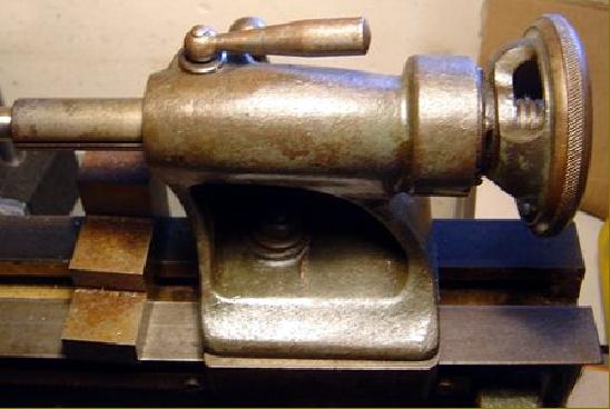
Model Engineer Magazine
- Percival Marshall
- M.E. History
- LittleLEC
- M.E. Clock

ME Workshop
- An Adcock
- & Shipley
- Horizontal
- Mill

Subscribe Now
- Great savings
- Delivered to your door

Pre-order your copy!
- Delivered to your doorstep!
- Free UK delivery!
All Forum Topics > Manual machine tools > Myford ML4 Restoration: Headstock bearings and spindle removal