Forum sponsored by:

Stuart Twin Victoria (Princess Royal) Mill Engine
| JasonB | 18/10/2022 13:16:06 |
 25215 forum posts 3105 photos 1 articles | Ah but did the museum just put it on planks? It's original working enviroment may have been different |
| Dr_GMJN | 18/10/2022 13:35:52 |
 1602 forum posts | Posted by JasonB on 18/10/2022 13:16:06:
Ah but did the museum just put it on planks? It's original working enviroment may have been different
Probably, but it's a fairly large working steam engine, bolted to a wood covered floor. Good enough for me! I was thinking of pasting brick paper around the inside of the wheel well to give a bit more interest too. I'll mess about with some CAD of different options, and might even try a small section of parquet flooring to see how it looks with the various features like Ramon's concrete MDF bases etc. I suppose I could get some 1" ply and make a temporary base for setting up. After all everything will need setting up again after painting. I can't finalise & paint the beds yet until I've figured out what holes will be needed for whatever cylinder drain pipework there will be.
|
| JasonB | 18/10/2022 13:47:57 |
25215 forum posts 3105 photos 1 articles | I suppose you could have a "screeded" area that extends out beyond the base of the machines and a flush parquet walkway around and between them which would reduce the amount of work needed but still allow you a timber floor. Add a few gridded panels to cover pipe runs and that could look quiet good. Also worth bearing in mind that what may look like floorboards in mill buildings were infact "board on edge" where you would have substantial say 4" x 12" boards stood on edge and butted up to each other for a solid floor. These fetch a premium now for resawing into floor boards. If you are going for paper bricks you can also get good looking A3 sheets of parquet too. Edited By JasonB on 18/10/2022 13:53:04 |
| roy entwistle | 18/10/2022 13:57:00 |
| 1716 forum posts | All due respects Dr. but a museum is not a working environment. Roy |
| Ramon Wilson | 18/10/2022 14:01:07 |
 1655 forum posts 617 photos | I can see your point Doc but even in a museum setting I would sincerely hope there was a very supportive foundation directly below those floor boards even if they are around 4-5inches thick. I would say that most full size engines of your build type were mounted on either concrete or stone block foundations which were usually, though not always, higher than the floor itself. Floor 'decoration' is another matter of course. Just had a quick look through a volume of the Textile Mill Engine which confirms this, some engines appearing to be directly mounted to the floor, others on 'plinths' of varying thickness. To my mind the plinth gives the engine another dimension so I've always done that. but it isn't something that's cast in stone (oops!) I'll look forward to seeing your result
R
|
| JasonB | 18/10/2022 14:09:52 |
25215 forum posts 3105 photos 1 articles | Though having just flicked through George Watkins' " the steam engine in industry" there are a few images in there of timber floors, plate 52 below would be closest to your engine.
I did put my Filer & Stowell engine onto a wooden floor as I found old B&W photos that showed this. However they were often use din timber mills in the US so far more likely to have had the buildings constructed of timber than here Edited By JasonB on 18/10/2022 14:14:07 Edited By JasonB on 18/10/2022 14:21:29 |
| Dr_GMJN | 18/10/2022 15:40:54 |
1602 forum posts | Thanks guys - I'll figure something out and see what it looks like. Roy - OK, the museum isn't a working environment, but the image Jason just posted appears to be? End of the day it's not a scale model of a specific engine, so if steam engines can be mounted on wood - or at least within a wooden floor environment - then why not do something a bit different? |
| Ramon Wilson | 18/10/2022 16:26:58 |
1655 forum posts 617 photos | Posted by Dr_GMJN on 18/10/2022 15:40:54:
Thanks guys - I'll figure something out and see what it looks like. Roy - OK, the museum isn't a working environment, but the image Jason just posted appears to be? End of the day it's not a scale model of a specific engine, so if steam engines can be mounted on wood - or at least within a wooden floor environment - then why not do something a bit different?
Doc, I quite agree for as though some of the larger engine houses show little evidence of wood flooring, quite a few of the smaller, such as the one in Jason's image, do. Albeit an engraving, here's a good example that might be worth considering - not 'parquet' I know but a lot less work involved
|
| JasonB | 18/10/2022 16:32:18 |
25215 forum posts 3105 photos 1 articles | I thought that was quite a large engine room as the flywheel is said to be 32ft dia and weighs 50T Photo of a similar engine to Ramon's 2nd illustration here
Edited By JasonB on 18/10/2022 16:35:09 |
| Ramon Wilson | 18/10/2022 18:03:52 |
1655 forum posts 617 photos | That's a cracking image Jason, don't suppose you have one of the valve side too. I wasn't referring to the engine but the room floor area which though long appears quite narrow - some of the rooms that housed twin engines appear quite massive in area by comparison. Whilst there may be the odd one or so I can't recall any examples of wood floors in the larger rooms in any of the Watkin books I have but it's been quite a while since I was gleaning images for detail from those. As you are aware, I thought for a while that Doc was wanting to replicate a full size engine. As the intention is to build a nice model based on full size then it comes down to 'beauty is in the eye of the beholder' and I'm sure we will see just that at journeys end. Regards - R
|
| JasonB | 18/10/2022 18:07:40 |
25215 forum posts 3105 photos 1 articles | Not one but two of the other side Edited By JasonB on 18/10/2022 18:09:15 |
| Ramon Wilson | 18/10/2022 19:12:54 |
1655 forum posts 617 photos | Thanks Jason, downloaded and saved
|
| Dr_GMJN | 18/10/2022 23:23:43 |
1602 forum posts | Ramon - the idea was/is to build the Proncess Royal version of the Twin Victoria, pretty much to the plans from the magazine. For a second model and with my limited experience I think it's about the right amount of scale detail; it was never going to be some kind of perfect replica. I'm all for trying to make a few minor embellishments like glass oilers etc, but I'm also fine with it being 'semi-scale', such as with the main bearings we discussed previously. I suppose that attitude might seem strange, but I think I'll be happy with it once it's complete. The parquet thing was just a whim, and since I've not seen it before on an engine model I thought I'd have a go. If it looks a bit naff I'll bin it and try something else - probably plain wood. BTW the very first thing I noticed at the Midlands show last Saturday was the Twin Victoria on the Stuart Moldels stand opposite the main entrance. I was surprised to see it fitted to two separate free-standing base blocks (at least I couldn't see that they were connected by anything other than the crankshaft). |
| Ramon Wilson | 19/10/2022 08:42:58 |
1655 forum posts 617 photos | Morning Doc, yes I do now realise that's how you see it, just that initially I thought your intention was to improve on the PR improvement so to speak. Even the basic Twin Vic is a nice model in it's own right so any embellishment however minor will improve matters. 'At the end of the day' the important matter is to enjoy what you do and how you do it. My input has always been based not on what you should do but what I have done and found to be the easiest to achieve an accurate result with minimal effort. I'd like to think that I have never made a comment on anything without previous experience of it and at times an example to show for it. Advice comes from different directions on any forum or indeed club room - but it's the individual that makes the choice and hopefully enjoys the process as a result. On that note your thoughts on a Parquet flooring may be a whim to some but it would certainly be an eye catcher from a display point of view. My thoughts are based on planking ships decks with similar width but much longer lengths of wood using cyano as said. I'm not sure I would want to tackle a parquet floor with CA as it can be difficult to control but I see no reason why (apart from its a big commitment) you should not give it a go. If you draw it out in Cad as you say with edging and all and place the model on top you'll soon get the idea of whether it's worth doing or not. Jasons idea of inserted areas of it is a good suggestion too. If you decide to go for plain wood may I suggest using lime - readily available in strips from various sources - an easy wood to work that takes a stain well and has a fine grain too - the latter being something to really consider from a scale effect point of view. I can't recall seeing the ST Twin Vic display model but to my mind a firm sub base on which to construct the model base is an absolute necessity - the firmer the better too as it's easy to wring something if not. Whether you then decide to put it on separate plinths is down to choice. Heres a top view of mine - main base is about 1" thick multi layer ply, a scrap piece I coined from somewhere - the plinths are MDF. Apart from the Corliss base which was a constructed affair all other engines have been on kitchen work top chip board with a hard wood border - very rigid.
All the best - R Edited By Ramon Wilson on 19/10/2022 08:45:49 |
| Dr_GMJN | 23/10/2022 00:33:20 |
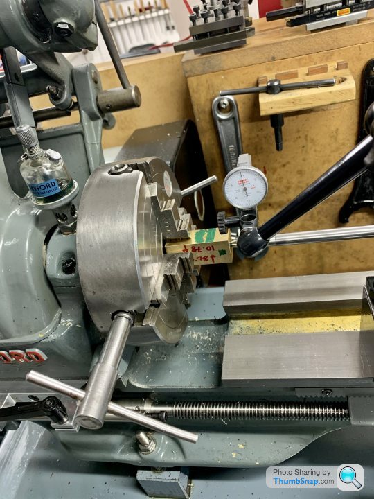
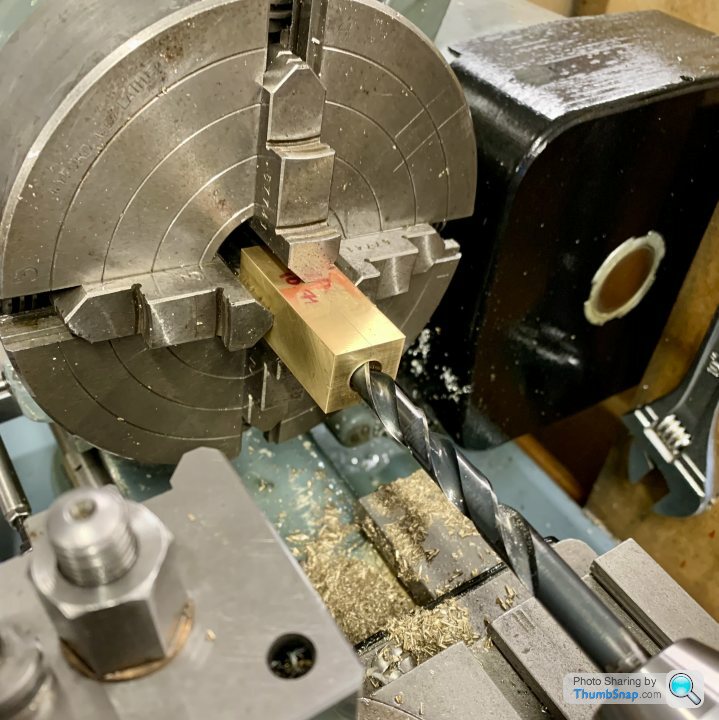
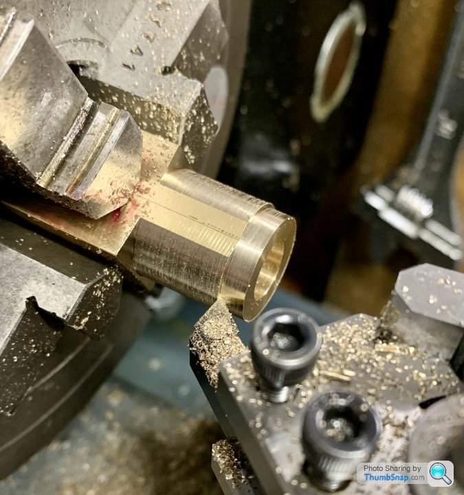
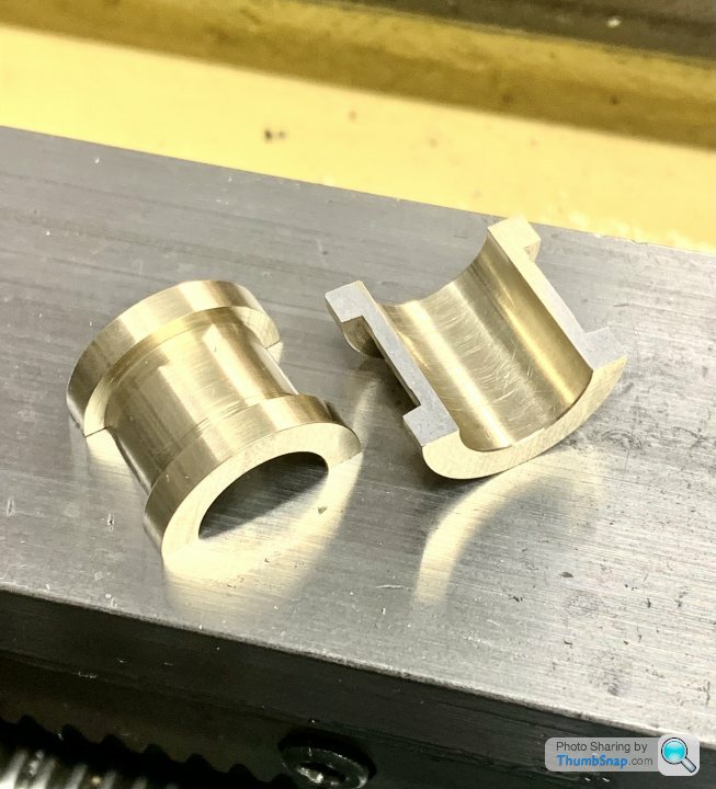
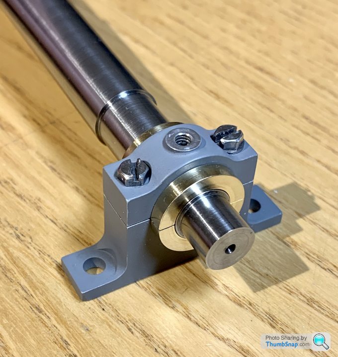
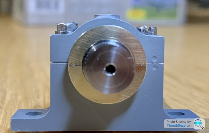
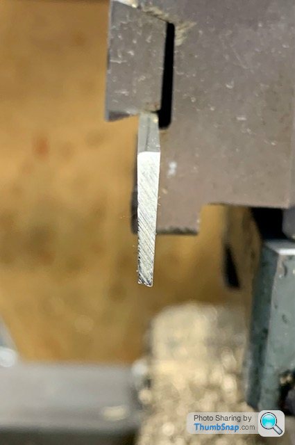
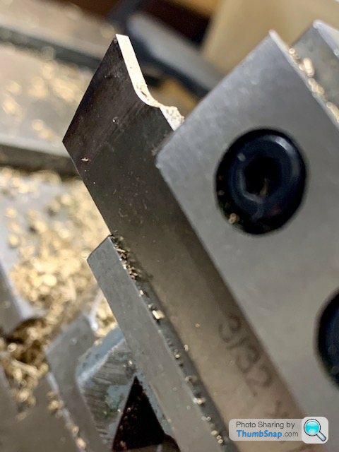
1602 forum posts | So today (actually yesterday at this time), I centre drilled the other end of the soldered brass bearing block, and did a few bits of lathe housekeeping ready for making the bearings. I can’t find Jason’s procedure, but I think I needed to use a thin parting tool to make the central groove where it fits into the housing. Question is how do I grind the steel tool exactly perpendicular? If the edge is slightly skewed, it’ll make a groove with a ridge at one end or the other. I’m concerned it won’t seat properly. Also, can you move a parting blade side-to-side to make continuous cuts? I also have an insert parting tool which I believe is deliberately skewed to aid break-through into a bore, or to form a point which breaks off when parting solid. Thanks. |
| JasonB | 23/10/2022 07:05:20 |
25215 forum posts 3105 photos 1 articles | Bottom of page If using your belt sander make a simple guide to keep it square, bit of MDF would do Other points covered in my post. |
| Dr_GMJN | 23/10/2022 10:09:06 |
1602 forum posts | Posted by JasonB on 23/10/2022 07:05:20:
Bottom of page If using your belt sander make a simple guide to keep it square, bit of MDF would do Other points covered in my post. Thanks Jason, so “feeding in and then traversing side to side”, to me that means I’m using the parting tool like a normal cutting tool, but wouldn’t that just bend the tool because there are no cutting edges at the side? Or do you mean feeding in to a set depth, moving out, stepping over then feeding in again? |
| JasonB | 23/10/2022 13:01:04 |
25215 forum posts 3105 photos 1 articles | Once most of the material has been removed by plunging the last few thou can be done by moving sideways but only advance the tool a thou or so at a time, the tool will cut it. If you are worried about leaving metal at the ends due to the grind of your tool a shallow 2-3 thou undercut can be used at either end. |
| Dr_GMJN | 23/10/2022 21:39:07 |
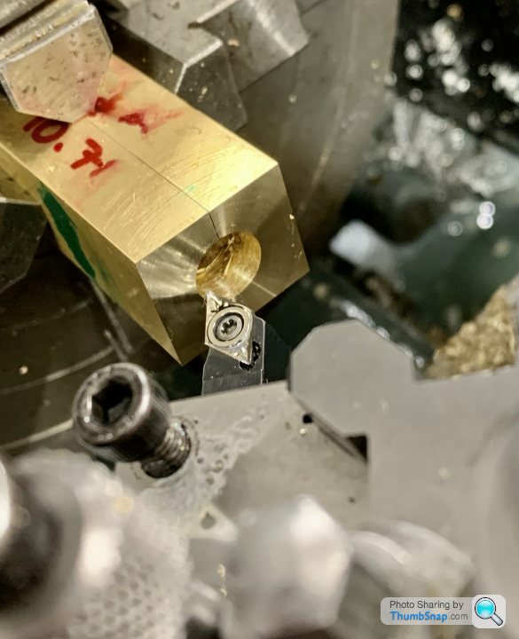
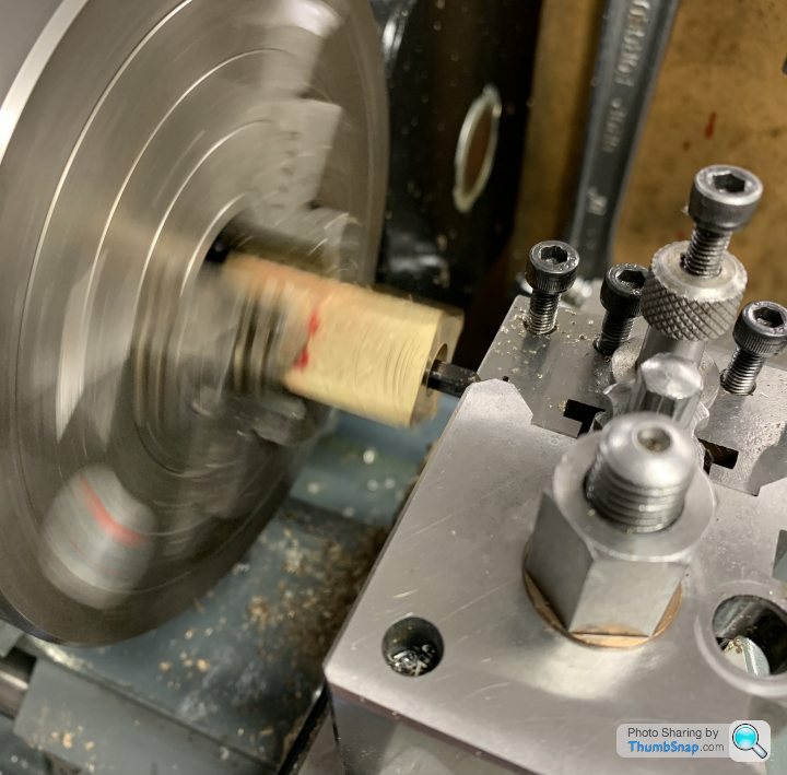
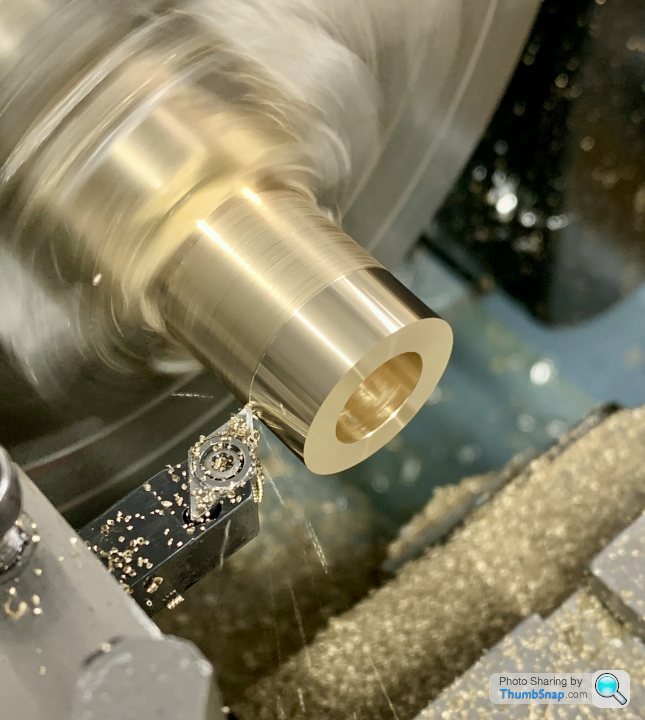
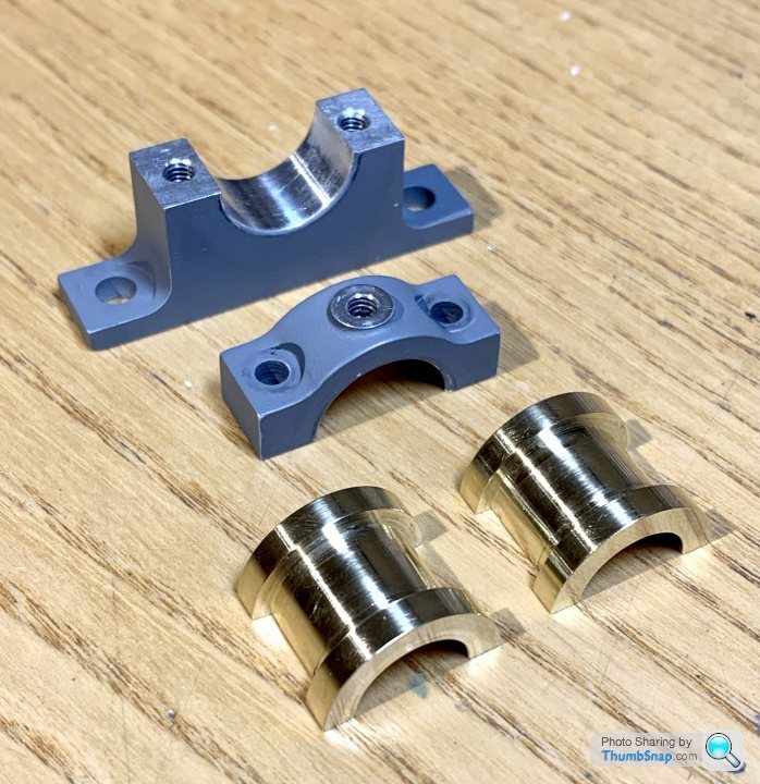
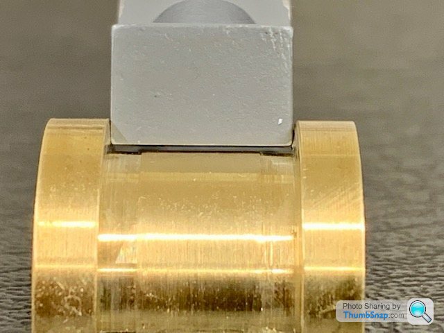
1602 forum posts | Made a start. |
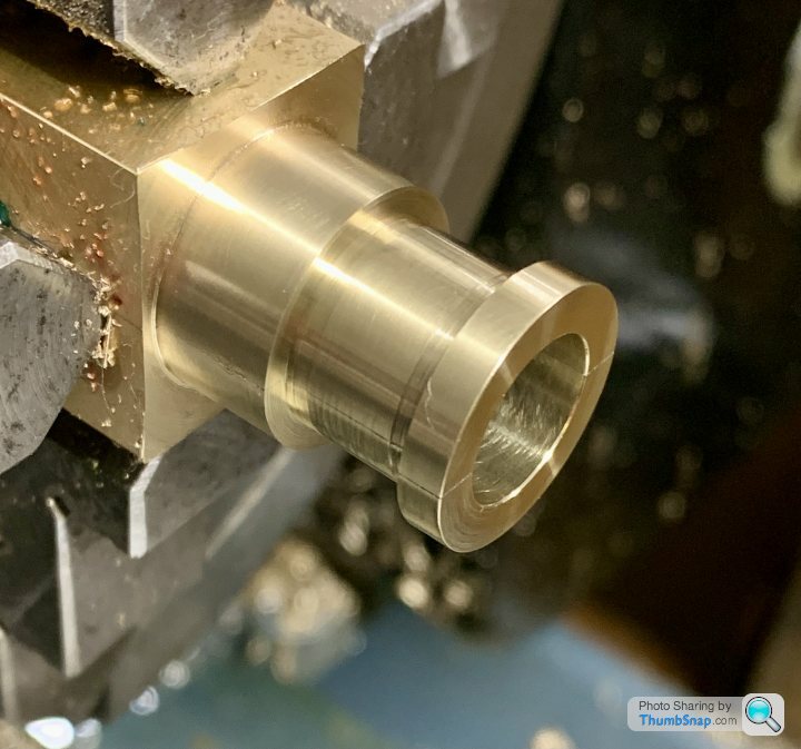
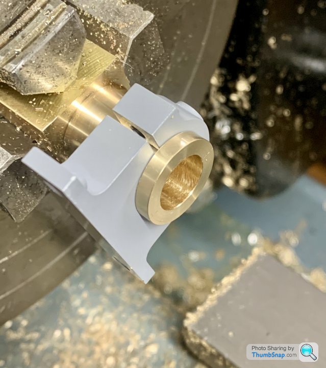
| Dr_GMJN | 26/10/2022 22:39:38 |
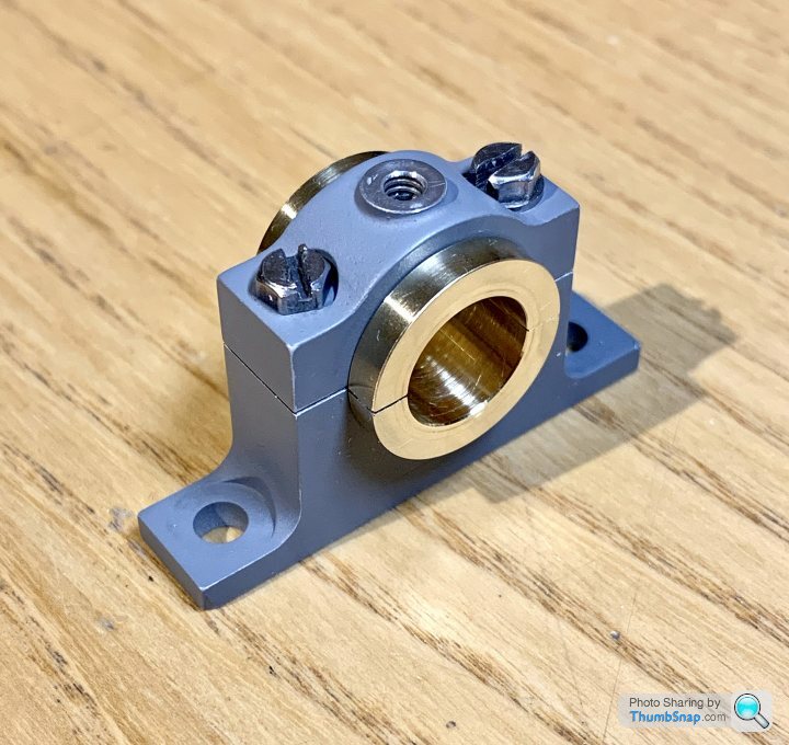
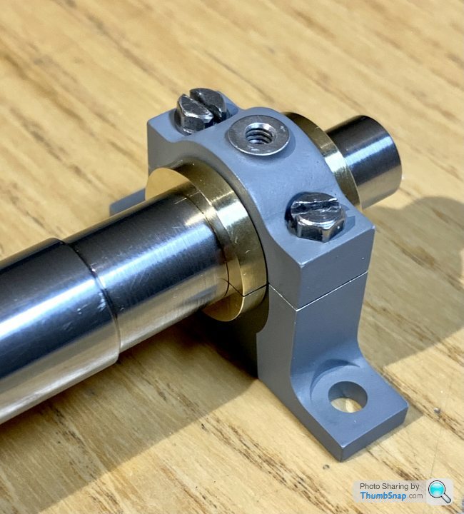
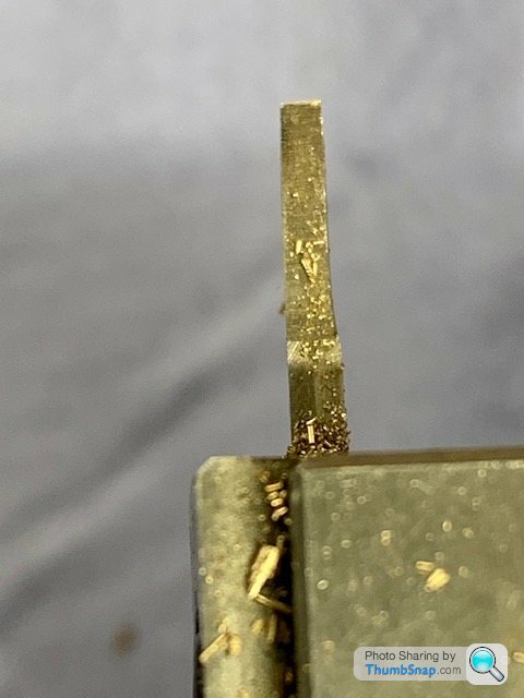
1602 forum posts | Hmm I thought there was something not quite right when I was test fitting and reducing the bearing diameters - it seemed like even though I was taking more off the inner flanks, it wasn't making a proportional difference to the fit. Eventually, despite finding it difficult to get consistent vernier readings (for obvious reasons now) they seemed to be a perfect fit, so I carried on. |


Please login to post a reply.
Magazine Locator
Want the latest issue of Model Engineer or Model Engineers' Workshop? Use our magazine locator links to find your nearest stockist!
Sign up to our Newsletter
Sign up to our newsletter and get a free digital issue.
You can unsubscribe at anytime. View our privacy policy at www.mortons.co.uk/privacy
Latest Forum Posts
- hemingway ball turner
04/07/2025 14:40:26 - *Oct 2023: FORUM MIGRATION TIMELINE*
05/10/2023 07:57:11 - Making ER11 collet chuck
05/10/2023 07:56:24 - What did you do today? 2023
05/10/2023 07:25:01 - Orrery
05/10/2023 06:00:41 - Wera hand-tools
05/10/2023 05:47:07 - New member
05/10/2023 04:40:11 - Problems with external pot on at1 vfd
05/10/2023 00:06:32 - Drain plug
04/10/2023 23:36:17 - digi phase converter for 10 machines.....
04/10/2023 23:13:48 - More Latest Posts...
- View All Topics
Support Our Partners


Shopping Partners
Subscription Offer

Latest "For Sale" Ads
- Reeves** - Rebuilt Royal Scot by Martin Evans
by John Broughton
£300.00 - BRITANNIA 5" GAUGE James Perrier
by Jon Seabright 1
£2,500.00 - Drill Grinder - for restoration
by Nigel Graham 2
£0.00 - WARCO WM18 MILLING MACHINE
by Alex Chudley
£1,200.00 - MYFORD SUPER 7 LATHE
by Alex Chudley
£2,000.00 - More "For Sale" Ads...
Latest "Wanted" Ads
- D1-3 backplate
by Michael Horley
Price Not Specified - fixed steady for a Colchester bantam mark1 800
by George Jervis
Price Not Specified - lbsc pansy
by JACK SIDEBOTHAM
Price Not Specified - Pratt Burnerd multifit chuck key.
by Tim Riome
Price Not Specified - BANDSAW BLADE WELDER
by HUGH
Price Not Specified - More "Wanted" Ads...
Get In Touch!
Do you want to contact the Model Engineer and Model Engineers' Workshop team?
You can contact us by phone, mail or email about the magazines including becoming a contributor, submitting reader's letters or making queries about articles. You can also get in touch about this website, advertising or other general issues.
Click THIS LINK for full contact details.
For subscription issues please see THIS LINK.
Digital Back Issues


Donate

 Register
 Log-in
Model Engineer Magazine
- Percival Marshall
- M.E. History
- LittleLEC
- M.E. Clock

ME Workshop
- An Adcock
- & Shipley
- Horizontal
- Mill

Subscribe Now
- Great savings
- Delivered to your door

Pre-order your copy!
- Delivered to your doorstep!
- Free UK delivery!
All Forum Topics > Work In Progress and completed items > Stuart Twin Victoria (Princess Royal) Mill Engine