Forum sponsored by:

Stuart Twin Victoria (Princess Royal) Mill Engine
| Dr_GMJN | 19/12/2020 16:21:32 |
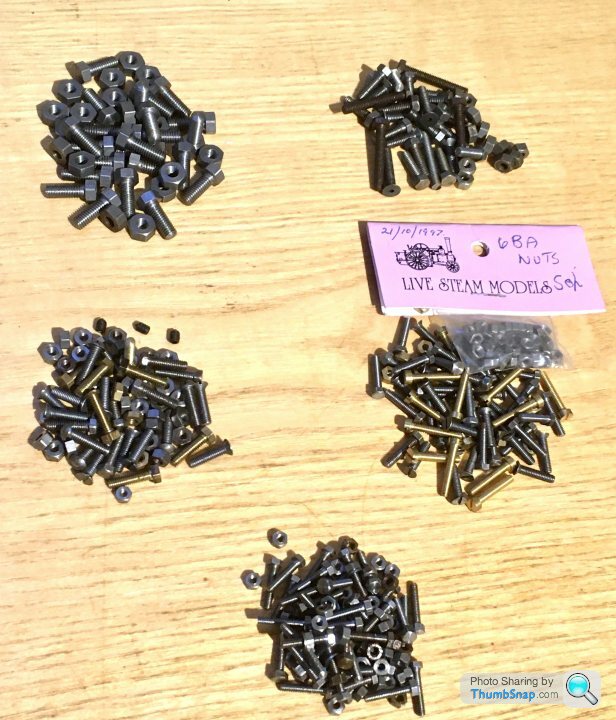
 1602 forum posts | Nice little parcel arrived today from some kind person over on the PH forum - some BA fasteners that they had spare: I suppose I should start sorting out my nuts and bolt storage boxes again - they have got into a bit of a state over the years... |
| Dr_GMJN | 27/12/2020 12:00:16 |
1602 forum posts | I had chance to look at the cylnder castings more closely yesterday. They are much longer than the 10V, so I now appreciate why using a boring bar between centres is the way to go: Not only would the cylinders would be awkward to hold in any of the chucks I have, my largest boring bar would be pretty flexible at the extension from the tool holder I'd need. |
| Dr_GMJN | 29/12/2020 20:35:15 |
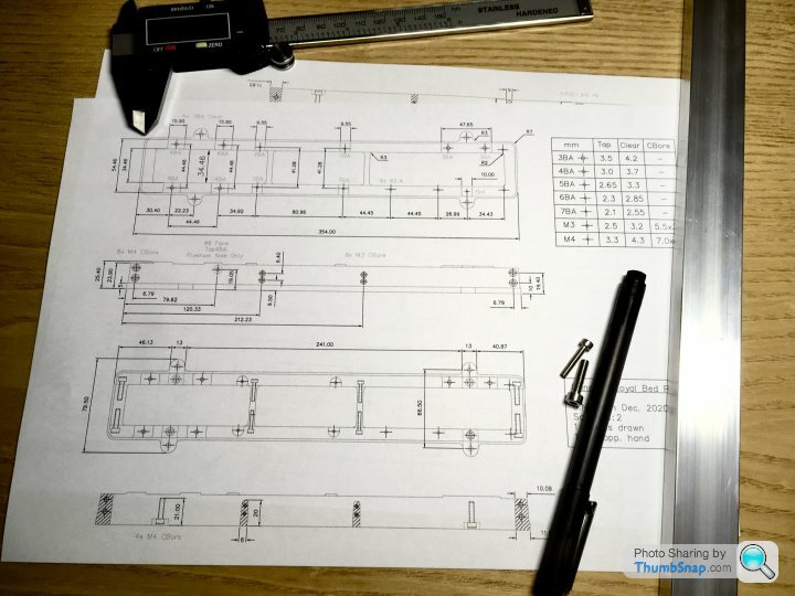
1602 forum posts | Got the fabricated bed drawings done - not quite to BS8888, and the check and approve process was a bit sketchy, but still: |
| Dr_GMJN | 31/01/2021 15:11:36 |
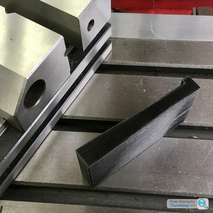
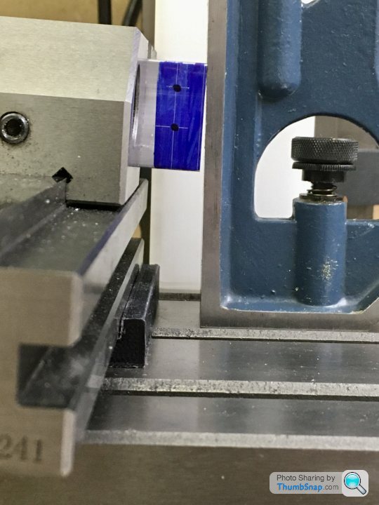
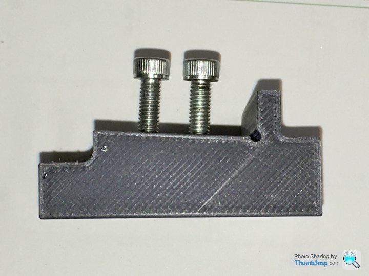
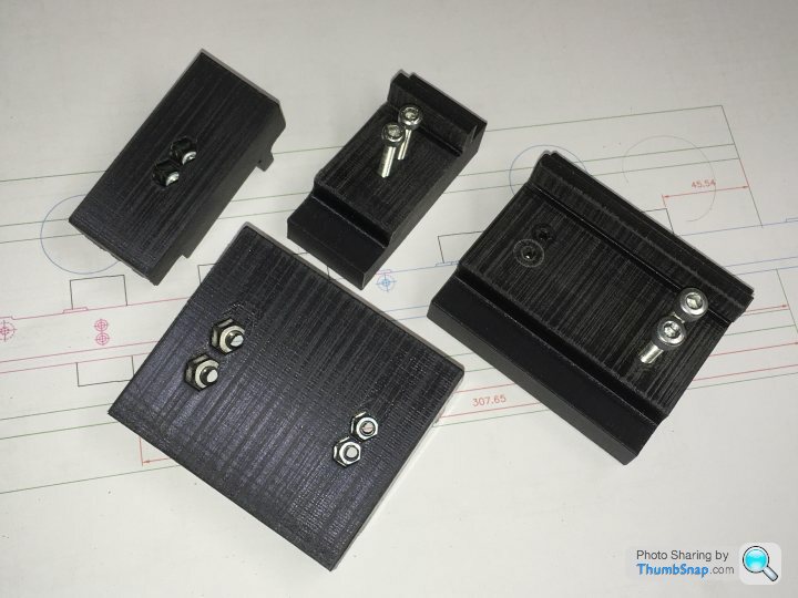
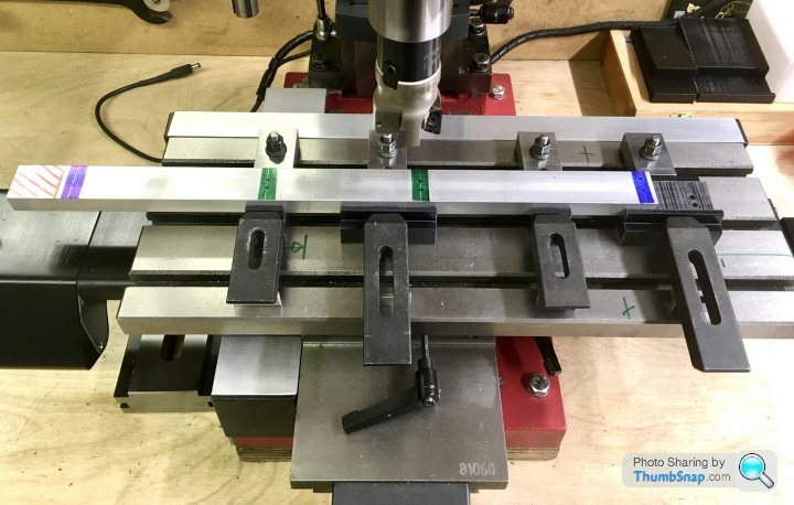
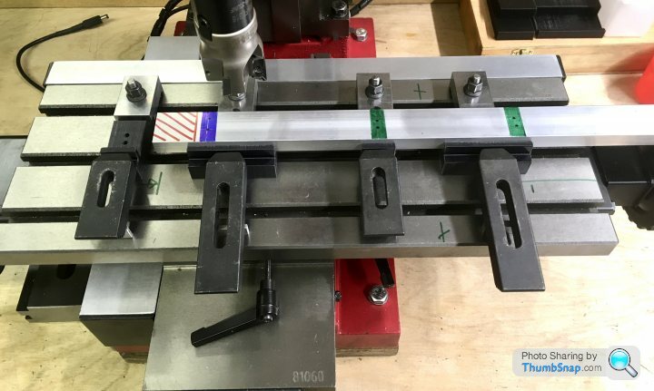
1602 forum posts | Still too cold to do anything significant in the garage, so I thought I'd at least make some jigs to help get the tapers on the simulated bed castings right. |
| Ramon Wilson | 01/02/2021 08:13:07 |
 1655 forum posts 617 photos | Some nice thinking there Doc - I like the printed support blocks. Not familiar with 3D printing I assume the material must be of suitable resistance/hardness. Getting confused over mirror images is my forte - just had a session myself with a R/H pocket ending up in a L/H spot! Thank goodness for JB Weld though Good to see you've made a tentative start - it'll soon warm up in that garage
Ramon |
| Dr_GMJN | 01/02/2021 10:19:07 |
1602 forum posts | Posted by Ramon Wilson on 01/02/2021 08:13:07:
Some nice thinking there Doc - I like the printed support blocks. Not familiar with 3D printing I assume the material must be of suitable resistance/hardness. Getting confused over mirror images is my forte - just had a session myself with a R/H pocket ending up in a L/H spot! Thank goodness for JB Weld though Good to see you've made a tentative start - it'll soon warm up in that garage
Ramon
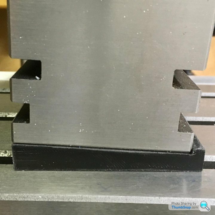
Thanks Ramon. The blocks are printed in PLA - it's a bit like nylon. I gave it a 50% solid honeycomb internal fill. It's way stiff enough in compression for this application. I printed them on their ends so that the profile has maximum accuracy. In this case though, accuracy isn't as important, as repeatability in that so long as when I put subsequent bars in the jig they all come out at the same angle. Yes, I've already confused myself with left and right hands for this. I think another two of the large blocks are needed, but of the opposite hand. I'll still probably get it wrong, which is why I'm using non-workshop time to try and figure it all out on CAD and write the sequence down! |
| Dr_GMJN | 28/02/2021 20:29:45 |
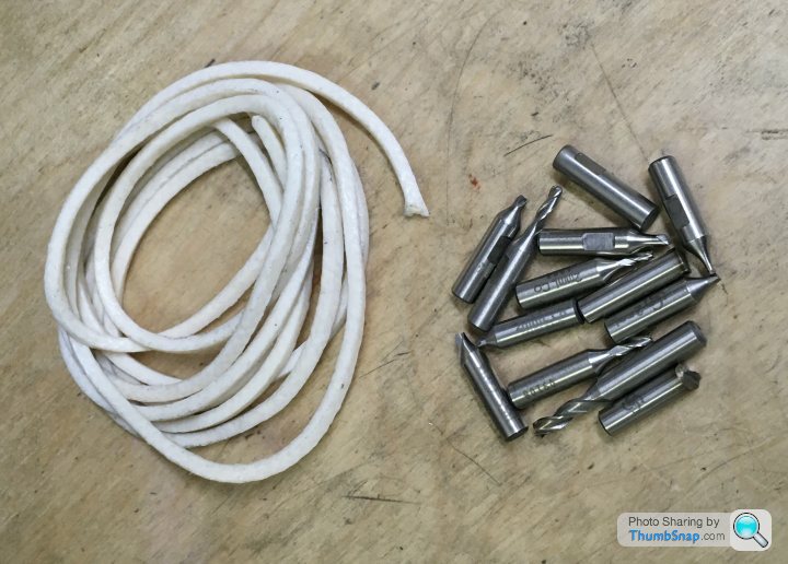
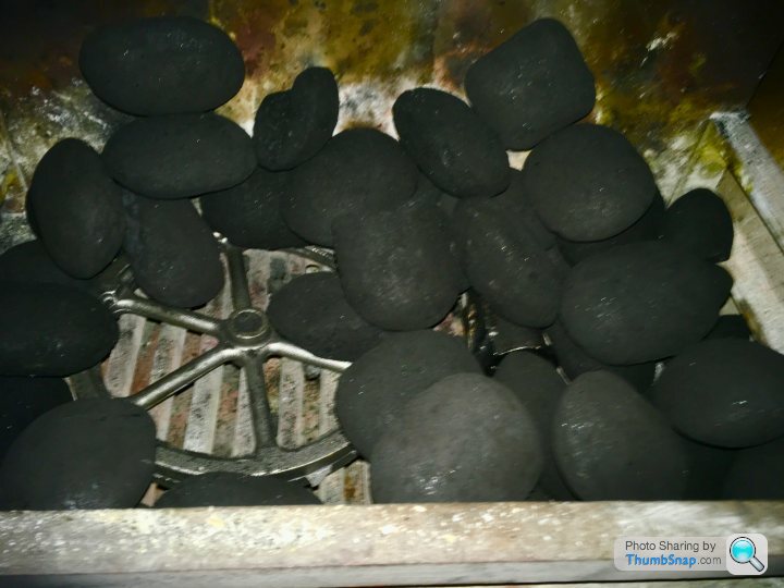
1602 forum posts | All, I've read a couple of times people suggesting putting black castings into an open fire and leaving them overnight, to soften them. I didn't have much issue with chilled castings on the 10V, although there were some areas that looked distinctly different shades after machining. Is it worth doing this? I'm just thinking it's getting to the time of year when we'll not be having many more fires, so thought I'd shove them in there next time. If it's worth doing, is there a risk of melting them? I doubt it, because after all the grate doesn't melt. We're using smokeless fuel on an open fire. Also, is there a set amount of time to leave them in there? Next question is on the between centres boring bar (again). What should the cutter geometry have, and can I do it on a rough grinding wheel, and finish it on the belt sander? Never done tool grinding before, and would rather avoid it altogether, but it seems like I need to learn it sooner or later. I hope I don't damage a casting; presumably if its ground wrong it'll be immediately obvious that something is amiss? Thanks! |
| JasonB | 28/02/2021 20:42:43 |
 25215 forum posts 3105 photos 1 articles | You have nothing to loose so chuck them in the fire to cook for the evening and leave in the ashes overnight. You can use an old file to see if any corners of thin sections are hard as it will just skate off the metal if they are. You can do it all on the grinding wheel but nothing wrong with finishing on a belt sander. I'll see if I can dig out a picture, think there are some in an album. EDIT, half way down the 4th line of images in this album there are 5 showing a suitable boring bar tool. Edited By JasonB on 28/02/2021 20:45:30 |
| Dr_GMJN | 28/02/2021 21:37:13 |
1602 forum posts | Posted by JasonB on 28/02/2021 20:42:43:
You have nothing to loose so chuck them in the fire to cook for the evening and leave in the ashes overnight. You can use an old file to see if any corners of thin sections are hard as it will just skate off the metal if they are. You can do it all on the grinding wheel but nothing wrong with finishing on a belt sander. I'll see if I can dig out a picture, think there are some in an album. EDIT, half way down the 4th line of images in this album there are 5 showing a suitable boring bar tool. Edited By JasonB on 28/02/2021 20:45:30
Great, thanks. |
| Dr_GMJN | 03/03/2021 20:53:28 |
1602 forum posts | Cylinder lagging covers, or not? I do like the clean look of covers, then again the castings are OK as well on these. Can’t see any images of them with covers. Any comments? Personal preference or would it be one or the other on the real thing? Id want to plan the cylinder cap diameters and fettle the casting ends to form the right recess depth before making a start if covers are to be fitted. |
| Ramon Wilson | 03/03/2021 22:49:33 |
1655 forum posts 617 photos | Hello Doc G If you are making something to represent a mill engine as PR does then you really need to lag the cylinders. Only a lot older and much smaller engines would have unlagged cylinders. I use tempered spring steel sheet which is easily worked and drilled. Colour can be done either in an oven if the temp will reach 280 plus or by laying in hot dry sand though the latter can be a bit too quick to change if you aren't ready for it. The sand needs to be hot before you introduce the lagging. Also - if using very small brass BA screws (14/16 BA) as fasteners - it's a lot less stressful to drill and tap small individual brass inserts in the lathe and fit them to suitable holes in the casting rather than drilling and tapping the casting itself.
Edited By Ramon Wilson on 03/03/2021 22:50:58 |
| JasonB | 04/03/2021 07:06:28 |
25215 forum posts 3105 photos 1 articles | I've found thin aluminium works well as cladding and is easier to work with. Or if you want timber then thin strips glued to linen makes it a lot easier to handle as one sheet rather than loose strips and can be cut to a card template |
| Dr_GMJN | 04/03/2021 07:57:10 |
1602 forum posts | Thanks both. I like the clean look of aluminium, and it’s easy to work as Jason says. Would it be secured with a few screws around the cylinder end bosses in this case, or with screws underneath that are hidden? Might look a bit fussy with former. Thanks. |
| JasonB | 04/03/2021 08:05:18 |
25215 forum posts 3105 photos 1 articles | You need to think what access they had on the original. easy enough for us to turn the model upside down to get at hidden screws but full size they would have needed to get to them. Probably a screw where the round end of the flange meets the vertical face of the steam passage. Just 4 of those if you want to do it as a single sheet but full size would most likely had one sheet each side so you need screws down towards the bottom of the flanges too. |
| Ramon Wilson | 04/03/2021 08:28:43 |
1655 forum posts 617 photos | Nothing wrong with using aluminium save one thing - impossible to get a colour on it as on steel. There was coloured ali available but to me it does not have the same look as steel - depends on how you see the finished model representing full size. Tempered shim steel is relatively easy to work - I use a ground hacksaw blade to scribe (score) and gently bend to break along a line. It can also be cut with a jewellers saw filed and drilled without issues and even milled if held down properly - clamped between two sacrificial pieces of ali or steel. I made the lagging in one piece held with small section brass strips at the top edge.
|
| JasonB | 04/03/2021 08:46:55 |
25215 forum posts 3105 photos 1 articles | I think you will have to do it in two pieces as the modified cylinder "feet" will not allow a single sheet to be wrapped around the cylinder so maybe something line this (feet not shown)
|
| Ramon Wilson | 04/03/2021 09:00:10 |
1655 forum posts 617 photos | Ah, I'd overlooked the feet modification Jason - I think I'd be inclined to do it as two halves though with the split line along the length underneath with cut outs to clear the feet.
|
| Dr_GMJN | 04/03/2021 17:23:03 |
1602 forum posts | Yep, OK both I like the look of that. On the 10V, the anodised aluminium was damaged, so after cutting and drilling it to fit, I sprayed it with Satin Black. I was in two minds whether to get another piece, but in the end concluded I would only scratch it at some point. It looked ok in the end. Thanks. |
| Dr_GMJN | 05/03/2021 17:22:39 |
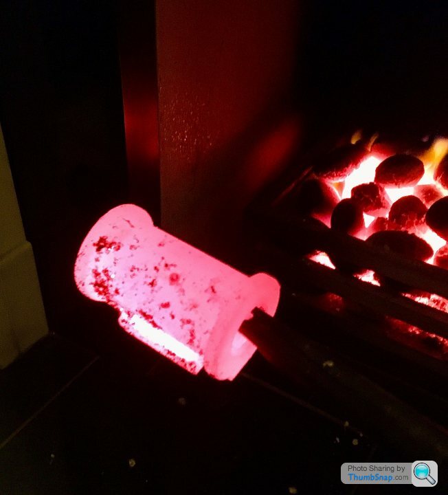
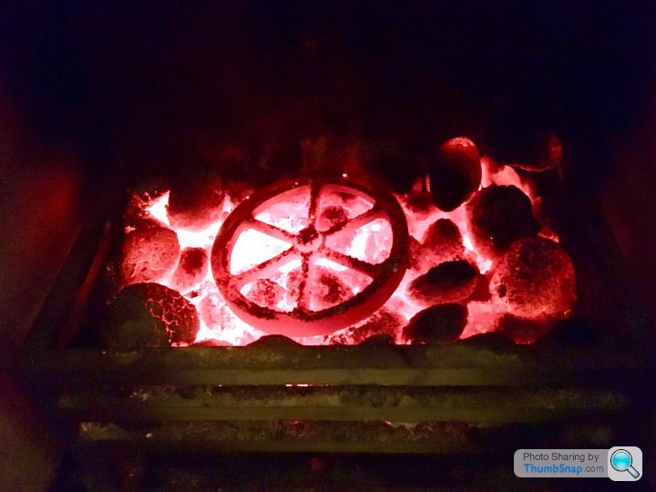
1602 forum posts | I hope this doesn't turn out to be an expensive experiment... |
| Dr_GMJN | 05/03/2021 23:49:18 |
1602 forum posts | let’s see what they look like in the morning...had a poke about with them earlier when they were at their hottest, and they still seemed ok. |


Please login to post a reply.
Magazine Locator
Want the latest issue of Model Engineer or Model Engineers' Workshop? Use our magazine locator links to find your nearest stockist!
Sign up to our Newsletter
Sign up to our newsletter and get a free digital issue.
You can unsubscribe at anytime. View our privacy policy at www.mortons.co.uk/privacy
Latest Forum Posts
- *Oct 2023: FORUM MIGRATION TIMELINE*
05/10/2023 07:57:11 - Making ER11 collet chuck
05/10/2023 07:56:24 - What did you do today? 2023
05/10/2023 07:25:01 - Orrery
05/10/2023 06:00:41 - Wera hand-tools
05/10/2023 05:47:07 - New member
05/10/2023 04:40:11 - Problems with external pot on at1 vfd
05/10/2023 00:06:32 - Drain plug
04/10/2023 23:36:17 - digi phase converter for 10 machines.....
04/10/2023 23:13:48 - Winter Storage Of Locomotives
04/10/2023 21:02:11 - More Latest Posts...
- View All Topics
Support Our Partners


Shopping Partners
Subscription Offer

Latest "For Sale" Ads
- Reeves** - Rebuilt Royal Scot by Martin Evans
by John Broughton
£300.00 - BRITANNIA 5" GAUGE James Perrier
by Jon Seabright 1
£2,500.00 - Drill Grinder - for restoration
by Nigel Graham 2
£0.00 - WARCO WM18 MILLING MACHINE
by Alex Chudley
£1,200.00 - MYFORD SUPER 7 LATHE
by Alex Chudley
£2,000.00 - More "For Sale" Ads...
Latest "Wanted" Ads
- D1-3 backplate
by Michael Horley
Price Not Specified - fixed steady for a Colchester bantam mark1 800
by George Jervis
Price Not Specified - lbsc pansy
by JACK SIDEBOTHAM
Price Not Specified - Pratt Burnerd multifit chuck key.
by Tim Riome
Price Not Specified - BANDSAW BLADE WELDER
by HUGH
Price Not Specified - More "Wanted" Ads...
Get In Touch!
Do you want to contact the Model Engineer and Model Engineers' Workshop team?
You can contact us by phone, mail or email about the magazines including becoming a contributor, submitting reader's letters or making queries about articles. You can also get in touch about this website, advertising or other general issues.
Click THIS LINK for full contact details.
For subscription issues please see THIS LINK.
Digital Back Issues


Donate

 Register
 Log-in
Model Engineer Magazine
- Percival Marshall
- M.E. History
- LittleLEC
- M.E. Clock

ME Workshop
- An Adcock
- & Shipley
- Horizontal
- Mill

Subscribe Now
- Great savings
- Delivered to your door

Pre-order your copy!
- Delivered to your doorstep!
- Free UK delivery!
All Forum Topics > Work In Progress and completed items > Stuart Twin Victoria (Princess Royal) Mill Engine