Forum sponsored by:

Stuart Twin Victoria: Advice & General Questions
| JasonB | 23/10/2020 09:32:52 |
 25215 forum posts 3105 photos 1 articles | You have got it easy Andrew with a factor of 27, if we take the height of an average handrail as 36" and the ones on Princess Royal stand 2" tall that makes for a 1/18th scale model so the factor is 5700! No wonder the governor scales out at 6ft tall with what would be 9" dia balls. |
| Andrew Johnston | 23/10/2020 12:11:16 |
 7061 forum posts 719 photos | Well if you will persist with all this tiddly stuff what do you expect? I build big stuff as an antidote to work electronics. The current job is going to require using ICs that are 0.8mm square with 4 solder balls underneath on a 0.4mm pitch. For space reasons we will need to use 0201 passives; that's 20 thou by 10 thou. I can't even see the darn things without a magnifier. Andrew |
| Andrew Johnston | 23/10/2020 12:25:36 |
7061 forum posts 719 photos | I use insert tooling for general turning but use a lot of HSS tooling for specials. On the repetition lathe I exclusively use HSS toolbits as that is what it was designed to use. The internal grooves in these eccentric straps were machined with a HSS tool using the numbers on the dials rather than measure and cut:
Likewise the mating sheaves were machined with a HSS tool:
I used a groove micrometer as a sanity check on the groove widths. Like Ramon I make one off tooling using silver steel and gauge plate:
If I've done it then I'm happy to explain how, if I haven't then I keep quiet. Andrew |
| JasonB | 23/10/2020 13:07:29 |
25215 forum posts 3105 photos 1 articles | Posted by Andrew Johnston on 23/10/2020 12:11:16:
Well if you will persist with all this tiddly stuff what do you expect? Andrew Ah, I forgot you were back Andrew and should have put "approx" as I used 0.056 as 1/18th Rather you than me on the soldering I did have a bit of a doodle last night, Vicky and her twin sister in the early stages, all fabricated.
|
| Dr_GMJN | 23/10/2020 13:29:51 |
 1602 forum posts | That looks good Jason. The difference I have is mainly in the bearing mounts. I've been quoted for 25mm x 10mm Al. I was thinking to have an 8 mm high parallel side around the base at 10 mm wide, a 15 mm high tapered section above that, then another 2 mm high parallel section at 9.53 mm, which would match the 3/8" wide bearing blocks. This 2 mm high section would be milled back along the lengths to form the bearing and cylinder mounting pads. By my reckoning this would then give an approx. 1.8 degree taper on the outside faces to represent some draw. I would have to figure out how to cut this angle accurately though. However, I do like the look of the plinth around the base - and how you've modelled it in general. I like the idea of not having mounting lugs, which look out of scale and a bit ugly. Is the intention on yours to use studs up through from the base and put nuts on the top? Thanks.
|
| JasonB | 23/10/2020 13:46:30 |
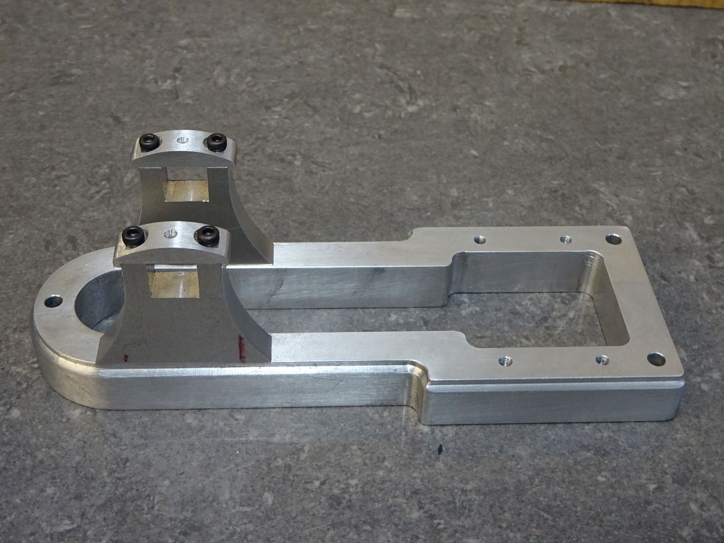
25215 forum posts 3105 photos 1 articles | I'd based my drawing on being able to pick up some imperial 1/2" x 1" aluminium and that would give me a 10mm width at the top allowing for draft and the flaired foot. Another option if you can't get that size or a slightly thicker metric one is to use a separate plate on the bottom as shown here (CNC not required) or rather than having the moulding at the bottom it can be cut into the top outer corner with a simple home made cutter.
Yes the base would be held down by long studs into the base with nuts bearing on raised round bosses. These bosses are just thick "washers" that are loctited into a shallow counterbore and then a fillet of filler run around the edge to give the cast look. |
| Dr_GMJN | 23/10/2020 16:32:11 |
1602 forum posts | OK so I can get 1” x 1/2” aluminium. I wonder if I could use the fly cutter with a 0.8mm tip radius insert to simultaneously form the angled side, and the step with its corner fillet? I might be able to make an angled jig out of steel, and secure the aluminium to it with screws through the steel into the Inner (flat) faces of it. |
| JasonB | 23/10/2020 19:14:47 |
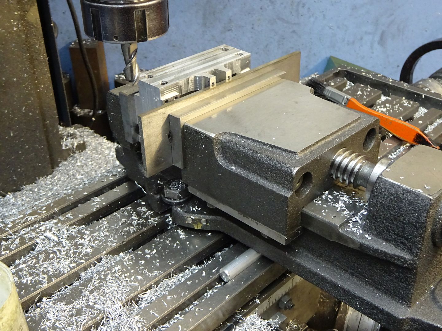
25215 forum posts 3105 photos 1 articles | Flycutter will do the sides easily but nay be a bit harder to set up for the ends, probably have to do the end pieces before assembly and sort out a way to the the ends of the sides then a final file all 3 pieces flush after the JB weld has gone off. Did I show the simple way to angle a vice for this sort of job? easy to work out height of packing if you know angle and distance between points of contact.
|
| Dr_GMJN | 23/10/2020 19:42:29 |
1602 forum posts | Yes, my intention was to taper all the parts separately and then assemble and file/fill as necessary. My vice isnt that wide, so I actually thought the long sides would be an issue with the ends deflecting. Hence the steel backing idea. One thing my supplier can’t get is crankshaft material : 7/16” diameter in a steel I’ll be able to cut a keyway in. I don’t really want to turn bar down for it. Any suggestions on type? Maybe something that’s ground or at least made to decent enough tolerances? Thanks.
|
| JasonB | 23/10/2020 19:55:04 |
25215 forum posts 3105 photos 1 articles | Precision Ground Mild steel has a similar finish and size tolerance to silver steel and is easier to work, M-Machine list it in 7/16" and go to the trouble to wrap it so not damaged by other materials in the same order. |
| Dr_GMJN | 23/10/2020 20:14:40 |
1602 forum posts | Posted by JasonB on 23/10/2020 19:55:04:
Precision Ground Mild steel has a similar finish and size tolerance to silver steel and is easier to work, M-Machine list it in 7/16" and go to the trouble to wrap it so not damaged by other materials in the same order. I’ll order some next week along with the rest. Looks like I might make a start a lot sooner than I thought. |
| Dr_GMJN | 24/10/2020 15:45:28 |
1602 forum posts |
So this morning I had a play about with fly-cutting some scrap aluminium. |
| JasonB | 24/10/2020 20:02:06 |
25215 forum posts 3105 photos 1 articles | You should be able to move the side along in the vice and go at it in two or three stages, I've certainly dome long items like that. I went with a larger 1.5mm radius and to give the 10mm width at the top that I'm using the angle comes out at just under 4deg
It's not too hard to grind up a round nosed tool bit to go into a small flycutter, another option is to freehand grind the corners of a blunt milling cutter to the radius you want. Does not have to be bang on as after all we are trying to replicate castings that are not perfect so a bit of hand work is a good thing that is why I usually nock off the external corners with a file rather than going for the more regular finish that a corner rounding milling cutter gives and will also run a Dremel over the surface for a bit of texture depending on scale. I should really be directing you to a copy of my book but here are a couple of examples of mouldings produced from basic freehand ground tools.
I would get all the parts to length first, drill and tap the ends of the four cross pieces and also drill and counterbore the sides first. Then setup to mill the long pieces to profile followed by the end pieces which can be done the same way. Then JBWeld and screw it together on a flat surface such as the mill table - a sheet of thin plastic cut from a bag will stop the work getting stuck to the mill table. Once the JBW has gone off (at least 24hrs) skim the bottom and then the top, while setup for the top you can reduce heights to leave the mounting bosses and drill & tap those. Also if using through studs for mounting these can be drilled and a counterbore added for the round bosses. Lastly hold by the sides in the vice at a slight angle so that most of the protruding ends of the side pieces can be side milled off then finish with a chalked file. lastly ease all external corners that would have been cast with file then Emery cloth. Before painting fill assemble screw holes with filler and add any internal fillets with filler or two part putty. |
| Dr_GMJN | 24/10/2020 20:32:58 |
1602 forum posts | Thanks Jason. Moving in the vice sounds like a plan. So were inevitably back to grinding tools! It’s something that seems a black art, and it genuinely makes me reluctant to have a go. I have tried it, with little success. Maybe I need a new type of bench grinder wheel. I know there are pages of advice in books and online, but whenever I try it...something’s been wrong somewhere! |
| Dr_GMJN | 24/10/2020 22:44:10 |
1602 forum posts | I’m re-reading the articles in more detail, and I’ve a question about connecting rods: In Part VI - “Connecting Rods”, It says I need two pieces of 3/8 in. x 5/16 in. mild steel, each about 6 1/4 in. long” It then goes on to detail how to turn this to form the round connecting rod, with rectangular ends. It mentions fitting a carrier. I think this is for turning between centres? Why would you do this if one end could be secured in the 4-jaw chuck (as outlined beforehand in order to centre drill both ends of the rectangular section)? I can’t think it’s for accuracy or repeatability, because firstly you’ve just used the 4-jaw to centre-drill the ends, so the centre drillings themselves are only as accurate as the 4-jaw setup, and once machined there’s no need to ever put it back in the lathe; in fact you’re going to file one of the centre marks away to form the rounded end at one side. I’ll do it as per the instructions, but I’m just wondering what the thinking is behind the process. Thanks.
|
| Ramon Wilson | 24/10/2020 23:00:27 |
 1655 forum posts 617 photos | Did you not see my last post Doc - last post on page 3? A good bench grinder is essential - minimum of 6" wheels for shaping. I have an 8" for that and a small Slibette 5" for tweaking the cutting point. As said I have used HSS for many years but only worry about the very point that cuts the metal - the rest of the shape is unimportant as long as there is clearance. Heres an example of a very effecient boring bar made from a redundant slot drill in a mild steel holder - 4BA screw. Doesn't look pretty but works perfectly.
And another using the shank of an FC3 throw away cutter (very high quality HSS for this purpose) ground into a parting tool for doing deep fins on an IC engine. Similar tool holder - other end)
Ideal for radii, screw cuttting, parting etc etc the limit of this tooling is your imagination - I have tin full of these little shanks ground into all sorts of shapes that get 'retuned' as required. You don't need a vast collection of expensive (relatively) HSS square blanks. Depends on what you want out of it - nice tooling to sit on the bench and look good when you're not using it or something that doesn't but does do the job exactly as you want. Grinding tools is not a black art but it does take practice - the more you do the easier it gets and the better you get at it. Unless you try though you won't know. Grinding square blanks with precise clearance angles is just not important. As long as the tool has enough clearance on the three faces then all that is required to get right it just that part that does the cutting. If you don't get it quite right for the material - eg a poor finish, chatter etc then it's just a matter of a slight tweak at the point to find what does. Obviously a knowledge of the basics of cutting angles for varying materials is required but they don't have to be precise all over. It's easy to get bogged down on thinking that expensive inserted tooling is required to achieve a good result -especially expensive if you need something for just one job - but in my opinion nothing beats a freshly ground HSS tool and especially so if you are machining brass/bronze/gunmetal. Ramon Edited By Ramon Wilson on 24/10/2020 23:05:25 |
| Dr_GMJN | 24/10/2020 23:26:42 |
1602 forum posts | Posted by Ramon Wilson on 24/10/2020 23:00:27:
Did you not see my last post Doc - last post on page 3? A good bench grinder is essential - minimum of 6" wheels for shaping. I have an 8" for that and a small Slibette 5" for tweaking the cutting point. As said I have used HSS for many years but only worry about the very point that cuts the metal - the rest of the shape is unimportant as long as there is clearance. Heres an example of a very effecient boring bar made from a redundant slot drill in a mild steel holder - 4BA screw. Doesn't look pretty but works perfectly.
And another using the shank of an FC3 throw away cutter (very high quality HSS for this purpose) ground into a parting tool for doing deep fins on an IC engine. Similar tool holder - other end)
Ideal for radii, screw cuttting, parting etc etc the limit of this tooling is your imagination - I have tin full of these little shanks ground into all sorts of shapes that get 'retuned' as required. You don't need a vast collection of expensive (relatively) HSS square blanks. Depends on what you want out of it - nice tooling to sit on the bench and look good when you're not using it or something that doesn't but does do the job exactly as you want. Grinding tools is not a black art but it does take practice - the more you do the easier it gets and the better you get at it. Unless you try though you won't know. Grinding square blanks with precise clearance angles is just not important. As long as the tool has enough clearance on the three faces then all that is required to get right it just that part that does the cutting. If you don't get it quite right for the material - eg a poor finish, chatter etc then it's just a matter of a slight tweak at the point to find what does. Obviously a knowledge of the basics of cutting angles for varying materials is required but they don't have to be precise all over. It's easy to get bogged down on thinking that expensive inserted tooling is required to achieve a good result -especially expensive if you need something for just one job - but in my opinion nothing beats a freshly ground HSS tool and especially so if you are machining brass/bronze/gunmetal. Ramon Edited By Ramon Wilson on 24/10/2020 23:05:25
|
| JasonB | 25/10/2020 06:45:16 |
25215 forum posts 3105 photos 1 articles | I really don't have anything special in the way of grinders, Just the 6"bench grinder by Dad bought when I was in my teens, did fit a green grit wheel to one side for brazed tip tools and have been "thinking" about putting a slightly better rest on it for the last 40yrs! The cheap Clarke belt sander gets used as much if not more than the grinder these days to shape and sharpen HSS. As you have some HSS you have nothing to loose giving it a go, may be worth looking at the draft angle on your 10V to see what Stuart's typically used. Having a ctr hole in each end allows you to easily swap the part around and end for end and it will always go back in on exactly the same axis, with the best will in the world that is not easy to do with a 4-jaw. On this particular part there does not seem any need for repositioning. However I make sit easy to do things like add a "fish belly" to a rod with the top slide or taper attachment left at one setting by tapering one end then flipping the part end for end and doing the other to the same handwheel settings |
| Ramon Wilson | 25/10/2020 08:34:13 |
1655 forum posts 617 photos | Posted by Dr_GMJN on 24/10/2020 22:44:10:
I’m re-reading the articles in more detail, and I’ve a question about connecting rods: In Part VI - “Connecting Rods”, It says I need two pieces of 3/8 in. x 5/16 in. mild steel, each about 6 1/4 in. long” It then goes on to detail how to turn this to form the round connecting rod, with rectangular ends. It mentions fitting a carrier. I think this is for turning between centres? Why would you do this if one end could be secured in the 4-jaw chuck (as outlined beforehand in order to centre drill both ends of the rectangular section)? I can’t think it’s for accuracy or repeatability, because firstly you’ve just used the 4-jaw to centre-drill the ends, so the centre drillings themselves are only as accurate as the 4-jaw setup, and once machined there’s no need to ever put it back in the lathe; in fact you’re going to file one of the centre marks away to form the rounded end at one side. I’ll do it as per the instructions, but I’m just wondering what the thinking is behind the process. Thanks.
If memory is correct is not 3/8 x 5/16 the finished size of the big end section? If so then it really is not a good idea to use stock material as finished sizes. This really is a component that is so much better made from round bar - a bit longer than required - centred each end for mounting between centres just in case as Jason suggests then, milled to a square section (it doesn't have to be a fully square section just four faces for reference for cross drilling) the entire rod is machined on both lathe and mill and finally parted off from the centred ends. Little, if any, distortion - nice to machine in EN1a and to exact size and squareness where needed. Just another option on the advice you seek - I know what I would prefer over working with flat bar but it's your choice. One of the things I have always borne in mind is to try to ensure where posible that whatever op I'm doing leads to accurate holding for the next. Ramon |
| Nigel McBurney 1 | 25/10/2020 09:53:57 |
 1101 forum posts 3 photos | I agree with Ramon,avoid square/rectangular material ,machine from round stock,and use HSS for all this turning.Carbides ok for making large batches of parts as there is less tool wear,or for roughing out as the carbide chip breakers produce compact short chip swarf. The 1mm cutting disc in an angle grinder used to rough out tools from hss bits,does save a lot of time compared to grinding lots of material to dust on a conventional grinding wheel. |


Please login to post a reply.
Magazine Locator
Want the latest issue of Model Engineer or Model Engineers' Workshop? Use our magazine locator links to find your nearest stockist!
Sign up to our Newsletter
Sign up to our newsletter and get a free digital issue.
You can unsubscribe at anytime. View our privacy policy at www.mortons.co.uk/privacy
Latest Forum Posts
- hemingway ball turner
04/07/2025 14:40:26 - *Oct 2023: FORUM MIGRATION TIMELINE*
05/10/2023 07:57:11 - Making ER11 collet chuck
05/10/2023 07:56:24 - What did you do today? 2023
05/10/2023 07:25:01 - Orrery
05/10/2023 06:00:41 - Wera hand-tools
05/10/2023 05:47:07 - New member
05/10/2023 04:40:11 - Problems with external pot on at1 vfd
05/10/2023 00:06:32 - Drain plug
04/10/2023 23:36:17 - digi phase converter for 10 machines.....
04/10/2023 23:13:48 - More Latest Posts...
- View All Topics
Support Our Partners


Shopping Partners
Subscription Offer

Latest "For Sale" Ads
- Reeves** - Rebuilt Royal Scot by Martin Evans
by John Broughton
£300.00 - BRITANNIA 5" GAUGE James Perrier
by Jon Seabright 1
£2,500.00 - Drill Grinder - for restoration
by Nigel Graham 2
£0.00 - WARCO WM18 MILLING MACHINE
by Alex Chudley
£1,200.00 - MYFORD SUPER 7 LATHE
by Alex Chudley
£2,000.00 - More "For Sale" Ads...
Latest "Wanted" Ads
- D1-3 backplate
by Michael Horley
Price Not Specified - fixed steady for a Colchester bantam mark1 800
by George Jervis
Price Not Specified - lbsc pansy
by JACK SIDEBOTHAM
Price Not Specified - Pratt Burnerd multifit chuck key.
by Tim Riome
Price Not Specified - BANDSAW BLADE WELDER
by HUGH
Price Not Specified - More "Wanted" Ads...
Get In Touch!
Do you want to contact the Model Engineer and Model Engineers' Workshop team?
You can contact us by phone, mail or email about the magazines including becoming a contributor, submitting reader's letters or making queries about articles. You can also get in touch about this website, advertising or other general issues.
Click THIS LINK for full contact details.
For subscription issues please see THIS LINK.
Digital Back Issues


Donate

 Register
 Log-in
Model Engineer Magazine
- Percival Marshall
- M.E. History
- LittleLEC
- M.E. Clock

ME Workshop
- An Adcock
- & Shipley
- Horizontal
- Mill

Subscribe Now
- Great savings
- Delivered to your door

Pre-order your copy!
- Delivered to your doorstep!
- Free UK delivery!
All Forum Topics > General Questions > Stuart Twin Victoria: Advice & General Questions